Advertisement
Quick Links
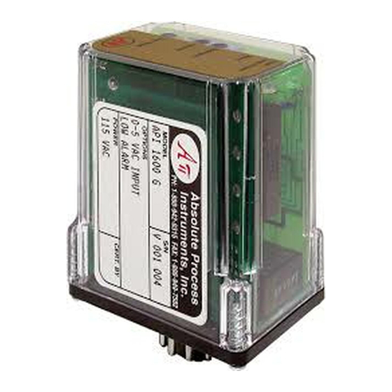
AC Input Alarm Trips, Factory Ranged
Input:
0-50 mVAC to 0-300 VAC, 0-1 mAAC to 0-900 mAAC
Output:
One 8 Amp DPDT Relay or Two 8 Amp SPDT Relays
O Precision Internal AC/DC Converter
O Field Adjustable Setpoints
O Plug-In Design for Fast Installation
O Input LoopTracker
and Alarm Status LEDs
®
O Alarm Test Button
Applications
Q Process Limit Backup Alarm
Q Over, Under, Out-of-Range Voltage or Current Alarm
Q Heater Break, Conveyor Jam Alarm
AC Input Range
Factory configured, please specify AC input range
Voltage:
0-50 mVAC
to
Current:
0-1 mAAC
to
System voltages must not exceed socket voltage rating
Input Impedance (Voltage Input)
220 kΩ minimum
Input Voltage Burden (Current Input)
1.0 V
maximum
RMS
Input Frequency
40 Hz to 1000 Hz sinusoidal
Input Protection, Common Mode
750 VDC or 750 VAC
p
LoopTracker
Variable brightness LED indicates input level and status
API 1600 G Relay Output
Two SPDT form C contact sets operating in unison as one
DPDT contact set
One setpoint, 12 turn potentiometer, 0-100% of span
Factory configured alarm type
Normal acting alarm
Standard: HI alarm
Optional: LO alarm
API 1620 G Relay Output
Two independent SPDT form C contact sets
Two setpoints, two 12 turn potentiometers, 0-100% of span
Normal acting alarms
Standard: HI/LO alarm
Options: LO/LO, HI/HI, LO/HI alarms
Internal jumpers for HI/LO, LO/LO, HI/HI, LO/HI
Relay Contact Rating
8 A @ 240 VAC resistive load or 30 VDC resistive load
See graph on other side for relay load ratings
Caution:
Do not exceed socket voltage rating
Use an RC snubber for inductive loads
Deadband
Alarm trip/reset window are symmetrical about the setpoint
API 1600 G
1.0 to 100% of span, 12 turn potentiometer
API 1620 G
Fixed at 1% of span, standard
API 1620 G A Adjustable deadbands, 1.0 to 100% of span,
1 turn potentiometer for each setpoint
Output Test Button
Toggles relay(s) to opposite state when pressed
Response Time
70 milliseconds typical
Ambient Temperature Range and Stability
–10°C to +60°C operating ambient
Better than ±0.02% of span per °C stability, calculated, not
tested
Housing and Sockets
IP 40, requires installation in panel or enclosure
API 011 or API 011 FS socket
Socket mounts to 35 mm DIN rail or can be surface mounted
Power
Standard:
115 VAC ±10%, 50/60 Hz, 2.5 W max.
P option:
85-265 VAC 50/60 Hz, 60-300 VDC, 2.5 W typ.
A230 option: 230 VAC ±10%, 50/60 Hz, 2.5 W max.
D option:
9-30 VDC, 2.5 W typical
A
A
P
P
BSOLUTE
BSOLUTE
ROCESS
ROCESS
Variable Brightness Input LED
Bi-Color Relay LED
Deadband Adjustment
Setpoint Adjustment
Output Test Button
API 1600 G
0-300 VAC
A Option Deadband Adjustments
0-900 mAAC
Variable Brightness Input LED
Bi-Color Relay 2 LED
Bi-Color Relay 1 LED
Setpoint 2 Adjustment
Setpoint 1 Adjustment
Output Test Button
API 1620 G
Description
The API 1600 G and API 1620 G are factory configured for an
AC voltage or current input and provide alarm contact outputs.
Heavy duty relay contacts allow the module to directly control
high capacity loads.
The API 1600 G provides a single setpoint adjustment and
DPDT relay contacts. The alarm output is normal acting
and can be factory configured for HI or LO operation. Top-
accessible potentiometers are used to adjust the alarm setpoint
and deadband.
The API 1620 G contains two independent setpoints with two
SPDT relay contact outputs. The alarm outputs are normal
acting can be factory or user configured for HI/HI, HI/LO, LO/HI
or LO/LO operation. Top-accessible potentiometers are used to
adjust each alarm setpoint. Deadband is fixed at 1% of span.
Adjustable deadbands are optional.
Model
API 1600 G
API 1600 G A230
API 1600 G P
API 1600 G D
API 1620 G
API 1620 G A230
API 1620 G P
API 1620 G D
Options—add to end of model number
L
1600 G with LO trip. Alarm trips on decreasing signal.
HH 1620 G with HI/HI trip. Alarms trip at their respective
trip points on increasing signal.
LL
1620 G with LO/LO trip. Alarms trip at their respective
trip points on decreasing signal.
LH 1620 G with LO/HI trip instead of HI/LO.
A
1620 G with adjustable deadbands.
U
Conformal coating for moisture resistance
I
I
NSTRUMENTS
NSTRUMENTS
1.75"
1.75"
Input
Standard Alarm Configuration
Factory ranged, specify
Single setpoint one DPDT relay
AC voltage, mV or mA current
range
Factory ranged, specify
AC voltage, mV or mA current
HI/LO alarms, normal acting
range
1220 American Way Libertyville, IL 60048
Phone:
800-942-0315
API 1600 G, API 1620 G
2.38"
2.38"
Quick Link
api-usa.com/1600
LoopTracker and Alarm Status LEDs
API exclusive features include a LoopTracker LED that varies in
intensity with changes in the input signal.
A red/green bi-color alarm status LED (two on the API 1620
G) visually indicate alarm status. These LEDs provide a quick
visual picture of your process at all times.
Output Test
API's exclusive functional test button can be used to verify the
alarm and system operation. Press the Test button to toggle
the alarm relay(s) to the opposite state. The output test but-
ton greatly aids in saving time during initial startup and/or
troubleshooting.
HI alarm, normal acting
85-265 VAC or 60-300 VDC
2 setpoints, 2 SPDT relays
85-265 VAC or 60-300 VDC
Accessories—order as a separate line item
API 011
11-pin socket, DIN rail or surface mount
API 011 FS 11-pin finger safe socket, DIN rail or surface mount
API CLP1
Module hold-down spring for high vibration or
mobile applications
API 011 FS
API 011
300 V Rating
300 V Rating
api-usa.com
Fax: 800-949-7502
2.75"
Hot Swappable
Plug-In Design
H H H H H H
H H H H H
H H H H H H
H H H H H
H H H H H H
H H H H H
H H H H H H
H H H H H
H H H H H H
Made in USA
Free Factory
I/O Setup!
Power
115 VAC
230 VAC
9-30 VDC
115 VAC
230 VAC
9-30 VDC
API CLP1
09-21
©
Advertisement

Subscribe to Our Youtube Channel
Related Manuals for Absolute Process Instruments API 1600 G


Summary of Contents for Absolute Process Instruments API 1600 G
- Page 1 Description LoopTracker and Alarm Status LEDs DPDT contact set The API 1600 G and API 1620 G are factory configured for an API exclusive features include a LoopTracker LED that varies in One setpoint, 12 turn potentiometer, 0-100% of span AC voltage or current input and provide alarm contact outputs.
- Page 2 LED indicates an alarm condition. when panel ATTENTION! Éviter les risques de choc! Fermez le signal NOTE: Although the API 1600 G has a pair of relays, these mounting d’entrée, le signal de sortie et l’alimentation électrique avant relays will energize and de-energize in unison.
Need help?
Do you have a question about the API 1600 G and is the answer not in the manual?
Questions and answers