Table of Contents
Advertisement
Available languages
Available languages
Quick Links
CAN GMT
SEP 40
General Purpose Controller 80c32,
Smart Eprom Programmer 40 pins
80c320, 89c51Rx2
MANUALE UTENTE
USER MANUAL
Via dell' Artigiano, 8/6
®
40016 San Giorgio di Piano
grifo
(Bologna) ITALY
E-mail: grifo@grifo.it
ITALIAN TECHNOLOGY
http://www.grifo.it
Tel. +39 051 892.052 (a. r.) FAX: +39 051 893.661
Edition 3.10
SEP 40
, GPC
http://www.grifo.com
Rel. 09 Spetember 2002
®
®
, grifo
, are trade marks of grifo
®
Advertisement
Table of Contents

Related Manuals for Grifo SEP 40

Summary of Contents for Grifo SEP 40
- Page 1 (Bologna) ITALY E-mail: grifo@grifo.it ITALIAN TECHNOLOGY http://www.grifo.it http://www.grifo.com Tel. +39 051 892.052 (a. r.) FAX: +39 051 893.661 Edition 3.10 Rel. 09 Spetember 2002 SEP 40 ® ® ® , grifo , are trade marks of grifo , GPC...
- Page 3 General Purpose Controller 80c32, Smart Eprom Programmer 40 pins 80c320, 89c51Rx2 SEP 40 è un programmatore compatto, veloce e potente in grado di supportare tutti i tipo di dispositivi programmablili. Tramite il connettore ISP è inoltre in grado di programmare un dispositivo supportato direttamente su scheda.
- Page 4 IMPORTANT ® Although all the information contained herein have been carefully verified, grifo assumes no responsability for errors that might appear in this document, or for damage to things or persons resulting from technical errors, omission and improper use of this manual and of the related software and hardware.
- Page 5 STRUTTURA CONSIGLIATA DEL CONNETTORE ISP ......... 12 INSTALLAZIONE ........................14 CONNESSIONE DI SEP 40 COL PC .................. 14 PROBLEMI DI COLLEGAMENTO SEP 40 E PC ............15 LEDS ............................15 SELFTEST E CALIBRAZIONE ..................16 INSTALLAZIONE DEL PROGRAMMA ................16 CONFIGURAZIONE MINIMA DEL PC ................
-
Page 6: Table Of Contents
TERMINI DELLA GARANZIA ....................47 RISOLUZIONE DEI PROBLEMI ................... 48 ERRORI DI COMUNICAZIONE ..................48 PROLEMI DI LETTURA O PROGRAMMAZIONE ............48 DISPOSITIVI NON SUPPORTATI..................49 ARTICOLI AGGIUNTIVI ......................50 INDICE ANALITICO ........................ 51 Page II SEP 40 Rel. 3.10... - Page 7 ® ITALIAN TECHNOLOGY INDICE DELLE FIGURE 1: F SEP 40 ......................5 IGURA OTO DEL 2: T SEP 40 ................ 8 IGURA EMPI DI PROGRAMMAZIONE DEL 3: C ..................9 IGURA ONTENUTO DELLA CONFEZIONE 4: P ISP ....................12...
- Page 8 THE RECOMMENDED ISP CONNECTOR LAYOUT IN TARGET SYSTEM ..66 INSTALLATION ........................68 CONNECTING SEP 40 TO THE PC .................. 68 PROBLEMS RELATED TO SEP 40 TO PC CONNECTION ......... 69 LEDS ............................69 SELFTEST AND CALIBRATION ..................70 INSTALLING PROGRAMMER SOFTWARE ..............70 MINIMAL PC CONFIGURATION ..................
- Page 9 ITALIAN TECHNOLOGY OTHER ..........................100 WARRANTY TERMS ......................101 TROUBLESHOOTING ......................102 COMMUNICATION ERRORS ..................102 READING OR PROGRAMMING PROBLEMS ............102 UNSUPPORTED TARGET DEVICE ................103 ADDITIONAL TOOLS ......................104 ALPHABETICAL INDEX ...................... 105 SEP 40 Rel. 3.10 Page V...
- Page 10 ® grifo ITALIAN TECHNOLOGY FIGURES INDEX 1: P SEP 40 .................. 59 IGURE HOTO OF PROGRAMMER 2: SEP 40 ..................62 IGURE PROGRAMMING TIMES 3: P ......................63 IGURE ACKAGE CONTENT 4: ISP P ........................66 IGURE INOUT 5: ISP ....................
- Page 11 Per un corretto rapporto coi prodotti, é necessario garantire leggibilità e conservazione del manuale, anche per futuri riferimenti. In caso di deterioramento o più semplicemente per ragioni di approfondimento tecnico ed operativo, consultare i nostri siti www.grifo.it o www.grifo.com o direttamente l’Assistenza Tecnica autorizzata.
- Page 12 INFORMAZIONI PRELIMINARI INFORMAZIONI PRELIMINARI SEP 40 è un programmatore universale ed un tester logico dotato di 48 potenti pindriver nella configurazione base espandibili fino a 256. Questa struttura permette di aggiungere facilmente il supporto a nuovi dispositivi. Il costo è molto competitivo rispetto ai concorrenti della stessa classe, ottenendo il miglior rapporto prezzo/prestazioni, ma l'affidabilità...
- Page 13 Windows 95/98/Me/NT/2000/XP progettato per rispondere alle rigorose esigenze dei tecnici sul campo e dei laboratori di programmazione. SEP 40 supporta tutti i tipi e generi di tecnologia al silicio per dispositivi programmabili. Ha un prezzo molto competitivo ma è un programmatore affidabile grazie al suo eccellente progetto hardware.
- Page 14 ITALIAN TECHNOLOGY SEP 40 è pilotato da un programma di controllo facile da usare, con menù a tendina, tasti di scelta rapida ed aiuto in linea. Si può selezionare un dispositivo target mediante la classe a cui appartiene, dal nome del produttore o semplicemente digitando una parte del nome del rivenditore e/o del dispositivo stesso.
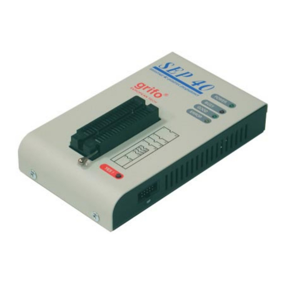
- Page 15 ® ITALIAN TECHNOLOGY 1: F SEP 40 IGURA OTO DEL SEP 40 Rel. 3.10 Pagina 5...
- Page 16 - Connettore di alimentazione - Connettore ISP Nota: Quando SEP 40 non svolge alcuna attività, il programma di controllo lo communta in “modalità sospesa”. In questo stato il consumo è ridotto a meno di un Watt di potenza. Per questo il programmatore non ha alcun interruttore di accensione/spegnimento.
- Page 17 - (*2) gli adattatori disponibili per dispositivi oltre i 40 pin sono pochi. Valutate l'acquisto di un programmatore più potente (UEP 48, JetProg) se avete bisogno di programmare un dispositivo con più di 40 pin IC TESTER - RAM Statiche: 6116.. 624000 SEP 40 Rel. 3.10 Pagina 7...
- Page 18 16 sec AT89C52 Programmazione e verifica 18, 5 sec 16, 5 sec 2: T SEP 40 IGURA EMPI DI PROGRAMMAZIONE DEL OPERAZIONI SUI DISPOSITIVI STANDARD - Selezione intelligente del dispositivo per tipo, produttore o typed frazione del nome - Programmazione ISP - Verifica se è...
- Page 19 ® ITALIAN TECHNOLOGY 3: C IGURA ONTENUTO DELLA CONFEZIONE SEP 40 Rel. 3.10 Pagina 9...
- Page 20 - Binario - HEX: Intel, Intel EXT, Motorola S-record, MOS, Exormax, Tektronix, ASCII-space-HEX CONTENUTO DELLA CONFEZIONE - SEP 40 - Cavo con due connettori tipi D da 25 pin, per collegare il progammatore al PC - Adattatore di rete - POD diagnostico per auto diagnosi del programmatore - Coperchio di metallo per zoccolo ZIF (anti polvere) - Mini-CD con il programma di controllo e altre di utilità...
- Page 21 Se dovete effettuare un'altra operazione sul dispositivo target, tornate al punto 5. NOTA: Se la scheda del dispositivo target utilizza gli stessi segnali della programmazione ISP, è necessario separarli mediante opportuni resistori. SEP 40 Rel. 3.10 Pagina 11...
- Page 22 - Usate solo il cavo ISP in dotazione. Con altri cavi ISP (di diverso materiale, lunghezza, ecc.), la programmazione potrebbe essere non affidabile. - SEP 40 può alimentare il dispositivo target (in maniera limitata anche la scheda su cui è montato), ma il viceversa non è possibile.
- Page 23 IGURA ONNETTORE CONSIGLIATO PER LA SCHEDA TARGET H/L/read driver connector 7: D SEP 40 IGURA RIVER La corrispondenza tra segnali ISP e pin del connettore può variare da dispositivo a dispositivo. Per conoscerla, selezionare il dispositivo desiderato nel programma di controllo (menu Device / Select Device) e premere il pulsante “Additional Info”...
- Page 24 LED si accendono simultaneamente, poi i tre LED di stato si spengono e si riaccendono in sequenza uno dopo l'altro, infine il LED di alimentazione si pone in bassa luminosità, a questo punto il SEP 40 è pronto a ricevere comandi. Accendete anche il PC e fate partire il programma di controllo.
- Page 25 Non va tralascitao il tipo di PC, il produttore, la velocità, il sistema operativo e la versione, programmi residenti e la configurazione della porta parallela. LEDS SEP 40 è fornito di 4 LEDs per visualizzare lo stato dell'alimentazione e lo stato interno del programmatore. Riferitevi alla figura 11 per localizzare i LEDs. COLORE...
- Page 26 Inserite il Mini-CD nel lettore CD, il programma si installerà automaticamente. L'installatore (setup.exe) vi guiderà passo passo attraverso il processo di installazione ed eseguirà le operazioni necessarie precedenti alla prima esecuzione. Eseguite il programma Install dal CD. Pagina 16 SEP 40 Rel. 3.10...
- Page 27 Per ottenere il massimo dalle capacità del programmatore consigliamo di usare la versione più aggiornata di PG4U.EXE o PG4UW.EXE. Potete scaricare l'ultima versione del programma di controllo dai siti internet http://www.grifo.com o http://www.grifo.it. AGGIORNARE IL PROGRAMMA DI CONTROLLO Dopo aver scaricato l'ultima versione del file, semplicemente clickateci sopra. Per il programma DOS è...
- Page 28 - Quando connettete il programmatore al PC: PRIMA inserite il cavo di comunicazione POI il connettore di alimentazione. - Quando scollegate il programmatore dal PC: PRIMA scollegate il connettore di alimentazione POI il cavo di comunicazione. Pagina 18 SEP 40 Rel. 3.10...
- Page 29 ® ITALIAN TECHNOLOGY Pulsante YES! Zoccolo ZIF LEDs Connettore ISP Connettore Porta Parallela Connettore Alimentazione 11: P IGURA IANTA DEGLI ELEMENTI 12: C IGURA AVO PROGRAMMAZIONE IN DOTAZIONE SEP 40 Rel. 3.10 Pagina 19...
- Page 30 Il menu Device contiene i comandi per manipolare il dispositivo da programmare. Il menu File mette a disposizione i comandi di gestion files e directory. Il menu Buffer viene usato per la manipolazione del contenuto del buffer. Pagina 20 SEP 40 Rel. 3.10...
- Page 31 Mentre sotto Windows fate doppio click sull'icona di PG4UW. Dopo la partenza, PG4U/PG4UW scandisce tutte le porte esistenti per trovarci un programmatore grifo ® collegato. PG4U/PG4UW è il programma comune a tutti i programmatori grifo ® per cui cercherà di trovare tutti i tipi.
-
Page 32: Lista Dei Tasti Speciali
QUIT & save Termina il PG4U/PG4UW e salva le impostazioni <Ctrl+F1> Mostra informazioni aggiuntive sul dispositivo target corrente <Ctrl+F2> ERASE Riempie il buffer con un valore assegnato <Ctrl+Shift+F2> Riempie il buffer con un valori casuali Pagina 22 SEP 40 Rel. 3.10... -
Page 33: Comandi Del Programma Di Controllo
Carica un file di progetto, che contiene la configurazione per i dispositivi da usare e la configurazione dell'interfaccia utente. La finestra standard Load project contiene un'altra finestra - Project description - nella parte bassa. Quest'ultima mostra le informazioni contenute nel file selezionato al momento dalla finestra Load project. SEP 40 Rel. 3.10 Pagina 23... - Page 34 2. Viene mostrata la lista dei files usati di recente, clickare sul nome del file desiderato. Nota: Quando un file viene ricaricato, si assume che sia del formato con cui è stato salvato l'ultima volta. Pagina 24 SEP 40 Rel. 3.10...
- Page 35 File / Exit and save Questo comando dealloca lo heap, cancella il buffer su disco (se esiste), salva nel file di configurazione le impostazione relative agli ultimi 10 dispositivi usati e restituisce le risorse al sistema operativo. SEP 40 Rel. 3.10 Pagina 25...
- Page 36 Il dispositivo selezionato viene salvato automaticamente nella lista dei 10 dispositivi di default raggiungibile mediante il comando Device / Select from default devices. Se desiderate visualizzare ulteriori informazioni sul dispositivo corrente, premete ma Pagina 26 SEP 40 Rel. 3.10...
- Page 37 Device / Select EPROM /Flash by ID Si usa questo comando per selezionare automaticamente una EPROM o una Flash leggendo l'ID del dispositivo. Il programmatore può identificare il dispositivo leggendo l'ID del produttore e SEP 40 Rel. 3.10 Pagina 27...
- Page 38 (default disabilitato, cioè DISABLE) verifica dopo la lettura (default disabilitato, cioè DISABLE) verifica dopo la programmazione (una volta: ONCE, due volte: TWICE) opzioni verifica (VCC nominal e 5%, VCC nominal e 10%, VCCmin VCCmax) Pagina 28 SEP 40 Rel. 3.10...
- Page 39 Ignorare o aggiungere i numeri non programmati ha senso solo se almeno un dispositivo del lotto corrente sul modulo multi-zoccolo viene completamente programmato e supera la verifica senza errori. SEP 40 Rel. 3.10 Pagina 29...
- Page 40 Vi è il caso speciali dei numeri decimali codificati in binario, o BCD. Ciò significa che ogni cifra decimale viene memorizzato in una cifra esadecimale, ovvero ogni nibble vale da 0 a 9, non sono ammessi i valori da A ad F in un nibble BCD. Pagina 30 SEP 40 Rel. 3.10...
- Page 41 Le etichette identificano ogni linea del file in ingresso. Vengono usate per idnirizzare individualmente ogni riga del file, per cui ogni etichetta dovrebbe essere univoca. Lo scopo è indirizzare la linea da cui inizia il conteggio dei numeri di serie SEP 40 Rel. 3.10 Pagina 31...
- Page 42 ...“nav6” . ogni numero viene scritto all'indirizzo $A7890 ed è composto da 6 bytes. La linea etichettata con “nav6” ha anche la parte opzionale, che viene scritta nel buffer dall'indirizzo $FFFF6 ed è di 10 bytes, quindi il suo ultimo byte viene scritto all'indirizzo $FFFFF. Pagina 32 SEP 40 Rel. 3.10...
- Page 43 Quando viene selezionato un nuovo dispositivo, tutti i valori delle statistiche vengono azzerati e Count down viene disabilitato (Disabled). Il pulsante Reset nel pannello Statistics azzera i valori delle statistiche. Il pulsante Reload Count down nel pannallo Statistics ricarica il valore iniziale di Count down. SEP 40 Rel. 3.10 Pagina 33...
- Page 44 L'esito dell'operazione viene comunicato da una finestra di avviso. Il comando Device / Device options / Operation options permette di specificare un'altra area di lavoro e di impostare ulteriori elementi della sequenza di operazioni di programmazione. Pagina 34 SEP 40 Rel. 3.10...
- Page 45 Se questa condizione non viene rispettata, il programma prende come indirizzo iniziale il primo pari precedente a quello specificato e come indirizzo finale il primo pari successivo a quello specificato. stampa il contenuto del buffer SEP 40 Rel. 3.10 Pagina 35...
- Page 46 Inserite la stringa da cercare nella casella di testo Text to find e la stringa con cui verrà sostituita nella casella Replace with. In Options potete scegliere se la sostituzione avverrà automaticamente o se volete essere avvertiti prima cha avvenga per poterla annullare. Origin indica dove deve iniziare la ricerca. Pagina 36 SEP 40 Rel. 3.10...
- Page 47 Se questa condizione non viene rispettata, il programma prende come indirizzo iniziale il primo pari precedente a quello specificato e come indirizzo finale il primo pari successivo a quello specificato. SEP 40 Rel. 3.10 Pagina 37...
- Page 48 Insert address: Permette di impostare la dimensione della checksum calcolata che verrà scritta nel buffer all'esecuzione di Calculate & insert. L'indirizzo non si può specificare come un intervallo tipo <From address> fino a <To address> ma come indirizzo di Byte. Pagina 38 SEP 40 Rel. 3.10...
- Page 49 Hex file options Contiene diverse opzioni per controllare il caricamento dei file in formato HEX. La prima opzione abilita la cancellazione (erasing) del buffer (col valore desiderato) che avviene automaticamente prima di caricare il file. SEP 40 Rel. 3.10 Pagina 39...
- Page 50 Don’t save options - Non salvare le opzioni e non chiedere se salvare le opzioni. Auto save options - Salva le opzioni senza chiedere conferma. Prompt for save options - Chiede all'utente se vanno o non vanno salvate le opzioni. Pagina 40 SEP 40 Rel. 3.10...
- Page 51 PC e programmatore (esampio, il programma di controllo indica che il programmatore è assente, la comunicazione col programmatore non è affidablie, ecc.). Se è stata abilitata la comunicazione automatica allora il programma di controllo imposta la massima velocità possibile. SEP 40 Rel. 3.10 Pagina 41...
- Page 52 Viene visualizzata sullo schermo l'avvenuta inserzione di un nuovo dispositivo. La modalità può essere annullata premendo il tasto <Esc> durante l'attesa di inserzione di un nuovo dispositivo. Nota: Durante l'attesa di un nuovo dispositivo il LED BUSY lampeggia. Pagina 42 SEP 40 Rel. 3.10...
- Page 53 Dopo l'accettazione della password avviene il passaggio in modalità protetta, la stessa password serve per tornare in modalità normale. 2. aprendo un progetto precedentemente salvato in modalità protetta. SEP 40 Rel. 3.10 Pagina 43...
- Page 54 è in grado di rimediare in autonomia, quindi deve contattare il produttore. In tal caso è indispensabile allegare al messaggio per il produttore anche il report diagnostico, in quanto questo può aiutare il produttore a localizzare più rapidamente la causa del problema e a risolverlo. Pagina 44 SEP 40 Rel. 3.10...
- Page 55 Informazioni dettagliate sui comandi indivuduali si possono trovare nell'Help in linea. Nota: Le informazioni sono precise al momento della pubblicazione dello stesso. I nostri prodotti sono aggiornati di continuo. Si prega di consultare il sito www.grifo.it o www.grifo.com. Help / Supported devices Mostra una lista con tutti i dispositivi supportati da almeno un programmatore.
-
Page 56: Caratteristiche Software Aggiuntive
Fa apparire una finestra che mosta le informazioni di copyright ed il numero di versione. CARATTERISTICHE SOFTWARE AGGIUNTIVE ® PG4U/PG4UW è il programma di controllo comune a tutti i programmatori grifo . Quindi potreste trovare alcune voci di menu che non si riferiscono al vostro programmatore. -
Page 57: Termini Della Garanzia
La garanzia non copre danni prodotti da usura, lacerazioni o danneggiamenti meccanici. Allo stesso ® modo non copre prodotti manipolati e/o riparati e/o aperti da personale non autorizzato dalla grifo o prodotti che sono stati danneggiati durante un trasporto oppure usati e/o installati e/o maneggiati impropriamente. -
Page 58: Risoluzione Dei Problemi
- Aggiornate il programma di controllo. I produttori di elettronica creano nuovi dispositivi quasi ogni giorno per cui la cosa migliore è cercare il dispositivo che serve nell'ultima versione del PG4U/PG4UW. Se non lo trovate consultate il paragrafo“DISPOSITIVI NON SUPPORTATI”. Pagina 48 SEP 40 Rel. 3.10... -
Page 59: Dispositivi Non Supportati
“Blank check test” tramite il menu Device/Blank Check o premendo il tasto <F6> per accertarvi che il dispositivo sia leggibile ma vuoto. - SEP 40 può effettuare un test di auto diagnostica per verificare il corretto funzionamento dei componenti interni. Selezionate il menu Diagnostic e seguite le istruzioni a schermo. Tenete presente che il selftest deve essere eseguito con lo zoccolo ZIF vuoto, altrimenti sia il programmatore sia il dispositivo che vi si trova potrebbero essere danneggiati. -
Page 60: Articoli Aggiuntivi
® grifo , i convertitori di formato permettono di usare formati diversi dal classico DIL. Per ulteriori informazioni su quale convertitore sia adatto al vostro programmatore si prega di ® contattare la grifo direttamente. CONVERTITORI DI DESCRIZIONE FORMATO DIL20/PLCC20 ZIF Convertitore di formato da DIL 20 a PLCC 20 ZIF. -
Page 61: Indice Analitico
CONNESSIONE 12 CONTENUTO DELLA CONFEZIONE 10 CONVERTITORI DI FORMATO 48 DAC 6 DESCRIZIONE SOFTWARE 19 DISPOSITIVI NON SUPPORTATI 47 DISPOSITIVI SUPPORTATI 7 ECP/EPP 13 ENCRYPTION 23 ERROR LED 13 ESD 6 FILES SUPPORTATI 10 SEP 40 Rel. 3.10 Pagina 51... - Page 62 MODIFICHE 33 MODULI ADATTATORI 49 MOS 21 MOTOROLA 21 PACKAGE ADAPTER 48 PACKAGE SUPPORTATI 7 PASSWORD 41 PINDRIVER 6 POD 14 POF 21 PORTA PARALLELA 2, 13 PORTA STAMPANTE 2, 13 POWER LED 13 Pagina 52 SEP 40 Rel. 3.10...
- Page 63 SELEZIONARE UN DISPOSITIVO 24 SELFTEST 14, 42 SERIALIZZAZIONE 27 STATISTICHE 31 SUPPORTO 47 TARGET 2 TEKTRONIX 21 TEMPI DI PROGRAMMAZIONE 8 ULTERIORI INFORMAZIONI 44 VCCP 6 VERIFICA 32 VPP1 6 VPP2 6 ZIF 2 SEP 40 Rel. 3.10 Pagina 53...
- Page 64 ® grifo ITALIAN TECHNOLOGY Pagina 54 SEP 40 Rel. 3.10...
- Page 65 This document is copyrighted, all rights reserved. This document or any part of it may not be copied, reproduced or translated in any form or in any way without the prior written permission of grifo ®...
- Page 66 PRELIMINARY INFORMATION PRELIMINARY INFORMATION SEP 40 is a small, fast and powerful programmer of all kinds of programmable devices. Using build- in in-circuit serial programming (ISP) connector the programmer is able to program ISP capable chips in-circuit. It has design, which allows to easily add new devices to the device list. Nice “value for money”...
- Page 67 Programmer is built to meet the demands of the development labs and field engineers to universal, but portable programmer. SEP 40 is a small, fast and powerful programmer of all kinds of programmable devices. Using build- in in-circuit serial programming (ISP) connector the programmer is able to program ISP capable chips in-circuit.
- Page 68 Various socket converters are available to handle device in PLCC, SOIC and other packages. Advanced design, including protection circuits, original brand components and careful manufacturing allows us to provide a three-year warranty on parts and labor for the SEP 40 (limited 25,000-cycle warranty on ZIF socket).
- Page 69 ® ITALIAN TECHNOLOGY 1: P SEP 40 IGURE HOTO OF PROGRAMMER SEP 40 Rel. 3.10 Page 59...
- Page 70 ITALIAN TECHNOLOGY TECHNICAL FEATURES TECHNICAL FEATURES SEP 40 ELEMENTS - SEP 40 programmer - Connection cable PC-programmer - ISP cable - Diagnostic POD for selftest - Anti-dust cover for ZIF socket - Wall plug adapter 220V to 15V DC/500mA, unstabilized...
- Page 71 (*2) - there exist only few adapters for devices with more than 40 pins. Therefore think please about more powerfull programmer (UEP 48, JetProg), if you need to program devices with more than 40 pins Look please at list of all supported devices. IC TESTER - Static RAM: 6116.. 624000 SEP 40 Rel. 3.10 Page 61...
- Page 72 Programming and verification 18 sec 16 sec AT89C52 Programming and verification 18.5 sec 16.5 sec 2: SEP 40 IGURE PROGRAMMING TIMES DEVICE OPERATIONS STANDARD - Intelligent device selection by device type, manufacturer or typed fragment of part name - ISP programming...
- Page 73 ® ITALIAN TECHNOLOGY 3: P IGURE ACKAGE CONTENT SEP 40 Rel. 3.10 Page 63...
- Page 74 - External power supply (suitable for respective programmer) - Diagnostic POD for selftest of programmer - Cap for ZIF socket (anti-dust cover) - Mini-CD with the control program, this User’s manual and additional files - Shipping case Page 64 SEP 40 Rel. 3.10...
- Page 75 If you need another action on target device, you continue with step 5. NOTE: If target system use signals needed for ISP programming, it’s necessary separate them from target device by appropriate resistors. SEP 40 Rel. 3.10 Page 65...
- Page 76 - Use only attached ISP cable. When you use other ISP cable (other material, length…), programming may occour unreliable. - SEP 40 can supply target device (target system with limitation), but target system cannot supply SEP 40. - SEP 40 apply programming voltage to target device and checks his value (target system can modify programming voltage).
- Page 77 IGURE ARGET BOARD SUGGESTED CONNECTOR H/L/read driver connector 7: ISP SEP 40 IGURE DRIVER OF Correspondance between ISP signals and connector pins may vary according to the device to be programmed. To know this correspondance, please select the device desired in the control program (menu Device / Select Device) and press “Additional Info”...
- Page 78 At this time all ‘work result’ LEDs (and ‘POWER’ LED) light up successive and then switch off. Once the POWER LED lights with low brightness then the SEP 40 programmer is ready to run. Next switch on the PC and run the control program for SEP 40.
- Page 79 Don’t forget please to tell PC type, manufacturer, speed, operating system type and version, resident programs; your parallel port I/O manufacturer and type. LEDS SEP 40 is provided with 4 LEDs to visualize power supply status and operating programmer status. Please refer to figure 11 to locate the LEDs. COLOUR...
- Page 80 Insert delivered mini-CD to your CD drive and instal program starts automatically. Install program (setup.exe), which will guide you through the installation process and which will do all the necessary steps before you can first run the control program. Run Install program from CD. Page 70 SEP 40 Rel. 3.10...
- Page 81 In order to exploit all the capabilities of programmer we recommend using the latest version of PG4U.EXE or PG4UW.EXE . You may download the latest version of programmer software from Internet site http://www.grifo.com or http://www.grifo.it. UPGRADING THE PROGRAMMER SOFTWARE After downloading the file, just click on it. DOS program needs you to click also the “install.exe”...
- Page 82 - When connecting the programmer to the PC: FIRST insert the communications cable and THEN the power-supply connector. - When disconnecting the programmer from the PC: FIRST disconnect the power-supply connector and THEN the communication cable. Page 72 SEP 40 Rel. 3.10...
- Page 83 ® ITALIAN TECHNOLOGY YES! Button ZIF Socket LEDs ISP Connector Parallel Port Connector Power Supply Connector 11: S IGURE IDE VIEW AND FRONT VIEW 12: ISP IGURE PROGRAMMING CABLE SEP 40 Rel. 3.10 Page 73...
- Page 84 Device/Verify menu or the keyboard shortcut <F8>. The menu Device contains the device manipulation commands. The menu File contains commands for files and directories. The menu Buffer is to be used for buffer manipulation. Page 74 SEP 40 Rel. 3.10...
- Page 85 ® ® connected any grifo programmer. Program PG4U/PG4UW is common for all the grifo programmers, hence program try to find all supported programmers. Notes: When the PG4U/PG4UW program is started, program is checked for its integrity. Than the program display a standard user menu and waits for your instructions.
- Page 86 <Alt+X> QUIT & save Terminates the PG4U and saving settings too <Ctrl+F1> Displays additional information about current device <Ctrl+F2> ERASE Fills the buffer with a given value <Ctrl+Shift+F2> Fills the buffer with random values Page 76 SEP 40 Rel. 3.10...
- Page 87 This option is used for loading project file, which contains device configuration buffer data saved and user interface configuration. The standard dialog Load project contains additional window - Project description - placed at the bottom of dialog. This window is for displaying information about currently selected SEP 40 Rel. 3.10 Page 77...
- Page 88 Lastly used files are listed before files used far off. To Reload a file: 1. From the File menu, choose Reload file. 2. List of lastly used files is displayed. Click the file you want to reload. Page 78 SEP 40 Rel. 3.10...
- Page 89 File / Exit and save The command deallocates heap, cancels buffer on the disk (if exists), saves current setting of last 10 selected devices to disk and returns back to the operation system SEP 40 Rel. 3.10 Page 79...
- Page 90 Selected device is automatically saved to buffer of default devices (max. 10 devices). This buffer is accessible with Device / Select from default devices command. If you wish display additional information about the current device, use an <Ctrl+F1> key. Page 80 SEP 40 Rel. 3.10...
- Page 91 Device / Select EPROM /Flash by ID Use this command for autoselect an EPROM or Flash as active device by reading the device ID. The programmer can automatically identify certain devices by the reading the manufacturer and SEP 40 Rel. 3.10 Page 81...
- Page 92 (default ENABLE) check ID bytes (default ENABLE) - group Command execution: blank check before programming (default DISABLE) erase before programming (default DISABLE) verify after reading (default ENABLE) verify after programming (ONCE, TWICE) Page 82 SEP 40 Rel. 3.10...
- Page 93 Ignoring or writing not programmed serial values is only used when at least one device from current batch of devices in multiple socket module programmer is completely programmed and verified without errors. Device / Device options / Serialization / Incremental mode SEP 40 Rel. 3.10 Page 83...
- Page 94 The special case is Binary Dec, that means BCD number style. BCD means the decimal number is stored in hexadecimal number, i.e. each nibble must have value from 0 to 9. Values A to F are not allowed as nibbles of BCD numbers. Page 84 SEP 40 Rel. 3.10...
- Page 95 Labels are identifiers for each line of input file. They are used for addressing each line of file. The labels should be unique. Addressing lines of file means, the required start label entered by user defines line in input file from which serial values reading starts. SEP 40 Rel. 3.10 Page 85...
- Page 96 $A7890. All values have size 6 bytes. The line with „nav6“ label has also second value definition, which is written to buffer on address $FFFF6 and has size 10 bytes, i.e. the last byte of this value will be written to address $FFFFF. Page 86 SEP 40 Rel. 3.10...
- Page 97 If device operation is finished with error(s) it is not successful operation. When new device type is selected, all statistics values are set to zero and Count down is set to Disabled. Reset button in Statistics panel reset statistics values. SEP 40 Rel. 3.10 Page 87...
- Page 98 This command allows to programming of the all device or its part by the data of the buffer. The control program reports a result of this action by a write of an error message to INFO window. The menu command Device / Device options / Operation options allows to set another working Page 88 SEP 40 Rel. 3.10...
- Page 99 This block must started on even address and must have an even number of bytes. If this conditions do not fulfil, the program modifies addresses itself (start address is moved on lower even address and/or end address is moved on higher odd address). SEP 40 Rel. 3.10 Page 89...
- Page 100 Backward searches toward the beginning. In view mode searches all buffer. Origin specifies where the search should start. Find & Replace dialog box Enter the search string in the Text to find string input box and enter the replacement string in the Page 90 SEP 40 Rel. 3.10...
- Page 101 Buffer / Move block This command is used to move specified block of data in current buffer on new address. Target address needn’t be out from source block addresses. Source address block (or part) will be filled SEP 40 Rel. 3.10 Page 91...
- Page 102 From address: This is a start address of block selected for calculating checksums in buffer. Address is defined as Byte address. To address: This is an end address of block selected for calculating checksums in buffer. Address is defined as Byte address. Page 92 SEP 40 Rel. 3.10...
- Page 103 Load file format allows to set mode of file format recognition for loading files. When automatic file format is selected, program analyses format of loading file and test file for each of supported formats, that are available in program. If file format matches one of supported formats, the file SEP 40 Rel. 3.10 Page 93...
- Page 104 Default start-up directory means directory, from which program is called. Directory in which program was lastly ended means the last current directory when program was lastly ended. This directory assumes Page 94 SEP 40 Rel. 3.10...
- Page 105 Establish communication - allows manual or automatic establishing communication for a new programmer. Speed - sets speed, if a manual establishing communication is selected, which PC sends data into SEP 40 Rel. 3.10 Page 95...
- Page 106 MASTER socket group box allows user to set socket which is preferentially used for device reading operation. Enable/Disable socket checkbox array allows user to set enabling and disabling of each socket individually. Disabled sockets are ignored for any device operation. Page 96 SEP 40 Rel. 3.10...
- Page 107 Protected mode is special mode of program. When program is in Protected mode, there are disabled program operation and commands which can modify buffer or device settings. Protected mode is used for prevent operator from modify buffer or device settings due to insignificance. SEP 40 Rel. 3.10 Page 97...
- Page 108 This command activates a test section for ICs separated by compatibility to any libraries (on distribution diskette). First select an appropriate library, wished device and then a mode for test vectors run (Loop, Single step). Control sequence and test results are displayed to Log window. Page 98 SEP 40 Rel. 3.10...
- Page 109 Detailed information on individual menu commands can be found in the integrated on-line Help. Note: Information provided in this manual is intended to be accurate at the moment of release, but we continuously improve all our products. Please consult www.grifo.com or www.grifo.it. Help / Supported devices This command displays list of all devices supported by at least one type of all supported programmers.
- Page 110 SOFTWARE ADDITIONAL FEATURES ® PG4U/PG4UW is common control program for all of the grifo programmers. Thus, during work with him its possible to find some items, those refer not to current selected programmer. There is possible to attach to selected file “device associated file” too. This file may be automatically loaded into the buffer, if item Device options/Associated file/Automatic load is set to Yes.
- Page 111 ® Before sending the programmer, please contact grifo directly to agree about the shipping modalities. However it is essential to return to grifo ® the transport packing of the programmer in good state, the cable, the power supply and include a brief and exhaustive descrtiption of the problem encountered.
- Page 112 Your target device please refer to paragraph “UNSUPPORTED TARGET DEVICE”. - If the target device has never been programmed before or has been deleted it has returned to blank state. Perform “Blank check test” through Device/Blank Check menu or the keyboard shortcut Page 102 SEP 40 Rel. 3.10...
- Page 113 ITALIAN TECHNOLOGY <F6>. - SEP 40 can perform a self test to assure the correct working of its internal components. Select menu Diagnostics and follow the on screen instuctions. Please remark that self test must be performed with ZIF socket empty, otherwise both the programmer and the device inserted will be damaged, and that self test plus must be performed with the specific diagnostic POD inserted in the ZIF socket.
- Page 114 ITALIAN TECHNOLOGY ADDITIONAL TOOLS ADDITIONAL TOOLS ® To extend easily the already large amount of devices programmable thorugh the grifo programmers, the package converters allow to use also packaging types different from the classic DIL. For more ® information about which converter can be used with your programmer please contact grifo directly.
- Page 115 BUFFER 35 DIAGNOSTICS 44 FILE 23 HELP 45 OPTIONS 39 DEVICE 2 DEVICE OPTIONS 28 DEVICE SELECTION 26 DIAGNOSTICS 44 ELEMENTS 6 ENCRYPTION 25 ERASE 35 ERROR 15 FILE FORMATS 10, 23 GOOD 15 SEP 40 Rel. 3.10 Page 105...
- Page 116 PACKAGE CONVERTER LIST 50 PARALLEL PORT 2, 15 PASSWORD 43 PC CONFIGURATION 16 PINDRIVERS 6, 7 POD 44 POWER 15 PRINTER PORT 2, 15 PROGRAM 34 PROJECT 23 PROJECT OPTIONS 25 PROTECTED MODE 43 QUICK INSTRUCTIONS 20 Page 106 SEP 40 Rel. 3.10...
- Page 117 REPORT 45 SELFTEST 16, 44 SERIALIZATION 29 SOFTWARE 16 SOFTWARE ADDITIONAL FEATURES 46 SOFTWARE DESCRIPTION 21 SPEED 8 SRAM 7 STATISTICS 33 TEKTRONIX 10 TERMINOLOGY 2 TROUBLESHOOTING 48 VERIFY 34 WARRANTY 47 ZIF 2 SEP 40 Rel. 3.10 Page 107...
- Page 118 ® grifo ITALIAN TECHNOLOGY Page 108 SEP 40 Rel. 3.10...
Need help?
Do you have a question about the SEP 40 and is the answer not in the manual?
Questions and answers