Table of Contents
Advertisement
Available languages
Available languages
Quick Links
MP AVR-51
Microprocessor Programmer
for AVR and family 51
MANUALE UTENTE
USER MANUAL
Via dell' Artigiano, 8/6
40016 San Giorgio di Piano
®
grifo
(Bologna) ITALY
E-mail: grifo@grifo.it
ITALIAN TECHNOLOGY
http://www.grifo.it
Tel. +39 051 892.052 (a.r.) FAX: +39 051 893.661
MP AVR-51
Edition 3.10
, GPC
http://www.grifo.com
Rel 03 January 2001
®
, grifo
®
, are trade marks of grifo
®
Advertisement
Table of Contents

Related Manuals for Grifo MP AVR-51

Summary of Contents for Grifo MP AVR-51
- Page 1 ® grifo (Bologna) ITALY E-mail: grifo@grifo.it ITALIAN TECHNOLOGY http://www.grifo.it http://www.grifo.com Tel. +39 051 892.052 (a.r.) FAX: +39 051 893.661 MP AVR-51 Edition 3.10 Rel 03 January 2001 ® , grifo ® , are trade marks of grifo ® , GPC...
- Page 3 EEPROM seriali dotate di interfaccia tipo IIC (24Cxx), Microwire (93Cxx) ed SPI (25Cxx). MP AVR-51 is a little and portable programmer for MCS51 series and Atmel AVR microcontrollers. MP AVR-51 enables also programming serial EEPROM with interface types IIC (24Cxx), Microwire (93Cxx) and SPI (25Cxx).
- Page 4 IMPORTANT ® Although all the information contained herein have been carefully verified, grifo assumes no responsability for errors that might appear in this document, or for damage to things or persons resulting from technical errors, omission and improper use of this manual and of the related software and hardware.
-
Page 5: Table Of Contents
FORMATI DI FILE SUPPORTATI ..................6 GENERALI ..........................6 INSTALLAZIONE ........................8 CONNESSIONE DI MP AVR-51 COL PC................8 PROBLEMI DI COLLEGAMENTO MP AVR-51 E PC ............. 8 LEDS ............................9 JUMPER ..........................9 INSTALLAZIONE DEL PROGRAMMA DI CONTROLLO ..........9 CONFIGURAZIONE MINIMA DEL PC ................ - Page 6 RISOLUZIONE DEI PROBLEMI ................... 28 ERRORI DI COMUNICAZIONE ..................28 PROLEMI DI LETTURA O PROGRAMMAZIONE ............28 DISPOSITIVI NON SUPPORTATI..................29 DISPOSITIVI ADDIZIONALI ....................30 CONVERTITORI DI FORMATO ..................31 INDICE ANALITICO ........................ 32 Pagina II MP AVR-51 Rel. 3.10...
- Page 7 3: D ......................9 IGURA ESCRIZIONE 4: C ............. 11 IGURA ONNETTORI DI ALIMENTAZIONE E PORTA PARALLELA 5: P ..................11 IGURA OSIZIONE S E TEXTOOL 6: T ................31 IGURA ABELLA CONVERTITORI DI FORMATO MP AVR-51 Rel. 3.10 Pagina III...
- Page 8 SUPPORTED FILE FORMATS ..................40 GENERAL ..........................40 INSTALLATION ........................42 CONNECTING MP AVR-51 TO THE PC ................42 PROBLEMS RELATED TO MP AVR-51 TO PC CONNECTION ......... 42 LEDS ............................43 JUMPER ..........................43 INSTALLING PROGRAMMER SOFTWARE ..............43 MINIMAL PC CONFIGURATION ..................
- Page 9 WARRANTY TERMS ....................... 61 TROUBLESHOOTING ......................62 COMMUNICATION ERRORS ................... 62 READING OR PROGRAMMING PROBLEMS .............. 62 UNSUPPORTED TARGET DEVICE ................. 63 ADDITIONAL TOOLS ......................64 PACKAGE CONVERTERS ....................65 ALPHABETICAL INDEX ......................66 MP AVR-51 Rel. 3.10 Pagina V...
- Page 10 3: LED ..................... 43 IGURE S DESCRIPTION TABLE 4: LPT ..............45 IGURE PORT AND POWER SUPPLY CONNECTOR 5: LED ..................45 IGURE S AND TEXTOOL LOCATION 6: P ..................65 IGURE ACKAGE CONVERTERS TABLE Pagina VI MP AVR-51 Rel. 3.10...
-
Page 11: Introduzione
Per un corretto rapporto coi prodotti, é necessario garantire leggibilità e conservazione del manuale, anche per futuri riferimenti. In caso di deterioramento o più semplicemente per ragioni di approfondimento tecnico ed operativo, consultare i nostri siti www.grifo.it o www.grifo.com o direttamente l’Assistenza Tecnica autorizzata. -
Page 12: Informazioni Generali
Vi sono due versione del programma di controllo: PG4U per DOS e PG4UW per Windows 95/98/NT/2000. Il programma di controllo è comune per tutti i programmatori (UEP 48, EP 32, MP AVR-51, MP PIK e SEEP). CONVENZIONI E TERMINOLOGIA... -
Page 13: Caratteristiche Generali
Centronics dei PC, supportando anche il protocollo bidirezionale. MP AVR-51 viene pilotato da un programma di controllo facile da usare, con menu a tendina, help in linea e abbreviazioni dei comandi. Potete scegliere il dispositivo da programmare in base al tipo, il costruttore o semplicemente da una frazione del part number. -
Page 14: Caratteristiche Tecniche
- Cavo di connessione col PC lungo 1.3 m (4.3 ft.) - Alimentatore 220VAC/12VDC 500 mA non stabilizzato (15VDC se l'assorbimento è 200mA) - Floppy disk 3.5" con il manuale utente in formato .pdf - Floppy disk 3.5" con il software di controllo MP AVR-51 Rel. 3.10 Pagina 4... - Page 15 ® ITALIAN TECHNOLOGY 1: C IGURA ONTENUTO DELLA CONFEZIONE MP AVR-51 Rel. 3.10 Pagina 5...
-
Page 16: Formati Di File Supportati
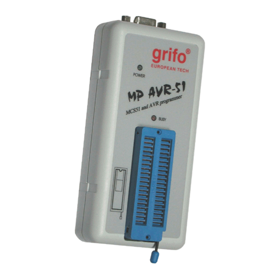
- Tensione di funzionamento 15÷20V DC/200 mA (alimentatore compreso) - Consumo di energia max. 3W - Dimensioni 132x66x30 [mm] (5.2x2.6x1.2 [inch]) - Peso (senza adattatori) 200 g - Temperatura di funzionamento 5÷40 deg C - Umidità 20%.80%, senza condensa MP AVR-51 Rel. 3.10 Pagina 6... - Page 17 ® ITALIAN TECHNOLOGY 2: F IGURA MP AVR-51 Rel. 3.10 Pagina 7...
-
Page 18: Installazione
Collegate l'alimentatore fornito in dotazione alla presa di alimentazione di rete e collegate il connettore mini DIN alla presa di alimentazione etichettata “12 VAC” dell'MP AVR-51. Il LED di alimentazione si accende, a questo punto l'MP AVR-51 è pronto a ricevere comandi. Accendete anche il PC e fate partire il programma di controllo. -
Page 19: Leds
® ITALIAN TECHNOLOGY LEDS L'MP AVR-51 è fornito di 2 LEDs per visualizzare lo stato dell'alimentazione e lo stato interno del programmatore. Riferitevi aella figura 5 per localizzare i LEDs. COLORE DESCRIZIONE Se acceso, indica che il programmatore è... -
Page 20: Configurazione Consigliata Del Pc
I programmi PG4U.EXE (per DOS) e PG4UW.EXE (per Windows) sono usati per pilotare tutti i ® programmatori di marca grifo . Si garantisce il funzionamento sotto i sistemi operativi sopra menzionati senza problemi. Anche il funzionamento in background sotto Windows è privo di errori. - Page 21 ® ITALIAN TECHNOLOGY 4: C IGURA ONNETTORI DI ALIMENTAZIONE E PORTA PARALLELA 1 - Power LED 2 - Busy LED 3 - Textool 5: P IGURA OSIZIONE S E TEXTOOL MP AVR-51 Rel. 3.10 Pagina 11...
-
Page 22: Avvio Rapido
Anche se può essere scomodo dover ogni volta staccare il cavo della stampante e ricollegare quello dell'MP AVR-51, non è possibile collegare il programmatore tramite un data switch, sia meccanico che elettronico. Potete comunque installare una scheda supplementare di I/O per dedicare una porta, esempio LPT2, all'MP AVR-51, mentre la stampante può... -
Page 23: Installazione Del Programma Di Controllo
Il menu Device contiene i comandi per manipolare il dispositivo da programmare. Il menu File mette a disposizione i comandi di gestion files e directory. Il menu Buffer viene usato per la manipolazione del contenuto del buffer. MP AVR-51 Rel. 3.10 Pagina 13... -
Page 24: Descrizione Software
NUOVE VERSIONI DEL PROGRAMMA DI CONTROLLO Per ottenere il massimo dalle capacità del programmatore consigliamo di usare la versione più aggiornata di PG4U.EXE o PG4UW.EXE. Potete scaricare l'ultima versione del programma di controllo dai nostri siti internet http://www.grifo.it o http://www.grifo.com. MP AVR-51 Rel. 3.10... -
Page 25: Aggiornare Il Programma Di Controllo
Dopo la partenza, PG4U/PG4UW scandisce tutte le porte esistenti per trovarci un programmatore collegato. PG4U/PG4UW è il programma comune a tutti i programmatori per cui cercherà di trovare tutti i tipi di programmatori (UEP 48, EP 32, MP AVR-51, MP PIK e SEEP). NOTE... -
Page 26: Descrizione Della Schermata Principale
QUIT & save Termina il PG4U/PG4UW e salva le impostazioni <Ctrl+F1> Mostra informazioni aggiuntive sul dispositivo target corrente <Ctrl+F2> ERASE Riempie il buffer con un valore assegnato <Ctrl+Shift+F2> Riempie il buffer con un valori casuali MP AVR-51 Rel. 3.10 Pagina 16... -
Page 27: Comandi Del Programma Di Controllo
<Ctrl+F1>. Questa azione fornisce la dimensione del dispositivo, la sua organizzazione, l'algoritmo di programmazione e una lista dei programmatori che lo supportano completa con gli eventuali moduli richiesti. MP AVR-51 Rel. 3.10 Pagina 17... - Page 28 Device/options permette di impostare una diversa area di lavoro standard. Impostare l'opzione “Verify data after reading” (verifica dei dati dopo la lettura) in questo menu significa avere maggiore affidabilità nel processo di lettura dati. MP AVR-51 Rel. 3.10 Pagina 18...
- Page 29 Device List Questo comando genera una lista di tutti i dispositivi supportati dal programmatore selezionato e la salva nel file PROGLIST.DEV nella cartella corrente del disco. MP AVR-51 Rel. 3.10 Pagina 19...
-
Page 30: Sottomenu Device Options
Abilitate o disabilitate il caricamento mediante il menu Device/Automatic load. Nome file ed abilitazione vengono salvati sul file PG4U.SET mediante il menu Quit/Yes & save. Special <Alt+S> Operazioni specifiche che dipendono dal dispositivo selezionato. MP AVR-51 Rel. 3.10 Pagina 20... -
Page 31: Menu File
Questo indirizzo non deve per forza trovarsi fuori dal blocco specificato. Il blocco di partenza viene riempito (o solo in parte) con il carattere di blank. Vedere anche “Copy block”. MP AVR-51 Rel. 3.10 Pagina 21... -
Page 32: Menu Opzioni
(monocromatico o a colori). Il cambiamento è immediatamente visibile. Non usate questo comando con schede HERCULES, la scheda viene identificata immediatamente. Questa impostazione viene salvata nel file PG4U.CFG dal comando Options/Save options. Il default è a colori. MP AVR-51 Rel. 3.10 Pagina 22... - Page 33 Attenzione: dato che l'indirizzo viene sottratto dall'inidirizzo di caricamento il risultato può essere un numero negativo. Si prega di impostare tale valore con prudenza. Questa impostazione viene salvata nel file PG4U.CFG dal comando Options/Save options. Come default è disattivato. MP AVR-51 Rel. 3.10 Pagina 23...
- Page 34 Questo comando permette di ripristinare le impostazioni salvate nel file PG4U.CFG con il comando Options/Save options. Potete scegliere da dove verrà letto il file di configurazione (cartella corrente, cartella radice di C: o cartella da cui è stato lanciato PG4U.EXE). MP AVR-51 Rel. 3.10 Pagina 24...
-
Page 35: Menu Quit
Poichè il sistema di help viene continuamete aggiornato con il programma di controllo, può contenere informazioni non incluse in questo manuale. Informazioni dettagliate sui comandi individuali dei menu si possono trovare nell'help in linea integrato. MP AVR-51 Rel. 3.10 Pagina 25... - Page 36 - PG4U non identifica VGA monocromatiche e monitor LCD (quelli usati nei laptops) e quindi può impostare erroneamente i colori. In tal caso selezionate l'opzione Options/Monitor/mono (o LCD). Aggiornamenti a questo manuale si dovrebbero trovare nel file README_P.TXT. MP AVR-51 Rel. 3.10 Pagina 26...
-
Page 37: Termini Della Garanzia
La garanzia copre il programmatore e tutte le sue parti, purchè esenti da difetti di fabbricazione, i materiali e la mano d'opera fino ad un anno (per MP AVR-51, MP PIK e SEEP) o tre anni (UEP 48, EP 32) dalla data di acquisto. La garanzia è altresì limitata a 25000 cicli per lo zoccolo ZIF o 10000 per zoccoli PLCC ZIF. -
Page 38: Risoluzione Dei Problemi
- Se il dispositivo è vergine o è stato usato e poi cancellato si ritrova privo di contenuto. Effettuate un “Blank check test” tramite il menu Device/Blank Check o premendo il tasto <F6> per accertarvi che il dispositivo sia leggibile ma vuoto. MP AVR-51 Rel. 3.10 Pagina 28... -
Page 39: Dispositivi Non Supportati
(sezione programmatori, scegliete il nome del vostro programmatore). Il dispositivo che vi interessa può essere già incluso nel database dell'ultima versione. - Contattate la grifo ® direttamente. Potremmo avere bisogno dei data sheets del componente e, possibilmente, avere dei campioni. -
Page 40: Dispositivi Addizionali
ITALIAN TECHNOLOGY DISPOSITIVI ADDIZIONALI DISPOSITIVI ADDIZIONALI I programmatori della grifo ® possono essere integrati con vari altri prodotti per estendere il campo delle applicazioni e formare un insieme di strumenti adatti all'uso professionale ovunque sia necessario cancellare, programmare o simulare qualunque tipo di EPROM tra le più diffuse ed i microcontrollori più... -
Page 41: Convertitori Di Formato
® grifo , i convertitori di formato permettono di usare formati diversi dal classico DIL. Per ulteriori informazioni su quale convertitore sia adatto al vostro programmatore si prega di ® contattare la grifo direttamente. CONVERTITORI DI DESCRIZIONE FORMATO DIL20/PLCC20 ZIF Convertitore di formato da DIL 20 a PLCC 20 ZIF. -
Page 42: Indice Analitico
MENU FILE 21 MENU OPZIONI 22 MENU QUIT 25 SOTTOMENU DEVICE OPTIONS 20 CONFIGURAZIONE CONSIGLIATA DEL PC 10 CONNESSIONE DI MP AVR-51 COL PC 8 CONSUMO DI ENERGIA 6 CONTENUTO DELLA CONFEZIONE 4 CONVENZIONI 2 CONVERTITORI DI FORMATO 31 DESCRIZIONE DELLA SCHERMATA PRINCIPALE 16... - Page 43 OPERAZIONI SU DISPOSITIVI 4 OPERAZIONI SUL BUFFER 4 PESO 6 PG4U.EXE 10, 13, 14 PG4UW.EXE 10, 13, 14 PORTA PARALLELA 8, 12, 28 PROBLEMI DI COLLEGAMENTO MP AVR-51 E PC 8 PROLEMI DI LETTURA O PROGRAMMAZIONE 28 MP AVR-51 Rel. 3.10 Pagina 33...
- Page 44 ® grifo ITALIAN TECHNOLOGY RISOLUZIONE DEI PROBLEMI 28 TEMPERATURA DI FUNZIONAMENTO 6 TENSIONE DI FUNZIONAMENTO 6 TERMINI DELLA GARANZIA 27 TERMINOLOGIA 2 UMIDITÀ 6 UTILIZZO DEL SOFTWARE 15 ZOCCOLO ZIF 2 MP AVR-51 Rel. 3.10 Pagina 34...
- Page 45 This document is copyrighted, all rights reserved. This document or any part of it may not be copied, reproduced or translated in any form or in any way without the prior written permission of grifo ®...
- Page 46 There are two versions of the control software: PG4U for DOS and PG4UW for Windows 95/98/NT/2000. Control program PG4U/PG4UW is common for all the programmers (UEP 48, EP 32, MP AVR-51, MP PIK and SEEP). CONVENTIONS AND TERMINOLOGY...
- Page 47 The quality of programmer is completed by comfortable control program. MP AVR-51 interfaces with the IBM PC, AT to Pentium Pro, portable or desktop personal computers. A programmer allows you to directly connect to your PC through any standard parallel (printer) port - no special interface card is needed.
- Page 48 - Print PACKAGE INCLUDED - MP AVR-51 programmer - 1.3m (4.3 ft.) connecting cable MP AVR-51 to (IBM) PC - Wall plug adapter 12V DC/ 500mA, unstabilized (output 15V if load 200mA) - Diskette with control program - 3.5" floppy disk with user manual in .pdf format...
- Page 49 ® ITALIAN TECHNOLOGY 1: P IGURE ACKAGE INCLUDED MP AVR-51 Rel. 3.10 Page 39...
- Page 50 GENERAL - Operating voltage 15÷20V DC/200mA - Power consumption 3W max. - Dimensions 132x66x30 [mm] (5.2x2.6x1.2 [inch]) - Weight (without external adapter) ca. 200g - Temperature 5° ÷ 40°C - Humidity 20%..80%, non condensing MP AVR-51 Rel. 3.10 Page 40...
- Page 51 ® ITALIAN TECHNOLOGY 2: P IGURE HOTO MP AVR-51 Rel. 3.10 Page 41...
- Page 52 Please refer ro figure 4. Switch off PC and programmer. Insert the communication cable included with Your MP AVR-51 programmer package to a free printer port on your PC. If Your computer is equipped with only one printer port, substitute the programmer cable for the printer cable Connect the opposite cable end to the programmer.
- Page 53 ® ITALIAN TECHNOLOGY LEDS MP AVR-51 is provided with 2 LEDs to visualize power supply status. Please refer to figure 5 to locate the LEDs. COLOUR DESCRIPTION When on, indicates that the programmer is Power LED Green supplied and working.
- Page 54 - If you want the control program to run in the background, it is necessary to set: (WIN95/98) RIGHT mouse button on the DOS icon/ PROPERTIES/ OTHERS/ BACKGROUND/ Enable; (WIN3xx) in the appropriate PIF file, set the option to Background. MP AVR-51 Rel. 3.10 Page 44...
- Page 55 ® ITALIAN TECHNOLOGY 4: LPT IGURE PORT AND POWER SUPPLY CONNECTOR 1 - Power LED 2 - Busy LED 3 - Textool 5: LED IGURE S AND TEXTOOL LOCATION MP AVR-51 Rel. 3.10 Page 45...
- Page 56 - When disconnecting the programmer from the PC: FIRST disconnect the power-supply connector and THEN the communication cable. From programmer’s point of view the connecting and disconnecting sequence is irrelevant. Protection circuits on all programmer inputs keep it safe. But think of your PC, please. MP AVR-51 Rel. 3.10 Page 46...
- Page 57 Device/Verify menu or the keyboard shortcut <F8>. The menu Device contains the device manipulation commands. The menu File contains commands for files and directories. The menu Buffer is to be used for buffer manipulation. MP AVR-51 Rel. 3.10 Page 47...
- Page 58 In order to exploit all the capabilities of programmer we recommend using the latest version of PG4U.EXE or PG4UW.EXE . You may download the latest version of programmer software (file PG4UARC.EXE or PG4UWARC.EXE) from our Internet sites http://www.grifo.com or http://www.grifo.it.
- Page 59 After start, control program PG4U or PG4UW automatically scans all existing ports and searchs for a programmer there connected. Program PG4U/PG4UW is common for all programmers, hence program tries to find all supported programmers (UEP 48, EP 32, MP AVR-51, MP PIK and SEEP).
- Page 60 <Alt+X> QUIT & save Terminates the PG4U and saving settings too <Ctrl+F1> Displays additional information about current device <Ctrl+F2> ERASE Fills the buffer with a given value <Ctrl+Shift+F2> Fills the buffer with random values MP AVR-51 Rel. 3.10 Page 50...
- Page 61 <Ctrl+F1> key. This command provides a size of device, organization, programming algorithm and a list of programmers (including auxiliary modules), which support this device. You can find here also package information and other general information about current device. MP AVR-51 Rel. 3.10 Page 51...
- Page 62 INFO window. The menu command Device\Options allows to set another working area as the standard. Setting an option Verify data after reading in this menu command means a higher reliability for device reading. MP AVR-51 Rel. 3.10 Page 52...
- Page 63 You can find here a package information and other general information about current device too. Device List This command makes a list of all devices supported by current programmer and saves its to PROGLIST.DEV text file in the current directory on the disk. MP AVR-51 Rel. 3.10 Page 53...
- Page 64 DEVICE\AUTOMATIC LOAD command. You can save both settings i.e. associated file and enabling of automatic load of this file to PG4U.SET file by command QUIT\YES & SAVE. Special <Alt+S> Specific operations that may vary depending on the component selected. MP AVR-51 Rel. 3.10 Page 54...
- Page 65 If this conditions do not fulfil, the program modifies addresses itself (start address is moved on lower even address and/or end address is moved on higher odd address). MP AVR-51 Rel. 3.10 Page 55...
- Page 66 (monochrome or color). The colors change is visible immediately. Don’t use the command for HERCULES card. This card is identified automatically. This setting is saved to file PG4U.CFG by command Options\Save options. Default set is color. MP AVR-51 Rel. 3.10 Page 56...
- Page 67 Please take care of correct setting of this value. This setting is saved to file PG4U.CFG by command Options \ Save options. Default setting means inactive status. MP AVR-51 Rel. 3.10 Page 57...
- Page 68 (*, ?) at least and must be applied correctly by syntax. This setting is saved to CFG file by command Options\Save. Find programmer This item contains commands that are used for setting communication parameters and for selecting new type of programmer. MP AVR-51 Rel. 3.10 Page 58...
- Page 69 - Words describing the keys referred to by the current Help - All other significant words - Current cross-references; press <ENTER> to obtain further information. - Inactive cross-references; use the cursor keys to select one of them and acknowledge with <ENTER> MP AVR-51 Rel. 3.10 Page 59...
- Page 70 Detailed information can be found in the on-line Help. ABOUT MENU When You choose the Info command from the menu, a window appears, showing copyright and version information. MP AVR-51 Rel. 3.10 Page 60...
- Page 71 Warranty guarantees on failure-free operating of the programmer and all its parts, materials and workmanship for one-year (MP AVR-51, MP PIK and SEEP) or three-years (UEP 48, EP 32) from the date of purchase. This warranty is limited to 25,000-cycles on DIL-ZIF socket or 10,000-cycles on PLCC-ZIF sockets).
- Page 72 Your target device please refer to paragraph “UNSUPPORTED TARGET DEVICE”. - If the target device has never been programmed before or has been deleted it has returned to blank state. Perform “Blank check test” through Device/Blank Check menu or the keyboard shortcut <F6>. MP AVR-51 Rel. 3.10 Page 62...
- Page 73 If yes, download the file PG4UARC.EXE (for DOS) or PG4UWARC.EXE (for WIN) and install the new version of the control program. - Contact grifo ® directly. We may need detailed data sheets of your target device and, if possible, samples.
- Page 74 ER 05 Eprom Eraser 05 Erases all UV erasable EPROMs; holds up to 5 EPROMs; programmable timer with three different exposure durations; saves UV lamp lifetime; provided with power supply. MP AVR-51 Rel. 3.10 Page 64...
- Page 75 ITALIAN TECHNOLOGY PACKAGE CONVERTERS ® To extend easily the already large amount of devices programmable thorugh the grifo programmers, the package converters allow to use also packaging types different from the classic DIL. For more information about which converter can be matched with Your programmer please contact ®...
- Page 76 ALPHABETICAL INDEX ALPHABETICAL INDEX AVR FAMILY 43 BINARY 40 BUFFER OPERATIONS 38 COMMUNICATION ERRORS 62 CONNECTING MP AVR-51 TO THE PC 42 CONTROL PROGRAM COMMANDS 51 ABOUT MENU 60 BUFFER MENU 55 DEVICE MENU 51 DEVICE OPTIONS SUBMENU 54 FILE MENU 55...
- Page 77 ® ITALIAN TECHNOLOGY LED 43 MCS51 FAMILY 43 MICROCONTROLLERS 38 MP AVR-51 SPECIFICATION 38 OPERATING VOLTAGE 40 PACKAGE INCLUDED 38 PC CONFIGURATION 43 POWER CONSUMPTION 40 READING OR PROGRAMMING PROBLEMS 62 SERIAL E(E)PROM 38 SOFTWARE DESCRIPTION 48 SOFTWARE INSTALLATION 44...
- Page 78 ® grifo ITALIAN TECHNOLOGY ZIF 38 ZIF SOCKET 36 MP AVR-51 Rel. 3.10 Page 68...
Need help?
Do you have a question about the MP AVR-51 and is the answer not in the manual?
Questions and answers