Table of Contents
Advertisement
Quick Links
Advertisement
Table of Contents
Troubleshooting

Related Manuals for Dinamap PRO 1000V3


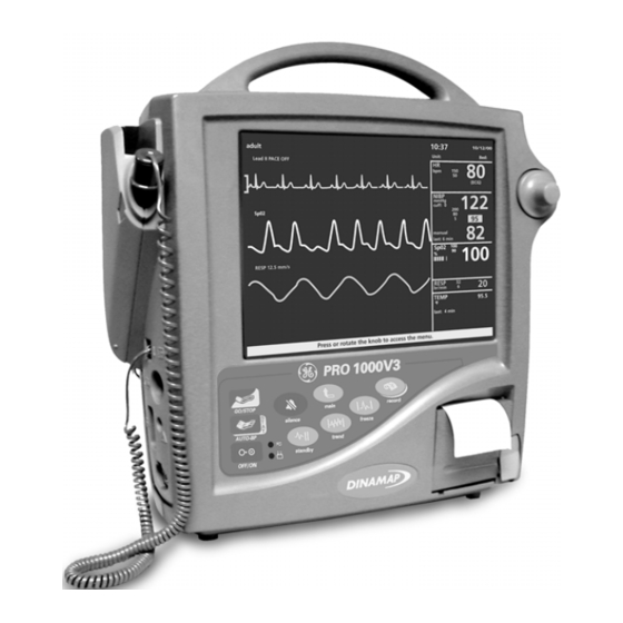
Summary of Contents for Dinamap PRO 1000V3
- Page 1 PRO 1000V3 Monitor Service Manual...
- Page 2 DINAMAP PRO 1000V3 Monitor Service Manual...
- Page 4 The content of this document, including all figures and drawings, is proprietary information of General Electric Medical Systems Information Technologies, provided solely for purposes of operation, maintenance or repair of PRO 1000V3 Monitors. Dissemination for other purposes or copying thereof without the prior written consent of General Electric...
-
Page 6: Table Of Contents
TABLE OF CONTENTS SECTION 1 INTRODUCTION 1.1. Scope of Manual..................1-3 1.2. Manual Changes ..................1-4 Service Policy .................... 1-4 1.3.1 Extended Warranties ................. 1-4 1.3.2 Assistance ....................1-4 1.3.3 Service ......................1-5 1.3.4 Service Loaners and Rentals..............1-6 1.3.5 Repair .......................1-7 1.3.6 Replacement Accessories ................. - Page 7 SECTION 4. GENERAL MAINTENANCE 4.1. Introduction....................4-3 4.2. Setting up the PRO 1000V3 Monitor for the First Time ......4-3 4.2.1 Unpacking and Preparation for Installation..........4-3 4.2.2 Set the Date and the Clock................ 4-5 4.2.3 Parameter Level Functional Testing ............4-6 4.3.
- Page 8 4.7.2 NIBP Tests ..................... 4-20 4.7.2.1 Leak Test.................... 4-21 4.7.2.2 NIBP Calibration Check ..............4-23 4.7.2.3 Pressure Recalibration ............... 4-24 4.7.2.4 Overpressure Test................4-26 4.7.3 ECG Tests ....................4-27 4.7.4 RESP Tests .................... 4-29 4.7.5 TEMP Tests.................... 4-29 4.7.6 Recorder Tests ..................4-30 4.7.7 Battery Tests ..................
-
Page 10: Section 1 Introduction
SECTION 1. INTRODUCTION... - Page 11 ® DINAMAP PRO 1000V3 Service Manual INTRODUCTION...
-
Page 12: Scope Of Manual
® DINAMAP PRO 1000V3 Service Manual SECTION 1. INTRODUCTION 1.1 SCOPE OF MANUAL This Service Manual provides service and parts repair ® information about the DINAMAP PRO 1000V3 Monitor. This manual is intended for use by trained service technicians who are familiar with electromechanical devices and digital and analog circuit techniques. -
Page 13: Manual Changes
® DINAMAP PRO 1000V3 Service Manual is provided to facilitate isolating faults to the subassembly level. 1.2 MANUAL CHANGES If, in the normal use of this manual, you notice errors, omissions, incorrect data, or if you can suggest comments that may help improve this manual, please notify:... -
Page 14: Service
® DINAMAP PRO 1000V3 Service Manual • the product name and model number • a complete description of the problem • the software revision If repair parts or service are necessary, provide the following information: • the product serial number •... -
Page 15: Service Loaners And Rentals
® DINAMAP PRO 1000V3 Service Manual Packing 1) Remove all hoses, cables, sensors, and power cords from the Monitor before packing. Instructions If the original shipping 2) Pack only the accessories you are requested to carton is available, follow return; place them in a separate bag and insert the these recommended bag and the product inside the shipping carton. -
Page 16: Repair
® DINAMAP PRO 1000V3 Service Manual 1.3.5 Repair Repair parts can be ordered from GE Medical Systems Information Technologies: Via phone 1-800-558-7044 Via FAX 1-800-421-6841 Exchange replacement assemblies such as Circuit Board Assemblies also are available; ask the Customer Support representative for details. - Page 17 ® DINAMAP PRO 1000V3 Service Manual The recorder provides numeric and waveform printouts of monitored data. Up to two waveforms can be traced simultaneously. Each Monitor can monitor one patient at the bedside. Patient sensor connections are made at the side of the unit, and network and device connectors are at the rear.
- Page 18 ® DINAMAP PRO 1000V3 Service Manual Other Monitor features include: • The ability to use industry standard accessories. • Remote alarm capability. • An intuitive graphical user interface, with a simple SelectKnob that moves the user through menus in a logical and easy to understand format.
- Page 19 ® DINAMAP PRO 1000V3 Service Manual 1-10 INTRODUCTION...
-
Page 20: Product Description
SECTION 2. PRODUCT DESCRIPTION... - Page 21 DINAMAP PRO 1000V3 Service Manual ® PRODUCT DESCRIPTION...
-
Page 22: Section 2. Product Description
SECTION 2. PRODUCT DESCRIPTION 2.1 INTRODUCTION DINAMAP PRO 1000V3 Monitors provide non-invasive determination of systolic blood pressure, diastolic blood pressure, mean arterial pressure, pulse rate, 3-lead ECG, temperature, and oxygen saturation. These portable AC and DC operated Monitors are primarily intended for use... -
Page 23: Rear Panel Connections
DINAMAP PRO 1000V3 Service Manual ® 2.3.1 Rear Panel Connections 2.3.2 Front Panel Controls and Indicators PRODUCT DESCRIPTION... -
Page 24: Symbols Associated With The Pro 1000 Monitor
DINAMAP PRO 1000V3 Service Manual ® NIBP starts and stops any determination of noninvasive blood pressure. GO/STOP AUTO- is a dual-function hard key. Starts auto BP determinations by a single-press and gives you access to change the NIBP BP/STAT cycle time. Starts stat determinations pressing and holding the key down (5 minutes of continuous NIBP cycles). - Page 25 DINAMAP PRO 1000V3 Service Manual ® Symbol Definition Battery in use Canadian Standards Association Storage temperature External AC or DC power indicator External DC power input External AC power input Keep away from heat This way up Keep dry Fragile, handle with care...
-
Page 26: Host Port Connectors
DINAMAP PRO 1000V3 Service Manual ® 2.4 HOST PORT CONNECTORS (BENEATH REAR PANEL) All host port signals should be only connected to equipment conforming to IEC 60601-1. Where isolation level converter should be used. If an external alarm control is required, GE Medical Systems Information Technologies part number 487208 (Isolated Remote Alarm Cable Assembly) should ALWAYS be used. -
Page 27: Pin Assignments
DINAMAP PRO 1000V3 Service Manual ® 2.4.1 DB15 / DB9 Connector Pin Assignments Pins are numbered from right to left, top to bottom. DB9 Connector Pins DB15 Connector Pins Pin Function Pin Function Ground Ground TX2_Inverted TTL Data TX1 Inverted TTL Data RX2_Inverted TTL Data AUX5V (600mA max.) -
Page 28: Ipc-1928 Installation
DINAMAP PRO 1000V3 Service Manual ® 2.4.2 IPC-1928 INSTALLATION The IPC-1928 allows the Monitor to communicate with a central monitoring station. CAUTION! Before the installation procedure starts, be sure that the Monitor’s power source is turned off. 1. Use a Phillips-head screwdriver to remove the screw securing the Host Communications cover at the rear of the Monitor. - Page 29 DINAMAP PRO 1000V3 Service Manual ® cover. Use the Phillips-head screwdriver to tighten the securing screw. Hand-tighten only. 3. Replace the Host Communications cover and use the Phillips-head screwdriver to tighten the screw to secure the cover. When the Monitor is reconnected to the power source...
-
Page 30: Compatible Parts
DINAMAP PRO 1000V3 Service Manual ® 2.5 COMPATIBLE PARTS The following parts are available from Customer Service. Description of Compatible Part Code SOFT-CUF , Cuff, Infant 2500 2501 SOFT-CUF , Cuff, Child SOFT-CUF , Cuff, Small Adult 2502 ... - Page 31 DINAMAP PRO 1000V3 Service Manual ® Description of Compatible Part Code 2458 SENSA-CUF , Cuff, Infant 2460 SENSA-CUF , Cuff, Child 2462 SENSA-CUF , Cuff, Small Adult 2464 SENSA-CUF , Cuff, Adult SENSA-CUF , Cuff, Large Adult 2466 ...
-
Page 32: Product Compliance
Essential Requirements of the Medical Device Directive. ® DINAMAP PRO 1000V3 Monitor is classified with respect to electric shock, fire and mechanical and other specified hazards only in accordance with CAN/CSA C22.2 No. 601.1. Also evaluated to IEC-601-2-30. - Page 33 DINAMAP PRO 1000V3 Service Manual ® • This equipment is suitable for connection to public mains as defined in CISPR 11. • The signal systems of the Monitor conform to EN 475:1995. • This Monitor conforms to safety standard for medical devices to IEC 601-1, EN 60601, BS 5724-1, AS/NZS3200.1.0.
-
Page 34: Specifications
Internal Battery 12 V nickel-metal-hydride (NiMH) 2.7.5 Power Supply The PRO 1000V3 Monitor can be powered from the internal battery, AC power, or an external DC power source. Battery An internal, rechargeable battery pack powers the Monitor for 120 minutes (+/- 10 minutes) at a specified load. -
Page 35: Nibp
DINAMAP PRO 1000V3 Service Manual ® Capacity 7.0 amp-hr (manufacturer's rating) Battery Life 120 minutes (+/- 10 min) using fully charged internal battery (NIBP: 5-min auto cycle with adult cuff. ECG, RESP, SpO2: Active. TEMP: predictive mode. Printer: printing 2 waveforms for 1 min every 20 min at 25 mm/sec.) -
Page 36: Turbo Temp
DINAMAP PRO 1000V3 Service Manual ® Diastolic 10 to 220 mmHg (adult/ped) 10 to 110 mmHg (neonate) Resolution 1 mmHg Accuracy Meets or exceeds AAMI/ANSI standard SP10 Initial Cuff Inflation Pressure 150 mmHg default; user selectable (adult/ped) 110 mmHg default; user selectable... -
Page 37: Nellcor Oximax Spo
DINAMAP PRO 1000V3 Service Manual ® Accuracy ± 0.2° F (± 0.1° C) (when tested in a calibrated liquid bath; meets ASTM E1112, Table 1, in range specified) Resolution 0.1° F (0.1° C) Probes Use only IVAC* probes and probe covers. - Page 38 NELLCOR Sensor Accuracy ® ® Note: All NELLCOR sensors must be used with the NELLCOR DOC-10 cable; the SCP-10 cable is not compatible with the PRO 1000V3 Monitor. Sensor Model Range 70% - 100% ® MAX-A*, MAX-AL* ±2 digits MAX-N*† (Adult) ±2 digits...
-
Page 39: Masimo Set Spo
DINAMAP PRO 1000V3 Service Manual ® Sensor Light Source Wavelength Infrared: 890 nm (nominal) Red: 660 nm (nominal) Power Dissipation Infrared: 22.5 mW (max) Red: 30 mW (max) ® NELLCOR Patents US Patent No. 4,621,643; 4,653,498; 4,700,708; 4,770,179; 4,802,486; 4,869,254;... - Page 40 DINAMAP PRO 1000V3 Service Manual ® This variation equals plus or minus, one standard deviation. Plus or minus one standard deviation encompasses 68% of the population. ® ‡The Masimo SET parameter has been validated for low perfusion accuracy in bench top testing against a Biotek Index 2 stimulator and Masimo’s simulator with signal strengths of greater than 0.02% and a % transmission of greater than 5% for...
-
Page 41: Ecg
DINAMAP PRO 1000V3 Service Manual ® 2.7.10 ECG Leads available 3-lead configuration: I, II, III, MCL1 QRS amplitude range 0.5 to 5.0 mV QRS duration range 40 to 120 ms (does not reject 10 ms, 1 mV QRS) Heart rate accuracy 30 to 300 beats/min ±... -
Page 42: Resp
DINAMAP PRO 1000V3 Service Manual ® Time to alarm high heart rate < 10 s per AAMI EC13 - 1992 low heart rate < 10 s per AAMI EC13 - 1992 cardiac standstill < 10 s per AAMI EC13 - 1992 tachycardia waveforms <... - Page 43 DINAMAP PRO 1000V3 Service Manual ® NELLCOR: Measurement Range 1 to 100% Pulse Rate 20 to 250 beats/min Accuracy and Motion Tolerance Saturation Without Motion - Adults* 70 to 100% ±2 digits Without Motion - Neonate* 70 to 100% ±3 digits With Motion - Adults/Neo** 70 to 100% ±3 digits...
-
Page 44: Section 3. Principles Of Operation
SECTION 3. PRINCIPLES OF OPERATION... - Page 45 DINAMAP PRO 1000V3 Service Manual ® PRINCIPLES OF OPERATION...
-
Page 46: Introduction
PRO 1000V3 Service Manual ® SECTION 3. PRINCIPLES OF OPERATION 3.1 INTRODUCTION This section provides an overall theory of operation and functional description of the DINAMAP PRO 1000V3 Monitor. The Monitor has Blood Pressure (BP), Pulse, Temperature, SpO , and ECG monitoring capability. -
Page 47: Cuff Blood Pressure (Bp) And Pulse
DINAMAP PRO 1000V3 Service Manual ® Main Board through the opto couplers. The couplers provide for patient isolation as well as serial data interface. The Main Board routes the data to the appropriate screen displays and/or printer. A reset signal to the SpO PWA is also provided for power up sequencing. -
Page 48: Ecg With Heart Rate And Respiration
DINAMAP PRO 1000V3 Service Manual ® 3.2.4 ECG with Heart Rate and Respiration The ECG parameter provides an electrocardiographic waveform in a 3-electrode configuration. The 3-electrode configuration derives waveforms for leads I, II, or III. The use of MCL1 as an ECG lead requires the user to reposition the electrodes. -
Page 49: Functional Description
DINAMAP PRO 1000V3 Service Manual ® If external alarm control is required, GE Medical Systems Information Technologies part number 487208 (Isolated Remote Alarm Cable Assembly) should always be used. Refer to the Information Sheet included with the isolated remote alarm cable for operational details. -
Page 50: Mains Converter Module
DINAMAP PRO 1000V3 Service Manual ® • VRAW2 (14.4VDC) • VBAT The +12V printer supply voltage is down converted from VRAW1 and maintained by a boost regulator to +12V when VRAW1 falls under 12V. ANA+ is regulated to +14.4VDC from VRAW2 by a MAX668 step up controller. - Page 51 DINAMAP PRO 1000V3 Service Manual ® services and controls the RAM, Flash ROM, EEPROM, the physiological interface modular devices and display backlighting. The Secondary Processor monitors the power supply circuit and signals within the NIBP circuits, controls the power-on/off sequences, and performs watchdog tasks on itself and the Primary Processor monitors.
-
Page 52: Spo
DINAMAP PRO 1000V3 Service Manual ® the Secondary fails, the Primary can assert the FAILSAFE line by overriding the FAILSAFE controller. The Secondary Alarm is a hardwired alarm that will sound in the event of a FAILSAFE condition. Pressing the OFF-key can immediately reset this alarm although it times-out after about 10 minutes. -
Page 53: Pneumatic Control
DINAMAP PRO 1000V3 Service Manual ® second multiplexor selects the third electrode (the one not sent to the differential amplifier) and drives the signal with an amplified and inverted version of the common mode voltage of the two measuring electrodes. - Page 54 DINAMAP PRO 1000V3 Service Manual ® There are two transducers on board, PT1 and PT2. PT1 is used for main readings while PT2 confirms readings and is used to derive overpressure signals. The following signals are multiplexed into a 16-bit SAR A/D converter via a multiplexor: •...
-
Page 55: Lcd Assembly
DINAMAP PRO 1000V3 Service Manual ® latch. The latch output state is indicated by the Latched- OVP signal. The latch can only be cleared by the PNEURESET input. 3.3.8 LCD Assembly The Monitor uses TFT (thin film transistor) active matrix color liquid display. - Page 56 DINAMAP PRO 1000V3 Service Manual ® PRINCIPLES OF OPERATION 3-13...
- Page 57 DINAMAP PRO 1000V3 Service Manual ® 3-14 PRINCIPLES OF OPERATION...
-
Page 58: Section 4. General Maintenance
® DINAMAP PRO 1000V3 Service Manual SECTION 4. GENERAL MAINTENANCE GENERAL MAINTENANCE... - Page 59 ® DINAMAP PRO 1000V3 Service Manual GENERAL MAINTENANCE...
-
Page 60: Introduction
® DINAMAP PRO 1000V3 Service Manual SECTION 4. GENERAL MAINTENANCE 4.1 INTRODUCTION This section contains general DINAMAP PRO 1000V3 Monitor service procedures, including alarm code interpretation, service mode operation, periodic maintenance, and battery care. 4.2 SETTING UP THE DINAMAP PRO 1000V3 MONITOR FOR THE FIRST TIME 4.2.1... - Page 61 ® DINAMAP PRO 1000V3 Service Manual well, behind the Host Comms cover, near the lower left side. Note: The battery is not located behind the Host Comms cover. Insert the Battery Fuse into the Battery Fuse holder. Press the Battery Fuse Holder into the Battery Fuse mount using thumb pressure until it is securely snapped in place.
-
Page 62: Set The Date And The Clock
® DINAMAP PRO 1000V3 Service Manual 4.2.2 Set the Date and the Clock The Monitor uses a SelectKnob to navigate through the menu systems. Rotating the SelectKnob moves the arrow cursor, and pressing the SelectKnob makes the selection. 1. Power on the Monitor using the OFF/ON button. -
Page 63: Parameter Level Functional Testing
® DINAMAP PRO 1000V3 Service Manual 4.2.3 Parameter Level Functional Testing After the initial configuration is complete, perform functional testing of each of the parameters. Using the accessories supplied with the Monitor, initialize the Monitor in such a way that only one parameter is functioning at a time. - Page 64 ® DINAMAP PRO 1000V3 Service Manual The SpO sensor used depends on the Monitor configuration. Nellcor configured monitors use an assembly consisting of two parts: the DS-100A, and the extender cable DOC-10. Masimo SpO configured monitors use an assembly consisting of an interface cable and a sensor.
-
Page 65: Periodic Maintenance
® DINAMAP PRO 1000V3 Service Manual 4.3 PERIODIC MAINTENANCE 4.3.1 Required Perform the following maintenance procedures as required. 4.3.1.1 Integrity of When the pneumatic integrity of any NIBP cuff or Hoses and Cuffs hose is in doubt, replace the cuff and hose, and discard the questionable accessories. - Page 66 ® DINAMAP PRO 1000V3 Service Manual Clean SpO sensor surface before and after each patient use. Reusable sensors can be wiped with a 70% alcohol solution. If low level subsection is required, wipe with a 1:10 bleach solution. Do not use undiluted bleach (5-5.25% sodium hypochlorite)
-
Page 67: Long-Term Storage
® DINAMAP PRO 1000V3 Service Manual above, follow manufacturers' recommendations for dilution rate and use. These recommendations are not an endorsement of the manufacturers or of the effectiveness of these materials for cleaning or disinfecting. 4.3.1.4 Long-Term If it becomes necessary to store the Monitor for an... -
Page 68: Care Of Storage Batteries
® DINAMAP PRO 1000V3 Service Manual 4.4 CARE OF STORAGE BATTERIES The Monitor uses one nickel-metal-hydride (NiMH) storage battery. The battery can be charged at any time without reducing the charging capacity. 4.4.1 Procedures For First Use Follow these procedures to condition a new NiMH... -
Page 69: Battery Troubleshooting
® DINAMAP PRO 1000V3 Service Manual 4.4.3 Battery Troubleshooting Trouble Probable Cause Remedy Battery inoperative Battery not fully Charge and discharge battery up or does not last very charged. three times optimum long. performance. Battery in long-term storage or nonuse. - Page 70 ® DINAMAP PRO 1000V3 Service Manual 4.5 SAFETY RESISTANCE TESTING Using a safety analyzer (Dynatech Nevada Model 235A or equivalent), check the ground resistance of the Monitor. Refer to the Rear View graphic for locations of test points. Rear View of Monitor with Safety Connection Exposed...
-
Page 71: Hi-Pot Tests
® DINAMAP PRO 1000V3 Service Manual Verify that the leakage from line to ground pin is less than No Fault 500 µA. Open Ground Disconnect the Monitor’s ground lead from earth ground (for the duration of this test only) and verify that the leakage from line to ground pin is less than 500 µA. -
Page 72: Ac Mains Hi-Pot
® DINAMAP PRO 1000V3 Service Manual 4.6.1 AC Mains Hi-Pot Set the hi-pot timer for 1 minute. If not already set, set the hi-pot TEST VOLTAGE to 1.5 kilovolts AC. To set the hi-pot TEST VOLTAGE for the first time: a. -
Page 73: Service Mode Operation
® DINAMAP PRO 1000V3 Service Manual Turn the hi-pot power switch off and remove hi-pot cables. Disconnect the probe adapters from the monitor under test. 4.7 SERVICE MODE OPERATION The Monitor service mode exercises the built-in diagnostic features of the Monitor and the installed parameters. - Page 74 ® DINAMAP PRO 1000V3 Service Manual the Service Mode is indicated by the Service Menu title displayed on the upper left side of the display. NOTE: The service mode can also be entered directly from a cold start by pressing and holding the following two keys until full power-up: OFF/ON and AUTO-BP.
-
Page 75: Spo Tests
® DINAMAP PRO 1000V3 Service Manual Main Service Menu For each parameter, there are one or more service screens that display operating values and tests that are applicable to the parameter type. Refer to the following paragraphs for information about each parameter. - Page 76 ® DINAMAP PRO 1000V3 Service Manual This is an expected result. To work around this, incrementally step up or down the settings on your simulator and allow the monitor to detect and display the new pulse rate or saturation. Nellcor recommends use of the SRC-MAX Portable...
-
Page 77: Nibp Tests
® DINAMAP PRO 1000V3 Service Manual 3. All SpO mode operations take place with Masimo and Nellcor power-up defaults. No menu settings are reflected. 4. Connect the appropriate SpO simulator and cable to the side interface panel SpO connector. Be sure it is fully seated in the socket. -
Page 78: Leak Test
® DINAMAP PRO 1000V3 Service Manual 4.7.2.1 Leak Test CAUTION! Calibration equipment should always be kept dry and free of particulate matter. Moisture or foreign substances introduced to the pneumatic system will likely cause damage to the Monitor and/or accessories. - Page 79 ® DINAMAP PRO 1000V3 Service Manual From the Service Menu, turn and press the SelectKnob select NIBP service parameter. Turn and press the SelectKnob to select start leak test. Observe that the Leak Test Status message on the menu indicates Busy.
-
Page 80: Nibp Calibration Check
® DINAMAP PRO 1000V3 Service Manual 8. Close pressure release valve manometer inflation bulb and slowly increase the pressure to 200-mmHg ±1 mmHg. 9. Verify the pressure indicated on the manometer remains within 5 mmHg of 200 mmHg for 60 seconds. -
Page 81: Pressure Recalibration
® DINAMAP PRO 1000V3 Service Manual 3. Turn press SelectKnob select pneumatic reset. 4. Turn and press the SelectKnob to select valve close. 5. Observe that both PT1 Pressure and PT2 Pressure equal initial values of zero mmHg (0 mmHg). - Page 82 ® DINAMAP PRO 1000V3 Service Manual 2. Using the calibration kit (part number 320-246), an adult cuff and air hose, and a manometer, set up the equipment as shown in Figure 4-1. Do not connect the pneumatic hose to the NIBP port yet.
-
Page 83: Overpressure Test
® DINAMAP PRO 1000V3 Service Manual the pressure until the manometer indicates approximately 220 mmHg. 11. Allow the pressure to stabilize for at least a minute. Then open the pressure release valve on the manometer inflation bulb and carefully bleed off pressure until the manometer indicates a little more than 200 mmHg. -
Page 84: Ecg Tests
® DINAMAP PRO 1000V3 Service Manual 7. Watch the pressure indication increase on the manometer, and observe that the pump is shut down and the pressure is released when the manometer indicates in the range of 300 to 330 mmHg. Observe that the menu displays Service Error: None. - Page 85 ® DINAMAP PRO 1000V3 Service Manual After unit has learned the patient waveform change the BPM to 30. 10. Verify “HR LOW” alarm with HR 30 ±4 on unit. 11. Set ECG simulator to 160BPM 12. Verify that the ECG waveform is displayed on the LCD display.
-
Page 86: Resp Tests
® DINAMAP PRO 1000V3 Service Manual 4.7.4 RESP Test 1. Set simulator Respiration to 20 BrPM . 2. Set simulator delta ohms to 1.0. 3. Set simulator Baseline to 1K, and Lead to II. 4. Verify that the RESP waveform is displayed on the LCD display 5. -
Page 87: Recorder Tests
® DINAMAP PRO 1000V3 Service Manual Temperature Service Menu Set the probe simulator to B.P. Verify the temperature displayed is 106.0+/-0.2 F and Probe indication is IN. Press the broken probe button and verify the monitor displays “Probe Disconnected”. Set simulator for both Oral and Rectal and verify the correct probe type is indicated. - Page 88 ® DINAMAP PRO 1000V3 Service Manual option. Verify that all printouts are of even tone and all pixels are present. Sample 6.25 mm/sec – 1 waveform chosen 3. Allow for the paper to spool out a 12 inch printed section then press Stop Test.
-
Page 89: Battery Tests
® DINAMAP PRO 1000V3 Service Manual 5. Select Horizontal Text test. Verify that the printed text is legible and evenly spaced. Horizontal Text Test Printout 4.7.7 Battery Tests From within the Service Menu, battery status information is displayed on the upper right-hand section of the display. - Page 90 ® DINAMAP PRO 1000V3 Service Manual Battery Health: the Monitor’s software approximates the true status of the battery’s health. The value indicated is displayed as both a number (in percentage) and as an icon on the bottom-left area of the display.
-
Page 91: Failsafe Logic Test
® DINAMAP PRO 1000V3 Service Manual (NIBP: 5-min auto cycle with adult cuff. ECG, RESP, SpO2: Active. TEMP: predictive mode. Printer: printing 2 waveforms for 1 min every 20 min at 25 mm/sec.). 4.7.8 Failsafe Logic Test 1. From the Service Menu, turn the SelectKnob to select test fail-safe logic. -
Page 92: Sound Test
® DINAMAP PRO 1000V3 Service Manual exception of the OFF/ON key, observe that each key press toggles the key LED color and produces a beep tone. 2. After all keys have been tested, press the SelectKnob again to stop the test. -
Page 93: Communication Test
® DINAMAP PRO 1000V3 Service Manual 4.7.12.3 Communication Test 1. Execute the following commands (by sending text files from the terminal program) and verify the appropriate response. Note: each string is preceded by a space. “∧” represents the space character. - Page 94 ® DINAMAP PRO 1000V3 Service Manual 9 PIN FEMALE (FRONT VIEW) 15 PIN MALE (FRONT VIEW) Figure 4-3. SERIAL COMMUNICATION CABLE GENERAL MAINTENANCE 4-37...
- Page 95 ® DINAMAP PRO 1000V3 Service Manual 15 PIN FEMALE (FRONT VIEW) Figure 4-4. DB15 REAR PANEL CONNECTOR REMOTE ALARM TEST PLUG 15 PIN MALE (FRONT VIEW) Figure 4-5. TEST PLUG ASSEMBLY GENERAL MAINTENANCE 4-38...
- Page 96 ® DINAMAP PRO 1000V3 Service Manual APPENDIX A: Test Record APPENDIX A: Test Record...
-
Page 97: Appendix A: Test Record
® DINAMAP PRO 1000V3 Service Manual APPENDIX A: Test Record... - Page 98 ® DINAMAP PRO 1000V3 Service Manual Model# TEST RECORD Serial# Step Description Actual Pass Fail N/A Safety Testing 1000 External DC to GND Resistance (m ) Normal no-fault leakage (µA) Normal open-ground leakage (µA) Normal open-neutral leakage (µA) Reverse no-fault leakage (µA) Reverse open-ground leakage (µA)
- Page 99 ® DINAMAP PRO 1000V3 Service Manual Verify HR LOW alarm and BPM at 30 4.7.3 Verify HR HIGH alarm and BPM at 160 4.7.3 Verify ECG VTACH alarm and BPM at 180 4.7.3 4.7.3 Verify ECG LEAD FAIL alarm RESP Testing (Perform in Monitor Mode) 4.7.4...
- Page 100 ® DINAMAP PRO 1000V3 Service Manual Tested by: Date: Signature: Facility: APPENDIX A: Test Record...
- Page 101 ® DINAMAP PRO 1000V3 Service Manual APPENDIX A: Test Record...
-
Page 102: Appendix B: Monitor Configuration Log
® DINAMAP PRO 1000V3 Service Manual APPENDIX B: Monitor Configuration Log APPENDIX B: Monitor Configuration Log... - Page 103 ® DINAMAP PRO 1000V3 Service Manual APPENDIX B: Monitor Configuration Log...
- Page 104 ® DINAMAP PRO 1000V3 Service Manual APPENDIX B: Monitor Configuration Log...
- Page 105 ® DINAMAP PRO 1000V3 Service Manual APPENDIX B: Monitor Configuration Log...
- Page 106 ® DINAMAP PRO 1000V3 Service Manual APPENDIX B: Monitor Configuration Log...
- Page 107 ® DINAMAP PRO 1000V3 Service Manual APPENDIX B: Monitor Configuration Log...
- Page 108 ® DINAMAP PRO 1000V3 Service Manual APPENDIX B: Monitor Configuration Log...
- Page 109 ® DINAMAP PRO 1000V3 Service Manual APPENDIX B: Monitor Configuration Log...
- Page 110 ® DINAMAP PRO 1000V3 Service Manual APPENDIX B: Monitor Configuration Log...
- Page 111 ® DINAMAP PRO 1000V3 Service Manual APPENDIX B: Monitor Configuration Log B-10...
- Page 112 ® DINAMAP PRO 1000V3 Service Manual APPENDIX B: Monitor Configuration Log B-11...
- Page 113 ® DINAMAP PRO 1000V3 Service Manual APPENDIX B: Monitor Configuration Log B-12...
-
Page 114: Appendix C: Error Codes
® DINAMAP PRO 1000V3 Service Manual APPENDIX C: Error Codes APPENDIX C: Error Codes... - Page 115 ® DINAMAP PRO 1000V3 Service Manual APPENDIX C: Error Codes...
- Page 116 ® DINAMAP PRO 1000V3 Service Manual C.1 ALARM CODE INTERPRETATION Refer to Section, 4.4.3 Battery Troubleshooting, for information about procedural alarms that involve battery operation. If any other alarms display that are not listed in the paragraphs that follow, record the error message and report the failure to Customer Support.
- Page 117 ® DINAMAP PRO 1000V3 Service Manual Hardware Error Messages Error Code Explanation Possible Error Source 8193 HW, Time Base Failure Main CPU Board 8202 HW, Power Supply, Power Supply, Main CPU System Failure Board 8222 HW, RAM Test Failure Main CPU Board...
- Page 118 ® DINAMAP PRO 1000V3 Service Manual NIBP Parameter Error Messages Decimal Error # Explanation Possible Error Source Overpressure circuit failure. Main CPU Board Overpressure watchdog error Main CPU Board EEProm read failure. Main CPU Board EEProm write failure Main CPU Board Transducer initialization failure.
- Page 119 ® DINAMAP PRO 1000V3 Service Manual Temperature Parameter Error Messages Decimal Error # Explanation Suggested Replacement software error -state machine Main CPU Board bad probe number Temp sample rate error Main CPU Board Temp lost synchronization with Main CPU Board...
- Page 120 ® DINAMAP PRO 1000V3 Service Manual SPO2 Parameter Error Messages Decimal Error # Explanation Suggested Replacement too many reset requests SPO2 Board, Main CPU Board Nellcor has posted a "serious" FE SPO2 Board error FE data OK- processing stallled SPO2 Board...
- Page 121 ® DINAMAP PRO 1000V3 Service Manual Recorder Parameter Error Messages Decimal Error # Explanation Suggested Replacement output ( to printer) queue overflow Printer output ( to printer) queue overflow Printer output ( to printer) queue overflow Printer input queue ( from system )
-
Page 122: Appendix D: Required Service Equipment
® DINAMAP PRO 1000V3 Service Manual APPENDIX D: Required Service Equipment APPENDIX D: Required Service Equipment... - Page 123 ® DINAMAP PRO 1000V3 Service Manual APPENDIX D: Required Service Equipment...
- Page 124 ® DINAMAP PRO 1000V3 Service Manual D.1 REQUIRED SERVICE EQUIPMENT • ECG simulator (DNI model 214B or equivalent) • ECG cable (pn 107326 & 107328) • SPO2 simulator (Nellcor recommends use of the SRC-MAX Portable Tester; Masimo recommends BIO-TEK SpO2 simulators) •...
- Page 125 ® DINAMAP PRO 1000V3 Service Manual APPENDIX D: Required Service Equipment...
-
Page 126: Appendix E: Troubleshooting
® DINAMAP PRO 1000V3 Service Manual APPENDIX E: Troubleshooting APPENDIX E: Troubleshooting... - Page 127 ® DINAMAP PRO 1000V3 Service Manual APPENDIX E: Troubleshooting...
- Page 128 ® DINAMAP PRO 1000V3 Service Manual E.1 TROUBLESHOOTING Problem: Unit will not power on Cause: • No AC Power • Faulty power supply • Faulty PSU PWA • Faulty Main Board • Faulty cables • Faulty power Off/On front panel switch Solution: •...
- Page 129 ® DINAMAP PRO 1000V3 Service Manual • Replace Main Board; FRU # 2013782-001 • Replace Main Board; FRU # 2013782-001 • Replace PSU PWA; FRU # 2014829-001 Problem: Unit will not perform NIBP function Cause: • Faulty Main Board • Faulty pneumatics assembly •...
- Page 130 ® DINAMAP PRO 1000V3 Service Manual • Faulty temperature probe sensor • Faulty Main Board Solution: • Replace temperature probe • Replace probe sensor; FRU # 2013777-001 • Replace Main Board; FRU # 2013782-001 Problem: Unit will not print Cause: •...
- Page 131 ® DINAMAP PRO 1000V3 Service Manual APPENDIX E: Troubleshooting...
-
Page 132: Appendix F: Field Replacement Units (Frus)
® DINAMAP PRO 1000V3 Service Manual APPENDIX F: Field Replacement Units (FRUs) APPENDIX F: FRUs... - Page 133 ® DINAMAP PRO 1000V3 Service Manual APPENDIX F: FRUs...
- Page 134 ® DINAMAP PRO 1000V3 Service Manual F.1 FRU IDENTIFICATION TABLE The following table offers details of each of the corresponding bubble numbers that appear on the FRU assembly drawings. APPENDIX F: FRUs...
- Page 135 ® DINAMAP PRO 1000V3 Service Manual APPENDIX F: FRUs...
- Page 141 2014591 PRO 1000 V3 FRU'S ASSEMBLY SHEET 6...
- Page 145 0086 2012819-001 A gemedical.com Asia Region European Representative World Headquarters GE Medical Systems Asia GE Medical Systems GE Medical Systems 7-127, Asahigaoka 4-chome Information Technologies GmbH Information Technologies, Inc. Hino-shi, Tokyo 191-8503 Postfach 60 02 65 8200 West Tower Avenue Japan D-79032 Freiburg Milwaukee, WI 53223 USA...
Need help?
Do you have a question about the PRO 1000V3 and is the answer not in the manual?
Questions and answers