Advertisement
Quick Links
SPECIFICATIONS
Power Source:
220-240V a.c., 50Hz
Power Consumption:
60W
Stand-by Power
Consumption:
1W
Aerial Impedance:
75Ω unbalanced, Coaxial Type
Receiving System:
PAL-B/G, DK , PAL-525/60
SECAM B/G, D/K
M.NTSC
NTSC (AV only)
Receiving Channels:
VHF E2-E12
VHF H1-H2 (ITALY)
VHF A-H (ITALY)
VHF R1-R2
VHF R3-R5
VHF R6-R12
UHF E21-E68
CATV (S01-S05)
CATV S1-S10 (M1-M10)
CATV S11-S20 (U1-U10)
CATV S21-S41 (HYPERBAND)
Intermediate Frequency:
Video/Audio
Video
38.9MHz, 34MHz
Audio
32.9MHz, 33.16MHz, 33.4MHz
Colour
34.47MHz (PAL)
34.5MHz, 34.65MHz (SECAM)
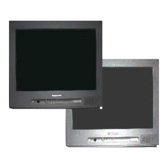
Colour Television
TX-21JT2P
TX-21JT2P/B
Z-M3L Chassis
Video/Audio Terminals:
AV1 IN
Video (21 pin)
Audio (21 pin)
RGB (21 pin)
Audio (RCAx1)
Video (RCAx1)
AV1 OUT
Video (21 pin)
Audio (21 pin)
29kV ± 1kV
High Voltage:
A51QAE320X47P 51cm
Picture Tube:
Audio Output:
3W (Music Power)
8Ω Impedance
Headphones:
8Ω Impedance
3.5mm
Accessories
supplied :
Remote Control
2 x R6 (UM3) Batteries
Dimensions:
Height:
482mm
Width:
506mm
Depth:
484mm
Net weight:
20kg
Specifications are subject to change without notice.
Weights and dimensions shown are approximate.
ORDER No. SM-03002
1V p-p 75Ω
500mV rms 10kΩ
500mV rms 10kΩ
1V p-p 75Ω
1V p-p 75Ω
500mV rms 1kΩ
Advertisement

Summary of Contents for Panasonic TX-21JT2P
- Page 1 ORDER No. SM-03002 Colour Television TX-21JT2P TX-21JT2P/B Z-M3L Chassis SPECIFICATIONS Power Source: 220-240V a.c., 50Hz Video/Audio Terminals: AV1 IN Video (21 pin) 1V p-p 75Ω Power Consumption: Audio (21 pin) 500mV rms 10kΩ RGB (21 pin) Stand-by Power Audio (RCAx1) 500mV rms 10kΩ...
- Page 2 CONTENTS SAFETY PRECAUTIONS ................................. 2 SERVICE HINTS..................................3 ALIGNMENT SETTINGS ................................4 WAVEFORM PATTERN TABLE ............................... 5 BLOCK DIAGRAMS.................................. 6 PARTS LOCATION................................... 7 REPLACEMENT PARTS LIST..............................8 SCHEMATIC DIAGRAMS............................... 12 CONDUCTOR VIEWS ................................17 SAFETY PRECAUTIONS GENERAL GUIDE LINES It is advisable to insert an isolation transformer in the Check each exposed metallic part and check the a.c.
- Page 3 SERVICE HINTS How to remove the rear cover 1. Remove the 5 screws as shown in Fig.2. SCREWS SCREWS Fig. 2. LOCATION OF CONTROLS AV Board CRT Board Main Board Focus Screen...
- Page 4 ALIGNMENT PROCEDURE AND OPTION SETTING Entering SERVICE mode Service mode is entered by selecting the “mute” remote key and local “down” simultaneously with the sharpness DAC set to Minimum and programme position 99 selected. Service mode 2 is selected by pressing the Recall remote key while in service mode 1. Service mode navigation - Up /Down remote keys :cycle through the service items available.
- Page 6 PARTS LOCATION NOTE: The numbers on the exploded view below refer to the mechanical section of the Replacement Parts List. This diagram is used for representative purposes only.
- Page 7 028R200015 DEGAUSS COIL D506 MTZJT-775.6B DIODE 043221021F F.B.T. D507 MTZJT-771.8B ZENER DIODE 0G650809 AC POWER CORD D508 SB290S DIODE 7235760001 PANASONIC BADGE D509 MA165TA5 DIODE A3L917D010K MAIN P.C.B. D510 D28F30DF60 DIODE A51QAE320X47 C.R.T. D511 MTZJT-771.8B ZENER DIODE EUR511300 REMOTE CONTROL...
- Page 8 Cct Ref Parts Number Description Cct Ref Parts Number Description 100 Ω Q512 TPAAB05001 TRANSISTOR R114 ERJ6GEYJ101 S.M.CARB 0.1W 220 Ω Q513 TNAAB05003 TRANSISTOR R115 ERJ6GEYJ221 S.M.CARB 0.1W 15K Ω Q601 2SC2412 TRANSISTOR R116 ERJ6GEYJ153 S.M.CARB 0.1W 3K3 Ω Q602 2SC2412 TRANSISTOR R117...
- Page 9 Cct Ref Parts Number Description Cct Ref Parts Number Description 5K6 Ω 1K Ω R606 ERJ6GEYJ562 S.M.CARB 0.1W R807 ERJ6GEYJ102 S.M.CARB 0.1W 1K Ω 1K Ω R607 ERJ6GEYJ102 S.M.CARB 0.1W R808 ERJ6GEYJ102 S.M.CARB 0.1W 3K9 Ω 1K Ω R608 ERJ6GEYJ392 S.M.CARB 0.1W R809...
- Page 10 Cct Ref Parts Number Description Cct Ref Parts Number Description 220nF C601 ECQV1H224JL3 FILM J801 CVT3275-5101 CRT SOCKET 100µF C602 ECA1CM101B ELECT J1001 HTJ-035-28A RCA JACK 0.1µF C603 CS0RB0315K CERAMIC SWITCHES 220nF C604 ECQV1H224JL3 FILM SW101 EVQ21505R SWITCH 2.2nF C605 ECKC1H222J CERAMIC SW102...
- Page 11 SCHEMATIC DIAGRAMS FOR MODEL TX-21JT2P TX-21JT2P/B (Z-M3L CHASSIS) IMPORTANT SAFETY NOTICE Components identified by mark have special characteristics important for safety. When replacing any of these components, use only manufacturers' specified parts. NOTE RESISTOR All resistors are carbon ¼W resistor, unless marked otherwise.
- Page 16 PRINTED CIRCUIT BOARDS MAIN/CRT/AV (INSERTED PARTS) SOLDER SIDE SW501 FH502 F501 FH501 CP402 C535 CP501 R506 R504 C501_2 D101 R522 R523 C507 L501 R503 D507 D509 W017 W062 OS101 C509 Q502 W034 TH501 D525 W007 W033 R524 D520 T502 T501 C526_2 D402 D512...
- Page 17 PRINTED CIRCUIT BOARDS MAIN/CRT/AV (CHIP MOUNTED PARTS) SOLDER SIDE R652 R609 C650 Q602 R610 C656 IC199 R806 R656 R805 C108 Q609 C648 R804 C001 R005 R008 R110 C655_1 C618 R111 C617 R608 R606 R605 C606 Q601 R607 R651 Q606 R627 R623 R704 Q607...


Need help?
Do you have a question about the TX-21JT2P and is the answer not in the manual?
Questions and answers