Table of Contents
Advertisement
Quick Links
Advertisement
Table of Contents

Subscribe to Our Youtube Channel
Related Manuals for Biral RWS Series


Summary of Contents for Biral RWS Series
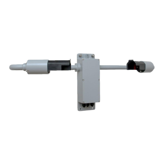
- Page 1 RWS Series Visibility Weather Sensors QUICK START GUIDE RWS-20...
- Page 2 The information contained in this manual (including all illustrations, drawings, schematics and parts lists) is proprietary to BIRAL. It is provided for the sole purpose of aiding the buyer or user in operating and maintaining the instrument. This information is not to be used for the manufacture or sale of similar items without written permission.
-
Page 3: Table Of Contents
Thank you for choosing Biral as your supplier of Road Weather Sensors This guide is intended to get your RWS-20 sensor installed and working as quickly as possible with the most common (Default) settings, and is intended for people who are familiar with installing electrical equipment. -
Page 4: In The Box
1 IN THE BOX The sensor is securely packed in an appropriate shipping container. Should the contents be damaged, please inform Biral at the earliest opportunity. In the box with your RWS sensor, you will find: Part Identification Biral part number ‘U’... -
Page 5: Sensor Features
2 SENSOR FEATURES The RWS sensor can be configured to suit different requirements Standard features Configurable Default Additional optional settings option Visibility 10m – 7500m 10m to (600m to 7500m) Serial data RS232 RS422/485 output Baud rate 9600 configurable between 1200 to 57600 baud 0-10v EXCO... -
Page 6: Sensor Connections
3 SENSOR CONNECTIONS To access the connection terminals, you will need to open the RWS sensor, by loosening the captive screws on the front panel. Figure 1: PCB diagram showing J7, J11, J12, and the relay connections For J11 and J12 Connectors, strip back the wire 11mm. This connecting strip is of a lever clamp design. -
Page 7: Connecting Communications
3.2 CONNECTING COMMUNICATIONS The RWS-20 can be operated with either RS232 or RS422 or RS485 communications. It is not possible to operate both the RS232 and the RS422/RS485 together. Use Jumper J7 to select desired communications protocol. Communication Jumper protocol position RS422/RS485 1&2... -
Page 8: Connecting Analogue Outputs
3.3 CONNECTING ANALOGUE OUTPUTS Pin connections for analogue outputs Pin Number Designation Wire size J12/H 0-10V Analogue Output +ve 20-26AWG 0.5-0.13mm J12/I 0-10V Analogue Output -ve 20-26AWG 0.5-0.13mm J12/J 4 – 20mA Analogue Output +ve 20-26AWG 0.5-0.13mm J12/K 4 – 20mA Analogue Output -ve 20-26AWG 0.5-0.13mm J12/L... -
Page 9: Connecting The Ferrites
3.5 CONNECTING THE FERRITES This sensor MUST HAVE FERRITES INSTALLED. Failure to install the supplied ferrite cores may result in inaccurate readings or lost communications The unit is supplied with two clip type ferrites; these are not optional items and must be fitted. -
Page 10: Confirming The Communications
2. Ensure an earth connection to the chassis, and power connected to J11 C&D (9 to 36V, and 0V) 3. Connect to the Biral Sensor interface software using default 9600 baud 4. Apply power to the sensor: If communications are working the sensor will respond with “Biral Sensor Startup”. -
Page 11: Confirming The Outputs
5 CONFIRMING THE OUTPUTS If you wish to test the outputs of the sensor, use the command ‘TEST’ to get the unit to temporarily output foggy and clear conditions, which will allow you to check the analogue outputs and (optional) relay thresholds. Use the CO command before the TEST command to access the TEST command. -
Page 12: Sensor Installation
6 SENSOR INSTALLATION Please consider the following factors when choosing a location for the sensor. Direct and Reflected Light – Care should be taken to ensure that the sensor is situated with the receiver facing away from any direct sunlight (rising and setting sun) and any surfaces which could cause reflections of the IR (Infrared) illumination from the transmitter (for example walls, bridges, trees and people, etc.). -
Page 13: Mounting Details
6.1 MOUNTING DETAILS Any glands not in use should be sealed with the supplied sealing plugs to retain the integrity of the weatherproof housing. The U bolts fit a standard mounting pole of 40-64mm diameter. Figure 6: Mounting details... -
Page 14: Electrical Grounding / Protection
6.2 ELECTRICAL GROUNDING / PROTECTION This sensor MUST BE EARTHED. Failure to install a suitable earth may result in inaccurate readings and / or damage to the sensor. Failure to install an earth when using mains voltages on the relays will make the sensor potentially unsafe. An M6 earth bolt is provided, this is attached to the earth stud. -
Page 15: Maintenance
The windows should be cleaned by gently wiping the windows using a soft clean cloth and water. End of Guide Should you require further information, the RWS user manual is free to download at: http://www.biral.com/technical-support/downloads/manual-downloads/...
Need help?
Do you have a question about the RWS Series and is the answer not in the manual?
Questions and answers