Table of Contents
Advertisement
Quick Links
Advertisement
Table of Contents

Related Manuals for Biral SWS Series


Summary of Contents for Biral SWS Series
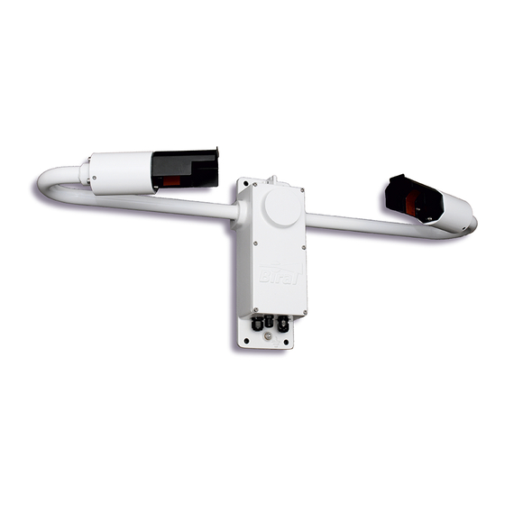
- Page 1 SWS Series Visibility & Present Weather Sensors SWS-050 SWS-100 SWS-200 SWS-250...
- Page 3 The information contained in this manual (including all illustrations, drawings, schematics and parts lists) is proprietary to BIRAL. It is provided for the sole purpose of aiding the buyer or user in operating and maintaining the sensor. This information is not to be used for the manufacture or sale of similar items without written permission.
-
Page 4: Table Of Contents
The sensors covered in this manual ............v Features of the SWS sensors ..............vi Customer satisfaction and After Sales Support ........vii Contacting Biral................... vii Three year warranty ................viii If you need to return the sensor ............viii CE Certification –... - Page 5 PRODUCT OVERVIEW ..............74 SWS Series Visibility and Present Weather Sensors ...... 74 Sensor Features ............... 77 Present Weather Measurements ..........78 Visibility Measurements ............. 78 Precipitation Measurements ............80 Sensor Specifications ..............88 Sensor Characteristics ............... 90 Digital Communication Interface ..........93 Analogue Outputs ..............
- Page 6 Table 13 SWS-250 Operating data message format ........ 45 Table 14 METAR codes ................ 47 Table 15 Message extension for ALS-2 ..........49 Table 16 Commands for SWS series of sensors ........53 Table 17 Command R? response............56 Table 18 Sensor responses ..............58 Table 19 Visibility measurement capabilities ..........
-
Page 7: The Sensors Covered In This Manual
General Information The sensors covered in this manual: Sensor Model Capability SWS-050 Visibility Obstruction to Vision SWS-100 Visibility Precipitation type identification 1 Fault relay switch 1 Relay for visibility 1 Relay for precipitation, window contamination or visibility SWS-200 Visibility Precipitation type identification 1 Fault relay switch 1 Relay for visibility 1 Relay for precipitation, window contamination or visibility... -
Page 8: Features Of The Sws Sensors
Thank you for choosing Biral as your supplier of present weather sensors A great deal of time has been invested at Biral to offer the best combination of sensor performance and value and almost three decades of experience and knowledge have been incorporated into the SWS series. We are confident that they will provide you with many years of accurate operation. -
Page 9: Contacting Biral
(equally, if you have any positive experiences you would like to share). After Sales Support Biral offers support by telephone and email for the lifetime of these sensors, even if there has been a change of ownership, so please get in touch if you require help. -
Page 10: Three Year Warranty
The customer is responsible for the shipping costs. CE Certification - Safety All Biral’s SWS sensors comply with the requirements for CE marking. Once installed, it is the user’s responsibility to ensure that all connections made to the sensor comply with all Local and National safety requirements. -
Page 11: Sensor Set-Up
Note: Many of the tests specified within this manual require the use of a PC or equivalent. To achieve the two-way serial communication required, Biral recommends the use of a PC running the Biral Sensor Interface Software. If this software is not available, use a terminal program - for example Windows® Hyper Terminal™. -
Page 12: Step 1 - Unpacking The Sensor
Sensor Set-up Section 1 1.1 STEP 1 - Unpacking the Sensor The sensor is packed in a foam filled shipping container and is fully assembled ready for use. The sensor is delivered with: U-bolts for pole mounting SWS sensor in 2 off ferrites for cable foam-filled EMC protection... -
Page 13: Step 2 - Electrical Connections
Section 1 Sensor set-up 1.2 STEP 2 - Electrical Connections ALL ELECTRICAL CONNECTIONS SHOULD BE COMPLETED BEFORE APPLYING POWER TO THE SENSOR 1.2.1 Cables Unless purchased as an option the sensor is not supplied with power and data cables. For the power and data cables we recommend you use screened, twisted pair cables in a suitable outdoor EMC and UV resistant sheath (this is particularly important for the data cables). -
Page 14: Figure 1-2 Cable Glands
Sensor Set-up Section 1 Unused Glands Any glands not in use should be sealed with the supplied sealing plugs to retain the integrity of the weatherproof housing. 2 small cable glands for cables between 3.5 to 7.00mm diameter 2 larger glands for cables between 4.5 to 10mm diameter Figure 1-2 Cable Glands... -
Page 15: Table 1 Pin Connections For Power Supply
Section 1 Sensor set-up For ease of assembly it is recommended that 24AWG stranded (7/32) or solid wires are used, or equivalent. These are ideal for the low power requirements of the system. However, the connectors can accommodate wires from 20AWG down to 26AWG (0.5 to 0.13 mm ), of solid or stranded construction. -
Page 16: Figure 1-4 Location Of J7, Rs232/422/485 Select
Sensor Set-up Section 1 Pin Connections for RS232 or RS422/RS485 Signal Interfaces The sensors can be operated with RS232 or RS422 or RS485 communications. It is not possible to operate both the RS232 and the RS422/RS485 together. See Table 2 and Table 3 for full connection details. Pin Number Designation J12/A... -
Page 17: Figure 1-5 Relay Connections
Section 1 Sensor set-up 1.2.4 Connecting the relays The unique ability to switch equipment using a visibility (fog) relay and / or a precipitation (rain, snow) relay is a feature of the SWS-100 and SWS-200 sensors. For example you can set relays to automatically switch a speed reduction sign when visibility is below 100 m and then switch an additional ‘danger of aquaplaning’... -
Page 18: Table 4 Connections For 0-10V Analogue Output
Sensor Set-up Section 1 1.2.5 Pin connections for 0-10 V analogue output An analogue output representing Meteorological Optical Range (MOR) as a signal between 0 and 10V is standard on the SWS-100 and SWS-200 sensors. The connections are as given in Table 4. Pin Number Designation J12/H... -
Page 19: Figure 1-6 Als-2 Connecting System
Section 1 Sensor set-up 1.2.8 Optional ALS-2 Connections Any of the SWS sensors can be supplied with an ambient light sensor, model ALS- 2. This sensor will be connected directly to the SWS sensor, drawing its power from the sensor supply. If required, the ALS-2 will be fitted with hood heaters which will operate when the sensor hood heaters operate. -
Page 20: Step 3 - Equipment Test
Connect sensor earth lug to earth (this may not be necessary but can help prevent communication errors with certain PCs). 2. Connect the signal cable to a PC running the Biral Sensor Interface Software. If this is not available, use a terminal program - for example Windows®... - Page 21 Section 1 Sensor set-up 1. Turn the local power source "ON". If communications are working the sensor will respond with “Biral Sensor Startup”. 2. Check Data Transmission To Sensor: Send the command from the PC terminal to the sensor: The sensor will respond with its Remote Self-Test & Monitoring Message.
-
Page 22: Step 4 - Configuration Options
“OP” or “OS”. Each of these is detailed below in sections 1.4.3 to 1.4.12. An alternative method of configuring the sensor is to use the Biral Sensor Interface Software. The “Sensor Settings” tab provides an easy method of viewing or changing the settings. - Page 23 Section 1 Sensor set-up 1.4.2 Date and Time Stamp in data string By default, the date and time stamp is not included at the start of the data string. This is controlled by the Options Word setting; see 1.4.1. To enable Date and Time stamp The sensor can be configured to generate messages with the date and time string by setting the least significant bit in the options word: 1.
- Page 24 Sensor Set-up Section 1 - is the month (01..12) - is the year (00..99) The sensor will respond with 'OK'. %ST sets the time. The format of the command is: %STHHMMSS where: - is the hours in 24 hour clock (00..23) - is the minutes (00..59) - is the seconds (00..59) The sensor will respond with 'OK'.
- Page 25 Section 1 Sensor set-up For any message: C1 ... Cm <cksum><crlf> The calculation is as follows: = cksum − IF <cksum> = 8 THEN <cksum> = 119 IF <cksum> = 10 THEN <cksum> = 117 IF <cksum>...
- Page 26 Sensor Set-up Section 1 Start: ‘:’ (3A Hex). Sensor Address: 2 Character address field. Data: As standard SWS message format, see Section 2. LRC Checksum: 2 Characters - Longitudinal Redundancy Check. End: 2 Characters - Carriage return + Line Feed. Start The ‘:’...
- Page 27 See paragraph 1.4.6 for full instructions for setting this configuration. Note: When RS485 communications are enabled the sensor will not output the “Biral Sensor Startup” message on power up and reset. STEP 4 - Configuration Options...
- Page 28 Sensor Set-up Section 1 1.4.5 Sensor Addressing – RS485 sensors only To use addressable RS485 communication each sensor must have a unique address in the range 0-99. By default, the sensor address is set to 0. Querying the sensor address To query the sensor address, send the command: ADR? The sensor should respond with the address: e.g.
- Page 29 Section 1 Sensor set-up 1.4.7 Optional hood heater operating setting The sensor can be set to have the hood heaters disabled, or for them to work automatically. The default setting, for sensors with fitted hood heaters, is for automatic hood heater operation. To check which configuration is programmed send the message: OSHH? The sensor will send the reply:...
- Page 30 Sensor Set-up Section 1 1.4.9 Baud Rate Configuration Default communication parameters are 9600, 8 data bit, 1 stop bit, no parity, and no flow control. The baud rate may be changed if required as follows. Send Where n is a number from 1 to 7. Just typing %B will bring up the different baud rate options: SELECT REQUIRED BAUDRATE BY TYPING %B(NUMBER) 1..1200 BAUD...
-
Page 31: Table 7 Relay Configuration
Section 1 Sensor set-up 1.4.10 Configuring the Relays Failure to install a protective earth will make the unit potentially unsafe when using the relays to switch hazardous voltages. Relays are fitted as standard on the SWS-100 and SWS-200 sensors. Relays are not available on the SWS-050 and SWS-250 sensors. - Page 32 Sensor Set-up Section 1 where is the relay number (either 1 or 2) xx.xx is the threshold level in km. Range 0.10 to 20.00km. e.g. to set the threshold for relay 1 to 1km send the command: RL1,1.00. To read the relay switching delay To ensure the relays do not continually switch, for example when the visibility fluctuates around the switching point, a time delay is provided.
- Page 33 Section 1 Sensor set-up 1.4.11 Configuring the MOR Output In the factory default setting the Meteorological Optical Range (MOR) values output in the data messages are expressed in kilometres to a resolution of 10m. The output can also be expressed in metres to a resolution of 1m or kilometres to a resolution of 1m.
- Page 34 Sensor Set-up Section 1 Querying the EXCO output Setting To query the EXCO output setting, send the PE? Command. The sensor will respond with five characters as shown below: 00000 Default Setting, forward scatter EXCO or no EXCO value 00001 TEXCO output.
-
Page 35: Step 5 - Installation
Section 1 Sensor set-up 1.5 STEP 5 - Installation Please consider the following factors when installing the sensor: (1) Siting considerations. (2) Height of the sensor above ground. (3) Orientation of the sensor. (4) Mounting the sensor. (5) Electrical grounding. Each of these factors is covered in more detail below: 1.5.1 Siting Considerations Pollutants –... -
Page 36: Table 8 Sensor Height Above Ground
Sensor Set-up Section 1 1.5.2 Height Above Ground: The optimum height at which to mount the sensor depends on the application. The table below shows recommended heights. Application Typical height Comment Recommended height for the sensor sample volume is the Highway fog-warning 1.5 to 2 metres average distance of a vehicle... -
Page 37: Figure 1-7 Sws-050 And Sws-100 Orientation
Section 1 Sensor set-up head 34˚West of South, and for the SWS-050 and SWS-100, point the forward scatter receiver directly due South. Figure 1-7 SWS-050 and SWS-100 Orientation Figure 1-8 SWS-200 and SWS-250 Orientation STEP 5 – Installation... -
Page 38: Figure 1-9 U-Bolt Mounting Method
Sensor Set-up Section 1 1.5.4 Mounting the Sensor: On a pole Two stainless steel U-bolts and saddles are provided for securing the sensor to the top of a mast, see Figure 1-9 U-Bolt Mounting Method. The two V-block saddles oppose the U-bolt, thus providing a secure grip on the mast. The sensor can be mounted on a galvanised steel pipe or heavy walled aluminium tube with an outer diameter between 40 to 64 mm. - Page 39 Section 1 Sensor set-up 1.5.5 Electrical Grounding This product MUST BE EARTHED. Failure to install a suitable earth may result in inaccurate readings and / or damage to the product and attached equipment. Failure to install an earth will make the unit potentially unsafe when using the relays to switch hazardous voltages.
-
Page 40: Step 6 - Test And Commissioning
1. Connect the power-input cable to a local power source (do not turn power source on). 2. Connect the signal wires to a PC running the Biral Sensor Interface Software. If this is not available, use a terminal program - for example Windows®... -
Page 41: Table 9 Remote Self-Test And Monitoring Check Fields
Section 1 Sensor set-up 4. Turn the local power source "ON". If communications are working the sensor will respond with “Biral Sensor Startup”. 5. Check Data Transmission To Sensor: Send the command from the PC terminal to the sensor: The sensor will respond with its Remote Self-Test & Monitoring Message. - Page 42 Section 1 1.6.4 Calibration Check The sensor is fully calibrated before it leaves Biral. However, if you would like to carry out a user confidence calibration check please follow the calibration check procedure in section 5 to ensure that the MOR value changes i.e. the sensor responds to changes in visibility.
- Page 43 Section 1 Sensor set-up Available PW Codes: SWS-050: 00,04,10,27,30 SWS-100, SWS-200 & SWS-250: 00,04,10,27,30,40,50,51,52,53,60,61,62,63,70,71,72,73,89 An invalid code will return code 00 in the sensor message string. Note: The available codes may not be valid for the sensor in question and not all codes are available.
- Page 44 Sensor Set-up Section 1 CONGRATULATIONS YOUR SENSOR SHOULD NOW BE FULLY CONFIGURED, TESTED AND INSTALLED READY FOR USE THE REMAINDER OF THIS MANUAL COVERS: - STANDARD DATA MESSAGES - COMMANDS AND RESPONSES - OPERATIONAL AND MAINTENANCE PROCEDURES - CALIBRATION CHECK AND RE-CALIBRATION PROCEDURE - SENSOR DETAILS AND SPECIFICATIONS STEP 6 –...
-
Page 45: Standard Operating Data
Section 2 Standard Operating Data 2 STANDARD OPERATING DATA When in standard mode a data message will be output from the sensor every measurement period (default 60 seconds). When in polled mode the same message is output only in response to the D? command. The operating mode is checked by sending command “OSAM?”. -
Page 46: Standard Operating Data Message For The Sws-050
Standard Operating Data Section 2 2.1 Standard Operating Data Message for the SWS-050 The data message format for the SWS-050 is: <Date>,<Time>,SWS050,NNN,XXX,AA.AA KM,BB,CCC.CC,DDD, <cs>crlf Note: < > denotes an optional field. MESSAGE MEANING <Date> Optional Date string in the form DD/MM/YY. <Time>... - Page 47 Section 2 Standard Operating Data A typical data message from an SWS-050 sensor in default configuration is as follows: SWS050,001,060,00.14 KM,30,021.43,XOO A data message with the sensor configured for 1m resolution MOR is as follows: SWS050,001,060,000142 M,30,021.43,XOO Note 1: The format and resolution of the MOR value reported can be configured using the KMn command, see section 1.4.11.
-
Page 48: Standard Operating Data Message For The Sws-100
Standard Operating Data Section 2 2.2 Standard Operating Data Message for the SWS-100 The data message format is: <Date>,<Time>,SWS100,NNN,XXX,AA.AA KM,BB.BBB,CC,DD.D C,EE.EE KM,FFF,<GGG.GG><cs>crlf Note: < > denotes an optional field. MESSAGE MEANING <Date> Optional Date string in the form DD/MM/YY. <Time> Optional Time string in the form HH:MM:SS. -
Page 49: Table 11 Sws-100 Operating Data Message Format
Section 2 Standard Operating Data MESSAGE MEANING Self-test and Monitoring (see section 4.2): F F F O = Other self-test values OK. X = Other self-test faults exist. O = Windows not contaminated. X = Window contamination warning – cleaning recommended. F = Window contamination fault –... -
Page 50: Standard Operating Data Message For The Sws-200
Standard Operating Data Section 2 2.3 Standard Operating Data Message for the SWS-200 The data message format is: <Date>,<Time>,SWS200,NNN,XXX,AA.AA KM,BB.BBB,CC,DD.D C,EE.EE KM,FFF,<GGG.GG>,<cs>crlf Note: < > denotes an optional field. MESSAGE MEANING <Date> Optional Date string in the form DD/MM/YY. <Time> Optional Time string in the form HH:MM:SS. -
Page 51: Table 12 Sws-200 Operating Data Message Format
Section 2 Standard Operating Data MESSAGE MEANING Self-test and Monitoring (see section 4.2): F F F O = Other self-test values OK. X = Other self-test faults exist. O = Windows not contaminated. X = Window contamination warning – cleaning recommended. F = Window contamination fault –... -
Page 52: Standard Operating Data Message For The Sws-250
Standard Operating Data Section 2 2.4 Standard Operating Data Message for the SWS-250 The data message format is: <Date>,<Time>,SWS250,NNN,XXXX,AA.AA KM,CC,W ,DD,EEEEE, FFF.FFF,GG.GG KM,HHH.HH, III.II,±JJJ.JJ,KKK.K C,±LLLLL,MMM, NNNN,OO.OOOO,PPP<cs>crlf Note: < > denotes an optional field. MESSAGE MEANING <Date> Optional Date string in the form DD/MM/YY. <Time>... - Page 53 Section 2 Standard Operating Data MESSAGE MEANING Heavy Drizzle Slight Drizzle and Rain Moderate or Heavy Drizzle and Rain Slight Rain Moderate Rain Heavy Rain Slight Rain and Snow Moderate or Heavy Rain and Snow Slight Snow Moderate Snow Heavy Snow Slight Ice Pellets Moderate Ice Pellets Heavy Ice Pellets...
- Page 54 Standard Operating Data Section 2 MESSAGE MEANING FFF.FFF Precipitation Rate (mm/hr). Meteorological Optical Range (km). This is the instantaneous value. GG.GG KM See Note 1. HHH.HH Total Exco (km ). This is the averaged value. III.II Transmissometer equivalent EXCO (km ±JJJ.JJ Back Scatter Channel Exco (km ).
-
Page 55: Table 13 Sws-250 Operating Data Message Format
Section 2 Standard Operating Data MESSAGE MEANING ALS Self-Test and Monitoring If ALS not fitted set to FFF, See section 4.2. O = Other self-test values OK. X = Other self-test faults exist. O = windows not contaminated. X = window contamination warning – cleaning recommended. F = Window contamination fault –... - Page 56 Standard Operating Data Section 2 2.4.1 METAR Codes CODE METAR MEANING NUMBER CODE Not Ready (first 5 minutes from restart) No significant weather observed Haze, visibility greater than or equal to 1km Diamond Dust. Fog in last hour but not at time of observation Precipitation in last hour but not at time of observation Drizzle in last hour but not at time of observation Rain in last hour but not at time of observation...
-
Page 57: Table 14 Metar Codes
Section 2 Standard Operating Data CODE METAR MEANING NUMBER CODE Rain, not freezing, moderate Rain, not freezing, heavy -RASN Rain (or Drizzle) and Snow, slight RASN Rain (or Drizzle) and Snow, moderate +RASN Rain (or Drizzle) and Snow, heavy Snow, slight Snow, moderate Snow, heavy Ice Pellets, slight... - Page 58 Standard Operating Data Section 2 SWS-250 WMO 4680 and METAR Codes The SWS-250 reports weather phenomena using both WMO Table 4680 and METAR codes (WMO Table 4678). As there is not always a METAR code associated with the WMO Table 4680 code the following logic is used to determine what codes to report: Field cc The sensor reports the highest Table 4680 number...
-
Page 59: Data Message Variations For Als-2
Section 2 Standard Operating Data 2.5 Data Message Variations For ALS-2 For SWS sensors fitted with an Ambient Light Sensor, ALS-2, the data output strings are identical to the standard message with the following appended to the message, prior to the optional checksum<cs> and the carriage return and line feed <crlf>. -
Page 60: Commands And Responses
Commands and Responses Section 3 3 COMMANDS AND RESPONSES 3.1 Sensor Commands Note: All commands should be terminated with <Carriage Return> and <Line Feed> (<crlf>, see paragraph 1.3). Commands marked with * cause the sensor to restart. Commands marked with must be preceded by the CO command. - Page 61 Section 3 Commands and Responses Applicability SWS- Command Function Response 050 100 200 250 Set sensor identification number IDx* displayed in data message. √ √ √ √ Range x = 0 to 999. (Default = 1). See section JRO? Check Current Relay Configuration. √...
- Page 62 Commands and Responses Section 3 Applicability SWS- Command Function Response 050 100 200 250 See section Set EXCO output configuration. √ √ √ 1.4.12 Query program version message. SI xxxx.yy √ √ √ √ Send remote self-test and monitoring See section √...
-
Page 63: Table 16 Commands For Sws Series Of Sensors
√ √ √ √ Table 16 Commands for SWS series of sensors indicates that these commands are only applicable if the relay option has been √ taken, which is only available on the following models: SWS100 & SWS200. Sensor Commands... - Page 64 Commands and Responses Section 3 3.1.1 Commands A? and AC – Precipitation Accumulation These commands apply only to the SWS-200 and SWS-250. The sensor records the total amount of precipitation detected in a 24-hour period. The 24-hour period starts when the sensor is powered or when the accumulated precipitation value is reset.
- Page 65 Section 3 Commands and Responses 3.1.2 Command M? – Send Precipitation message This command is only available in the SWS-250 sensor. The sensor responds by sending a precipitation matrix accumulated over the last five measurement periods. This is a matrix of 16 rows with up to 21 readings, each being the number of precipitation particles of that specific size and velocity.
-
Page 66: Table 17 Command R? Response
Commands and Responses Section 3 3.1.3 Command R? - Send Remote Self-Test and Monitoring Message Example response: _100,2.509,24.1,12.3,5.01,12.5,00.00,00.00,100,105,107,00,00,00,+021.0 ,4063 The various fields in the response are as follows: Field Range / Value Description Field 1: Space The message starts with a space. Field 2: Heater state and error flags. - Page 67 Section 3 Commands and Responses 3.1.4 Command T? - Send Sensor Times Message Response: aaaa,bbbb,ccccc,dddd aaaa: Measurement interval for each operational data message (10 to 300 seconds) (default = 60). bbbb: Auxiliary measurement sample period - time between measurement of peripheral signals during measurement interval.
-
Page 68: Sensor Responses
Commands and Responses Section 3 3.2 Sensor Responses RESPONSE MEANING The command was not understood by the sensor. Check the text of the BAD CMD command and re-send. An error was detected in a character in the command. Re-send the COMM ERR command. -
Page 69: Maintenance Procedures
Maintenance Procedures 4 MAINTENANCE PROCEDURES The SWS series of sensors require very little maintenance. The following sections detail the checks that are advisable to ensure continued good operation of the sensor. The frequency of these checks depends upon the location and environmental conditions under which the sensor operates. -
Page 70: Figure 4-1 Hood Heater
When the temperature is above the 4°C the heaters will be switched off but may be controlled using a PC running the Biral Sensor Interface Software. If this is not available, use a terminal program - for example Windows® HyperTerminal™. -
Page 71: Self-Test Codes
Section 4 Maintenance Procedures The SWS-050 and SWS-250 sensors are additionally fitted with receiver window monitors. These monitor the forward scatter window and, if fitted, the back scatter window. This provides better accuracy if there is likely to be different contamination on each window. - Page 72 Maintenance Procedures Section 4 visibility reading is still corrected using this contamination figure, the accuracy may deteriorate as the contamination increases. The windows require cleaning. The values of WT and WF can be queried and set using the WT and WF commands as described in section 3.1.
-
Page 73: User Confidence Checks
Maintenance Procedures 4.3 User Confidence Checks The following user confidence checks require bi-directional communications with a PC running the Biral Sensor Interface Software. If this is not available, use a terminal program - for example Windows HyperTerminal. It is suggested that these should be carried out at least every year, to provide continuing confidence in the correct operation of the system. -
Page 74: Figure 4-2 Transmitter Hood With White Card
Maintenance Procedures Section 4 white card Figure 4-2 Transmitter Hood with White Card Step 5. Send the command: R? Step 6. Verify that the 'Transmitter Window Contamination' field value is much greater than 10 (eg 99). Step 7. Remove the white card. Receiver Window Monitor(s) This procedure is used for the forward scatter receivers on the SWS-050 sensor (optional on the SWS-100) and both the forward and back scatter receivers on the... - Page 75 Section 4 Maintenance Procedures Step 8. Verify that the 'Forward (or Back) Scatter Receiver Window Contamination' field value is much greater than 10 (i.e. 99). Step 9. Remove the white card. Note: A delay of 5 minutes is introduced between a window contamination threshold being exceeded and the appropriate flag being set in the data message.
-
Page 76: Calibration Procedures
Calibration Procedures Section 5 5 CALIBRATION PROCEDURES This section explains how to CHECK the calibration of the sensor and ONLY IF NECESSARY how to recalibrate it. ALL THE PROCEDURES IN THIS SECTION REQUIRE A SWS CALIBRATION KIT ENSURE THE CORRECT MODEL AND REVISION OF CALIBRATION KIT IS AVAILABLE. -
Page 77: Calibration Check
Black Silver 5.2 Calibration Check The following instructions show how to check the calibration of a SWS series sensor. This procedure can only be completed with: A SWS Calibration Kit. Connection to a PC running the Biral Sensor Interface Software, or, if this is not available, terminal emulation software (such as Windows ®... -
Page 78: Figure 5-1 Assembly Of Calibration Reference Plaque
Calibration Procedures Section 5 CALIBRATION CHECK NOTES PLEASE READ THESE NOTES BEFORE CONTINUING The MOR (Meteorological Optical Range or visibility) values depend heavily on the location and prevailing weather conditions and should only be carried out with the sensor: 1. MOUNTED OUTSIDE AND ON A CLEAR DRY DAY (VISIBILITY>10KM) 2. - Page 79 Calibration Procedures Section 5 Note: All commands should be terminated with <Carriage Return> and <Line Feed> <crlf>, (see Paragraph 1.3). STEP 1: Clean all windows on the sensor using a mild detergent solution or pure alcohol (propanol) and soft cloth or tissue, preferably lens tissue. Check the cleanliness using a portable light if possible.
- Page 80 Calibration Procedures Section 5 STEP 11: Wait for the fifth (5 ) data message from the sensor. Send the command “BT? <crlf>”. Verify that the response value is within ±10% of the forward scatter calibration value assigned to the Calibration Reference Plaque.
-
Page 81: Sensor Re-Calibration
Calibration Procedures Section 5 5.3 Sensor Re-Calibration RE-CALIBRATING THE METEOROLOGICAL OPTICAL RANGE SHOULD ONLY BE CARRIED OUT IF THE SENSOR HAS FAILED A CORRECTLY PERFORMED USER CONFIDENCE CHECK WARNING ERRORS DURING THIS RE- CALIBRATION PROCEDURE WILL CAUSE THE SENSOR TO GIVE INCORRECT DATA BEFORE CONTINUING ENSURE THAT THE SENSOR: 1. - Page 82 ±5% of the backscatter calibration value of the plaque then the sensor is within its calibration limits. The sensor can be returned to its operational configuration with confidence. If the values are outside these limits carefully repeat the calibration procedure. If the limits are again exceeded contact Biral. Sensor Re-Calibration...
-
Page 83: Precipitation Amount Calibration
Calibration Procedures Section 5 5.4 Precipitation Amount Calibration Note: All commands should be terminated with <Carriage Return> and <Line Feed> <crlf>, (see Paragraph 1.3). This section is only applicable to models SWS-200 and SWS-250. This process provides for adjusting the calibration factor of the sensor precipitation measurement. -
Page 84: Product Overview
6 PRODUCT OVERVIEW 6.1 SWS Series Visibility and Present Weather Sensors There are five models in the SWS series of present weather sensors, four of which are covered in this manual, they are SWS-050, SWS-100, SWS-200 and SWS-250. They all use the same basic opto-mechanical and electronic components and have an optical transmitter and forward scatter receiver. -
Page 85: Figure 6-2 Sws-200 And Sws-250 Capabilities
Section 6 Product Overview Sensor Model Capability SWS-200 Visibility Precipitation type identification 1 Fault relay switch 1 Relay for visibility 1 Relay for precipitation, window contamination or visibility This model has an extra backscatter receiver for: Rain rate Snowfall rate Precipitation accumulation SWS-250 Visibility... - Page 86 Product Overview Section 6 6.1.1 Sensor Components Each sensor has been engineered and manufactured with high-reliability components to provide accurate measurements under all weather conditions. Its rugged aluminium powder-coated construction is intended to serve you in the severest of environmental conditions throughout the long life of the sensor. All models are shipped fully assembled and calibrated.
-
Page 87: Sensor Features
These may be ordered if required. The length must be specified at time of order. Ambient Light Sensor The Biral ALS-2 ambient light sensor can be readily integrated with any SWS sensor. This provides an accurate measure of the prevailing apparent light intensity. -
Page 88: Present Weather Measurements
Product Overview Section 6 Ease of Maintenance and Calibration: Routine maintenance, including a check on calibrations, is performed in a matter of a few minutes. A re-calibration, if required takes only slightly longer and is easily performed by one person. 6.3 Present Weather Measurements 6.3.1 Present Weather Definition The term "Present Weather"... -
Page 89: Table 19 Visibility Measurement Capabilities
Section 6 Product Overview output message. If MOR is greater than 10 km, no obstruction to vision is indicated. Note: Definitions of haze and fog may change dependent on the country of use. These definitions can be adjusted at time of manufacture for SWS200 and SWS250 sensors, in conjunction with the precipitation intensity definitions, see section 6.5.2 for details. -
Page 90: Precipitation Measurements
Note: If a sensor is intended for installation in a country where the definitions of precipitation intensity differ from the U.K. definitions, it is possible for the sensor to be produced with the appropriate definitions installed. BIRAL must be informed of this requirement at the time of order. -
Page 91: Table 21 Uk Precipitation Intensity Definitions
Section 6 Product Overview UK Precipitation Definitions Based on CAA CAP 746 ‘Requirements for Meteorological Observations at Aerodromes’ Drizzle Slight A trace to 0.26mm/hour. Moderate Greater than 0.26mm/hour to 1.0 mm/hour. Heavy More than 1.0 mm/hour. Rain Slight A trace to 1.0 mm/hour. Moderate Greater than 1.0 mm/hour to 3.99 mm/hour. -
Page 92: Table 22 Sws-050 Wmo Codes
Product Overview Section 6 6.5.3 Precipitation Reporting Any precipitation identified is reported according to the present weather codes from the WMO table 4680 (Automatic Weather Station). Additionally, the SWS- 250 reports METAR present weather codes, see Table 14 METAR codes. The WMO codes utilised by each SWS sensor model are listed below. -
Page 93: Table 24 Sws-200 Wmo Codes
Section 6 Product Overview Present Weather Codes – SWS-200 Code Description Not Ready (first 5 measurement periods from restart). No Significant weather observed. Haze or smoke. Fog. Indeterminate precipitation type. Light Drizzle. Moderate Drizzle. Heavy Drizzle. Light Rain. Moderate Rain. Heavy Rain. - Page 94 Product Overview Section 6 Present Weather Codes – SWS-250 Code METAR Description Not Ready (first 5 minutes from restart). No significant weather observed. Haze, visibility greater than or equal to 1km. Diamond Dust. Fog in last hour but not at time of observation. Precipitation in last hour but not at time of observation.
-
Page 95: Table 25 Sws-250 Wmo And Metar Codes
Section 6 Product Overview Code METAR Description +RASN Rain (or Drizzle) and Snow, heavy. Snow, slight. Snow, moderate. Snow, heavy. Ice Pellets, slight. Ice Pellets, moderate. Ice Pellets, heavy. Snow Grains . Ice Crystals. -SHRA Rain Showers, slight. SHRA Rain Showers, moderate. +SHRA Rain Showers, heavy . - Page 96 Section 6 6.5.4 Precipitation Recognition Matrix The SWS series of sensors measure the amplitude and duration of the light pulse created by each precipitation particle as it falls through the sample volume. From the amplitude and duration it then determines the particle size and velocity. The...
-
Page 97: Figure 6-3 Precipitation Recognition Matrix
Section 6 Product Overview Figure 6-3 Precipitation Recognition Matrix Product Overview... -
Page 98: Sensor Specifications
Product Overview Section 6 6.6 Sensor Specifications The specifications for all versions of the SWS sensor series are summarised in the following pages. Where certain specifications are only applicable to certain models within the range, this is stated within that table. Visibility Measurement Function Details... -
Page 99: Table 28 Precipitation Measurement
Section 6 Product Overview Precipitation Measurements (Not SWS-050) Function Details Detection Threshold: Rain 0.015mm/hr (0.0006 in/hr.) Detection Threshold: Snow 0.0015mm/hr (0.00006 in/hr.) 0 Equivalent) Rain Rate (Maximum) ~ 500mm/hr (20 in/hr.) Table 28 Precipitation Measurement Maintenance Function Details MTBF (Calculated) 52,500 hrs (6 years). -
Page 100: Sensor Characteristics
Product Overview Section 6 6.7 Sensor Characteristics Physical Function Details Scattering Angle 45 with ± 6 cone angle Sample Volume 400 cm Weight SWS-050 and SWS-100 3.8Kg (4.3Kg including pole mounting kit) SWS-200 and SWS-250 4.0Kg (4.5Kg including pole mounting kit Length 0.81 m Table 30 Physical Characteristics... -
Page 101: Table 34 Power Requirements
Section 6 Product Overview Power Requirements Function Details Power Source Sensor (Voltage) 9V to 36V DC (24V typical) Power Source Sensor (Power) 3.5 W Power Source Hood Heaters 24V DC or AC (Voltage) SWS-050 and SWS-100 24W Power Source Hood Heater (Power) SWS-200 and SWS-250 36W Additional for ALS-2 option 12W Additional Power for:... -
Page 102: Table 35 Environmental Specifications
Product Overview Section 6 Environmental Function Details Sensor Operating Temperature -40C to +60C Range Altitude 0 to 20,000 ft Precipitation All weather Humidity 0 to 100% Protection Rating IP66/67 CE Certified √ EMC Compliant EN61326-1 2006 RoHS and WEE Compliant √... -
Page 103: Digital Communication Interface
Section 6 Product Overview 6.8 Digital Communication Interface Communication Protocol Function Details Interface Type RS232C, (Full Duplex) User Selectable RS422/RS485 Table 36 Communication Protocols Communication Parameters: Function Details Baud Rates (User selectable) 1200 Baud to 57K6 Baud (Default 9600 Baud) Data Bits Parity None... -
Page 104: Analogue Outputs
Product Overview Section 6 6.9 Analogue Outputs These are available only on models SWS-100 and SWS-200. Function Details Voltage 0 to 10 Volts out. Equivalent to 0 to MOR MAX. 4 to 20 mA. Equivalent to 0 to MOR (option) Current 0 to 20 mA. -
Page 105: Sensor Remote Self-Test Capabilities
Section 6 Product Overview 6.11Sensor Remote Self-Test Capabilities • Optical Source Power. • Forward Scatter Receiver Sensitivity. • Back Scatter Receiver Sensitivity (not SWS-050 or SWS-100). • Transmitter Window Contamination. • Forward Scatter Receiver Window Contamination (optional on SWS-100 and SWS-200). -
Page 106: Sws Sensors - External Dimensions
Product Overview Section 6 6.12SWS Sensors – External Dimensions All SWS sensors have dimensions as shown below. The diagrams show the SWS- 200 and SWS-250 versions. The SWS-050 and SWS-100 versions do not have the backscatter hood and window. Backscatter Receiver Dimensions in mm Figure 6-4 External Dimensions of SWS Sensors Product Overview... -
Page 107: Index
Section 7 Index 7 INDEX CCESSORIES Ambient Light Sensor ....................... 77 Calibration Kit........................76 Mains Adapter ......................... 77 Power and Signal Cables ....................77 Transit Case ........................76 ....................... FTER ALES UPPORT ...................., 9, 49, 77 MBIENT IGHT ENSOR Data Message Extension .................... - Page 108 Index Section 7 Baudrate ......................... 20 Date and Time Stamp ...................... 13 EXCO Output Configuration ....................23 Hood Heaters ........................19 MOR Output Resolution ....................23 Relays ..........................21 RS485 ..........................15 Window Heaters ......................19 ........................ONTACT ETAILS ........................35 ESSAGE Ambient Light Sensor .......................
- Page 109 Section 7 Index Siting Considerations ....................... 25 IP R ..........................92 ATING ........................2 AINS DAPTER ........................59 AINTENANCE General Checks ....................... 59 Hood Heaters......................59 Window Cleaning ......................60 Self-Test Codes ....................... 61 User Confidence Checks ....................63 MOR Calibration Check ....................63 Receiver Background Brightness Check .................
- Page 110 Index Section 7 ..................86, 87 RECIPITATION ECOGNITION ATRIX ........................78 RESENT EATHER Present weather codes in SWS-100 data message .............. 38 Present weather codes in SWS-200 data message .............. 40 Present weather codes in SWS-250 data message .............. 42 .........................
- Page 111 Section 7 Index Self-Test Codes ....................... 61 Sensor Responses ......................58 Sensor Self-Test Capabilities ..................... 95 TEST Command ....................... 32 ......................88 ISIBILITY EASUREMENTS ........................, 30 WARRANTY VIII ........................60 INDOW LEANING ........................59 INDOW EATERS 4680 ......................36, 82 TABLE Index...
- Page 112 Notes:...
Need help?
Do you have a question about the SWS Series and is the answer not in the manual?
Questions and answers