Harman Kardon AVR 435 Owner's Manual
Harman kardon avr 435: owners guide
Hide thumbs
Also See for AVR 435:
- Service manual (142 pages) ,
- Owner's manual (61 pages) ,
- Quick start manual (4 pages)

Related Manuals for Harman Kardon AVR 435


Summary of Contents for Harman Kardon AVR 435
- Page 1 ® Power for the Digital Revolution ® AVR 435 AUDIO/VIDEO RECEIVER OWNER’S MANUAL...
-
Page 2: Table Of Contents
å – (letter in an oval) indicates a button on the Zone II remote The appearance of the text or cursor for your receiver’s on-screen menus may vary slightly from the illustrations in this manual. Whether the text appears in all uppercase or upper- and lowercase characters, performance and operation remain the same. -
Page 3: Introduction
Web site at www.harmankardon.com. Description and Features The AVR 435 is designed to serve as the hub of your home entertainment system, combining the flexibility to access the wide range of audio and video source options available today with the power to handle virtu- ally any type of program material or surround mode. -
Page 4: Important Safety Information
I Do not obstruct the ventilation slots on the top of the unit, or place objects directly over them. I Due to the weight of the AVR 435 and the heat generated by the amplifiers, there is the remote possibility that the rubber padding on the bottom of the unit’s feet may leave marks on certain... -
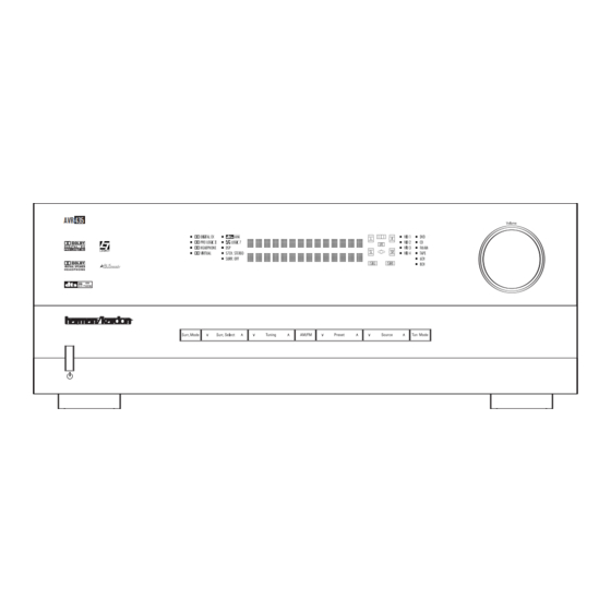
Page 5: Front-Panel Controls
NOTE: To make it easier to follow the instructions that refer to this illustration, a larger copy may be downloaded from the Product Support section for this product at www.harmankardon.com. The following controls and indicators are available on the AVR 435’s front panel: 1 Standby/On Switch... - Page 6 ) Volume Control: Turn this knob clockwise to increase the volume, counterclockwise to decrease the volume. If the AVR 435 is muted, adjusting the volume control will automatically release the unit from the silenced condition.
- Page 7 NOTE: This switch is normally left in the “ON” position. B Headphone Jack: This jack may be used to lis- ten to the AVR 435’s output through a pair of head- phones. Be certain that the headphones have a stan- dard 1/4"...
-
Page 8: Rear-Panel Connections
REAR-PANEL CONNECTIONS REAR-PANEL CONNECTIONS ¡ AM Antenna ™ FM Antenna £ Preamp Outputs ¢ Subwoofer Output ∞ A-BUS Connector § Surround Speaker Outputs ¶ Front Speaker Outputs • Fan Vents ª Center Speaker Outputs ‚ Surround Back/Multiroom Speaker Outputs ⁄ AC Power Cord ¤... - Page 9 (white for front left and red for front right) (+) terminals on the AVR 435 to the red (+) terminals on the speakers and the black (–) terminals on the AVR 435 to the black (–) terminals on the speakers.
- Page 10 REAR-PANEL CONNECTIONS g Remote IR Input: If the AVR 435’s front-panel IR sensor is blocked due to cabinet doors or other obstructions, an external IR sensor may be used. Connect the output of the sensor to this jack. h Remote IR Output: This connection permits the IR sensor in the receiver to serve other remote con- trolled devices.
-
Page 11: Main Remote Control Functions
Lens NOTES: • The function names shown here are each button’s feature when used with the AVR 435. Most buttons have additional functions when used with other devices. When a button is pressed, the function name will appear in the bottom line of the LCD Information Display c. - Page 12 52. AVR Selector: Pressing this button will switch the remote so that it will operate the AVR 435’s functions. If the AVR 435 is in the Standby mode, it will also turn the AVR 435 on. MAIN REMOTE CONTROL FUNCTIONS...
- Page 13 Transport Fast-Play/Scan Buttons: These but- tons have no direct function on the AVR 435, but they are used when the remote is programmed for a com- patible DVD, CD or tape player. Pressing these buttons will transmit a fast-play forward, fast-play reverse, or fast- forward or -reverse scan command, according to the capabilities of the player being controlled.
- Page 14 Lens: The infrared emitters behind the plastic lens at the top of the remote communicate the remote codes to the AVR 435. Be certain that the lens is not covered when using the remote, and point the lens toward the AVR for best results. In learning mode, the remote receives IR codes to be learned through a sensor behind the lens.
-
Page 15: Zone Ii Remote Control Functions
A-BUS product that is connected to the AVR 435’s Multiroom IR Input Jack f. When it is used in the same room as the AVR 435, it will control the functions of the AVR 435 or any compatible Harman Kardon products in that room. -
Page 16: Installation And Connections
Optical and Coaxial Digital Audio Inputs 4. Connect the coaxial or optical Digital Audio Outputs ik on the rear panel of the AVR 435 to the match- ing digital input connections on a CD-R or MiniDisc recorder. -
Page 17: System And Power Connections
Audio Outputs j on the AVR 435’s rear panel. Option 2: Connect the Multiroom Audio Outputs j on the AVR 435 to the inputs of an optional stereo power amplifier. Run high-quality speaker wire from the amplifier to the speakers in the remote room. - Page 18 INSTALLATION AND CONNECTIONS optional, external computer, keypad or control system, the AVR 435 is capable of bi-directional communica- tions that enable the external system to control the AVR, and for the AVR to report status and handshake data back to the controller. Use of the RS-232 port for...
-
Page 19: System Configuration
You are now ready to power up the AVR 435 to begin these final adjustments. 1. Make certain that the AC power cord is firmly inserted into the AC Power Cord Jack ‹... -
Page 20: Input Setup
Be certain to follow the (+) and (–) polarity indicators that are in the battery compartment. 5. Turn the AVR 435 on either by pressing the Standby/On Switch 1 on the front panel, or via the remote by pressing the Power On Button b, the AVR Selector e∫... -
Page 21: Audio Setup
In normal use, this feature is turned off, which means that digital sources are processed at their native sample rate. For example, a 48kHz digital source will be processed at 48kHz. However, the AVR 435 allows you to SYSTEM CONFIGURATION SYSTEM CONFIGURATION... -
Page 22: Surround Setup
When the SURR BACK line of the SPEAKER SETUP menu (Figure 6) is set to NONE the AVR 435 will be con- figured for 5.1-channel operation, and only the modes appropriate to a five-speaker system will appear. When... -
Page 23: Using Ezset/Eq
BACK TO MASTER MENU line and press the Set Button q. Using EzSet/EQ The AVR 435 uses Harman Kardon’s EzSet/EQ tech- nology to automatically configure your system to deliver the best possible performance based on your specific... - Page 24 Step 5. At this point you will begin to hear a series of test tones circulate among all the speakers in your system. While this is happening, the AVR 435 is read- ing the signal to determine which speaker positions...
- Page 25 Near Field measurements from the front left, center and right speakers. By taking this separate set of measurements, the AVR 435 is able to complete its view of the room’s sonic signature and apply equalization as needed to correct spikes and dips in the system’s response.
-
Page 26: Manual Setup
However, if you feel that your listening room or system components are best suited to manual entry of these settings, the AVR 435 also allows you to enter or trim any of these traditional system parameters. Even if you do make the settings manually, we recommend that... -
Page 27: Sub Mode
SUB, which is the “on” position. If the front left/right speakers are set to LARGE, three options are available: • If no subwoofer is connected to the AVR 435, Navigation Button o on the press the ‹... -
Page 28: Speaker Crossover Setting
SYSTEM CONFIGURATION SYSTEM CONFIGURATION • If a subwoofer is connected to the AVR 435, you have the option to have the front left/right “main” speakers reproduce bass frequencies at all times, and have the subwoofer operate only when the AVR 435 is being used with a digital source that contains a dedicated low-frequency effects, or LFE soundtrack. -
Page 29: Output Level Adjustment
Output level adjustment is a key part of the configura- tion of any surround sound product. It is particularly important for a digital receiver such as the AVR 435, as correct outputs ensure that you hear soundtracks with the proper directionality and intensity. - Page 30 When you have verified that all speakers are connected to the correct output terminal, turn the AVR 435 back on and return to this menu to resume the channel adjustment procedure. If any speaker con- nections were changed we also recommend that you rerun EzSet/EQ before making any manual calibration adjustments.
- Page 31 Once the settings outlined on the previous pages have been made, the AVR 435 is ready for operation. While there are some additional settings to be made, these are best done after you have had an opportunity to lis- ten to a variety of sources and different kinds of pro- gram material.
-
Page 32: Operation
Turning the AVR 435 On or Off • When using the AVR 435 for the first time, you must press the Main Power Switch A to turn the unit on. This places the unit in a Standby mode, as indicated by the amber illumination surrounding the Standby/On Switch 1 . -
Page 33: Surround Mode Selection
With the AVR 435 you are able to not only play back the origi- nal compatible digital format, but using the processing power of the Texas Instruments DSP processor it is possible to decode the basic digital track for 2.0 or... -
Page 34: Surround Mode Chart
Logic 7 Cinema Exclusive to Harman Kardon for A/V receivers, Logic 7 is an advanced mode that extracts the maximum surround information from either Logic 7 Music surround-encoded programs or conventional stereo material. When your system has been configured for use with Surround Back speakers Logic 7 Enhance (see page 41), you may choose between either 7.1 or 5.1 versions of the Logic 7 modes, while only the 5.1 versions are available when... - Page 35 You may use any LD or CD player equipped with a digital output to play DTS-encoded discs with the AVR 435. All that is required is to connect the player’s output to either an Optical or Coaxial Input or front panel KM.
- Page 36 DVD player (usually with the “Audio Select” button or in a menu screen on the disc) to send a full 5.1 feed to the AVR 435. It is also possible for the type of signal feed to change during the course of a DVD’s playback.
-
Page 37: Tuner Operation
Digital Audio Outputs ikM. Tuner Operation The AVR 435’s tuner is capable of tuning AM, FM and FM Stereo broadcast stations. Stations may be tuned manually, or they may be stored as favorite station pre- sets and recalled from a 30-position memory. -
Page 38: Output Level Trim Adjustment
Repeat the procedure as needed until all channels requiring adjustment have been set. When all adjust- ments have been made and no further adjustments are made for 5 seconds, the AVR 435 will return to normal operation. The output levels may also be adjusted using the on-... -
Page 39: Advanced Features
Turn-On Volume Level As is the case with most audio/video receivers, when the AVR 435 is turned on, it will always return to the volume setting in effect when the unit was turned off. However, you may prefer to always have the AVR 435 turn on at a specific setting, regardless of what was last in use when the unit was turned off. -
Page 40: Full-Osd Time-Out Adjustment
Full-OSD Time-Out Adjustment The FULL OSD menu system is used to simplify the setup and adjustment of the AVR 435 by using a series of on-screen menus. The factory default setting for these menus leaves them on the screen for 20 seconds after a period of inactivity before they disap- pear from the screen (Time-Out). -
Page 41: Multiroom Operation
The AVR 435 is fully equipped to operate as the con- trol center for a complete multiroom system that is capable of sending one source to a second zone in the house while a separate source is listened to in the main room. -
Page 42: Multiroom Operation
Selector Buttons ç∂d to turn on to a specific source. As long as an IR feed to the AVR 435 has been established from the remote room, using any of the buttons on either remote will control the remote loca- tion volume rî, change the tuner frequency... -
Page 43: Configuring The Remote
CD recorders and cassette decks. The codes for other brand devices may be programmed into the AVR 435 remote using its extensive library of remote codes or a head-to-head learning process for codes not in the internal library. -
Page 44: Automatic Code Entry
To teach commands from one product’s remote into the AVR remote: The AVR 435’s remote not only allows you to “learn” in the commands from any compatible remote; it also allows you to learn a separate code into the Input Selector Buttons d. -
Page 45: Learning Codes For An Input Selector
Step 4. Learning Codes for an Input Selector The AVR 435’s remote allows you to learn a specific code to be attached to one of the Input Selectors d so that whenever that button is pressed, you will not only be selecting that device as the AVR’s input... -
Page 46: Changing Devices
However, in some circumstances you may have con- figured your system so that the devices connected to the AVR 435 do not correspond to the default device settings and the legends printed on the remote. For example, if your system has two VCRs you may con- nect the second VCR to the VID 2 input. - Page 47 Following the instructions on the remote’s LCD screen, press the first key you wish to be transmitted in the macro. In our example, we first want the AVR 435 to turn on, so the Power Button should be pressed.
-
Page 48: Punch-Through Configuration
For example, if your TV, cable box or satellite receiver is connected through the AVR 435, you will most likely want to use the AVR 435’s volume control commands even when the remote has been set to issue all other commands for the video device. - Page 49 For example, you may wish to use a cable box or satellite receiver as the source for a VCR, so you would want the Channel Up/Down Buttons...
-
Page 50: Renaming
Note that renaming a device in the remote will not change the name of the input used by the on-screen menu system of the AVR 435. NOTES ON RENAMING DEVICES: • To move the cursor to the right or left of the display ‹... -
Page 51: Resetting The Remote
rename the DSP Surround Mode Selector which is normally not used when DVD is selected, so that it reads ZOOM in the remote’s display. 1. Press and hold the Program Button about three seconds while the message shown in Figure 24 appears in the remote’s LCD Information Display . -
Page 52: Device Priority Timing
Backlight Options The AVR 435’s remote has a built-in backlight system that makes it easier to use the remote when the room lighting is dimmed for an optimal home theater experi- ence. - Page 53 30-second period. The message shown in Figure 90 will appear briefly, and the remote will then exit the feature being programmed and any data entered will be lost. T I M E O U T O R C L R K E Y P R E S S E D Figure 90 •...
-
Page 54: Troubleshooting Guide
• Additional cooling may not be required In addition to the items shown above, additional information on troubleshooting possible problems with your AVR 435, or installation-related issues, may be found in the list of “Frequently Asked Questions” which is located in the Product Support section of our Web site at www.harmankardon.com. -
Page 55: Technical Specifications
IF Rejection 90dB Supplied Accessories The following accessory items are supplied with the AVR 435. If any of these items are missing, please contact Harman Kardon customer service at www.harmankardon.com. • A system remote control • An AM loop antenna •... -
Page 56: Index
Full-OSD Time-Out 40 Hall Mode 23, 34 Headphones 7, 33 Input Setup 20–22 Installation 16–18 Installation Location 4 IR Receiver 6, 17 Logic 7 23, 34 Manual Mode Tuning 6, 12–13, 37 INDEX INDEX Manual System Setup 26–31 Master Menu 20 Memory Backup 38 MP3 36–37... - Page 57 NOTES NOTES NOTES...
- Page 58 NOTES NOTES...
- Page 59 NOTES NOTES NOTES...
- Page 60 250 Crossways Park Drive, Woodbury, New York 11797 www.harmankardon.com © 2005 Harman International Industries, Incorporated ® Part No. ZKD1101HA00-3...
Need help?
Do you have a question about the AVR 435 and is the answer not in the manual?
Questions and answers