Harman Kardon AVR 240 Owner's Manual
Harman kardon avr 240: owners guide
Hide thumbs
Also See for AVR 240:
- Service manual (156 pages) ,
- Owner's manual (60 pages) ,
- Quick start manual (4 pages)
Table of Contents

Related Manuals for Harman Kardon AVR 240


Summary of Contents for Harman Kardon AVR 240
- Page 1 Power for the Digital Revolution AVR 240 AUDIO/VIDEO RECEIVER OWNER’S MANUAL DIGITAL LOGIC 7 PRO LOGIC 3 STEREO HEADPHONE 5 7 CH. STEREO SURR. OFF ® ® VID 1 VID 2 VID 3 FMAM VID 4 TAPE 6 8 CH...
-
Page 2: Table Of Contents
– (number in an oval) indicates a button or indicator on the remote The appearance of the text or cursor for your receiver’s on-screen menus may vary slightly from the illustrations in this manual. Whether the text appears in all uppercase or upper- and lowercase characters, performance and operation remain the same. -
Page 3: Introduction
AVR 240 accomplishes its mission by har- nessing advanced technologies usually found only in higher-priced receivers. The AVR 240 has been engineered so that it is easy to take advantage of all the power of its digital tech- nology. However, to obtain the maximum enjoyment from your new receiver, we urge you to read this manual. -
Page 4: Important Safety Information
Do not obstruct the ventilation slots on the top of the unit, or place objects directly over them. Due to the weight of the AVR 240 and the heat generated by the amplifiers, there is the remote possibility that the rubber padding on the bottom of the unit’s feet may leave marks on certain... -
Page 5: Digital Logic
3 Standby/On Switch: When the Main Power Switch 1 is “ON, ” press this button to turn on the AVR 240; press it again to turn the unit off. The Power Indicator 2 turns blue when the unit is on. - Page 6 @ Set Button: When making choices during the setup and configuration process, press this button to enter the desired setting into the AVR 240’s memory. # Digital Input Selector: Press this button to select one of the digital audio inputs or the analog audio input for any source.
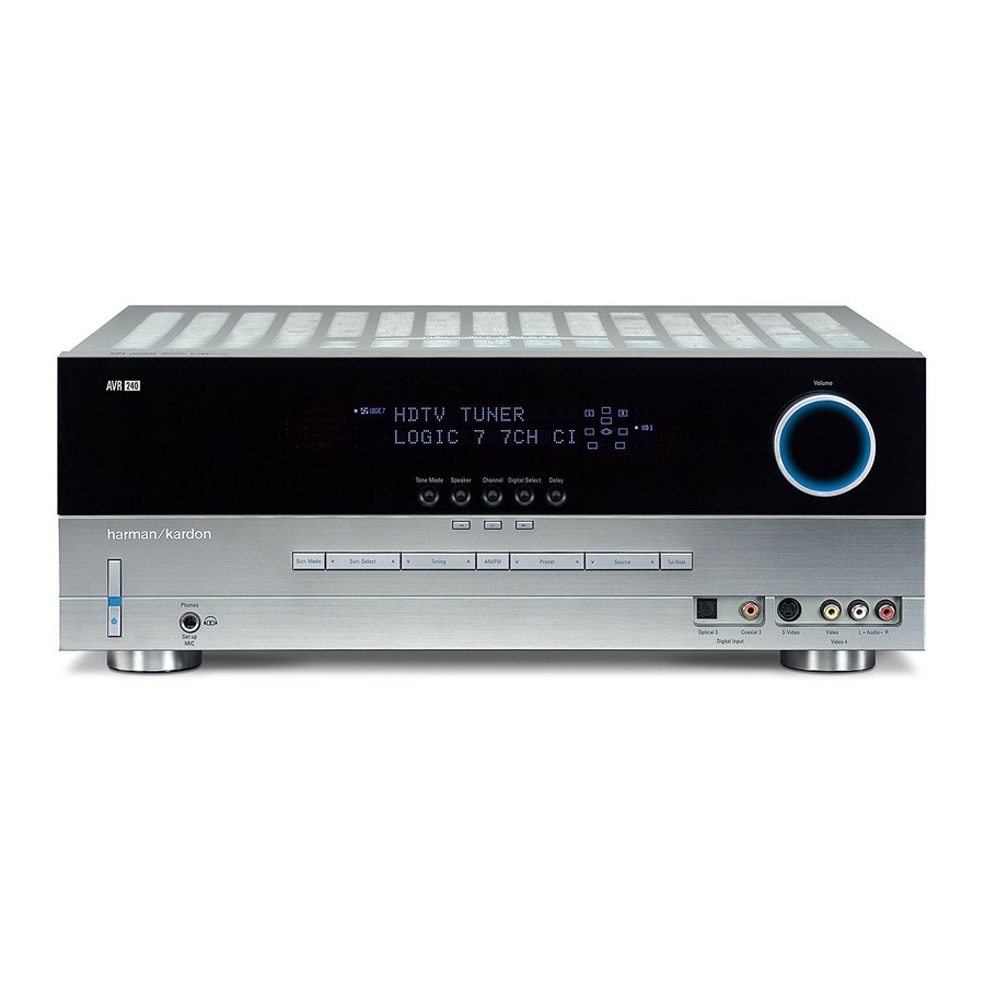
- Page 7 FRONT-PANEL CONTROLS Ù Upper Display Line: Depending on the unit’s sta- tus, a variety of messages will appear here. In normal operation, this line will show current input source and which analog or digital input is in use. When the tuner is the input, this line will identify the station as AM or FM and show the frequency and preset number, if any.
-
Page 8: Rear-Panel Connections
Component Video “Y”: Green Component Video “Pr”: Red Component Video “Pb”: Blue ∞ Remote IR Input: If the AVR 240’s front-panel IR sensor is blocked due to cabinet doors or other obstructions, an external IR sensor may be used. Connect the output of the sensor to this jack. - Page 9 (white for front left and red for front right) (+) terminals on the AVR 240 to the red (+) terminals on the speakers and the black (–) terminals on the AVR 240 to the black (–) terminals on the speakers.
- Page 10 NOTE ON VIDEO CONNECTIONS: When connecting a video source product such as a VCR, DVD player, satellite receiver, cable set-top box, personal video recorder or video game to the AVR 240, you may use either a composite or S-video connection, but not both.
-
Page 11: Remote Control Functions
6-Channel/8-Channel Direct Input Mute NOTES: • The function names shown here are each button’s feature when used with the AVR 240. Most buttons have additional functions when used with other devices. See pages 47–48 for a list of these functions. - Page 12 AVR Selector: Pressing this button will switch the remote so that it will operate the AVR 240’s functions. If the AVR 240 is in the Standby mode, it will also turn the AVR 240 on. g AM/FM Tuner Select: Press this button to select the AVR 240’s tuner as the listening choice.
- Page 13 Disc Skip Button: This button has no direct function for the AVR 240 but is most often used to change to the next disc in a CD or DVD player when the remote is programmed for that type of device.
- Page 14 Bridge , pressing this selector will select the iPod as the audio source input device for the AVR 240. In addition, if a video display is connected to one of the Video Monitor Outputs c , the iPod’s messages will appear on screen, and in the Upper and Lower Display Lines PQ.
-
Page 15: Installation And Connections
4. Connect the Coaxial or Optical Digital Audio Outputs ·a on the rear panel of the AVR 240 to the matching digital input connections on a CD-R or MiniDisc or other digital recorder. -
Page 16: System And Power Connections
• When connecting a video source to the AVR 240, you may use either composite, component or S-video, but only one type of video may be connected for each device. - Page 17 The Unswitched AC Accessory Outlet ° will receive power as long as the unit is plugged into a powered AC outlet. Once the AC Power Cord fl is connected, you are almost ready to enjoy the AVR 240’s incredible power and fidelity! INSTALLATION AND CONNECTIONS...
-
Page 18: System Configuration
SYSTEM CONFIGURATION When all audio, video and system connections have been made, the final steps before listening to your new AVR are to make the configuration adjustments that tailor the unit to the other components in your system as well as to accommodate your personal listening preferences. - Page 19 NOTE: The 6.1-channel configuration is not recom- mended for the AVR 240. We strongly recommend a 7.1-channel installation as described below. When 6.1-channel materials are played through a 7.1-chan-...
-
Page 20: System Setup
You are now ready to power up the AVR 240 to begin these final adjustments. 1. Make certain that the AC Power Cord fl is firmly inserted into an unswitched AC outlet. -
Page 21: Input Setup
37–38, you may select from a limited number of other surround modes for these materials. If you wish to have the AVR 240 default to one of these alternate surround modes each time a Dolby Digital or DTS SYSTEM CONFIGURATION... -
Page 22: Audio Setup
Buttons o until the word YES appears if you wish charging to continue, and the blue lighting on The Bridge will remain lit when the AVR 240 is in Standby mode to indicate that charging is taking place. The default setting is NO, in which the docked... - Page 23 When the SURR BACK line of the SPEAKER SIZE submenu (Figure 12 on page 27) is set to NONE, the AVR 240 will be configured for 5.1-channel operation, and only the modes appro- priate to a five-speaker system will appear. When the...
-
Page 24: Automated Speaker Setup Using Ezset
Set Button p. Automated Speaker Setup Using EzSet+ The AVR 240 is one of the first receivers in its class to offer automated speaker setup and system calibration. This process greatly simplifies the installation of your... - Page 25 Step 3: Plug the EzSet+ microphone into the AVR 240’s Headphone Jack 4, making certain that the mini-plug to 1/4" phone plug adaptor sup- plied with the microphone is firmly connected. The...
-
Page 26: Manual Setup
Basic Operation section of this manual on page 32 to learn how to operate the AVR 240, although we recommend that you first record your system’s settings using the work- sheet on page 62 in case the settings need to be reentered due to a power loss or for some other rea- son. -
Page 27: Speaker Size
The surround back speakers need only be configured to be active once, and the AVR 240 will set them as active for all surround modes and sources. If you wish to set them as inactive for some sources, you may scroll down to the BASS MGR line of the SPEAKER SIZE menu and press the ‹/›... -
Page 28: Speaker Crossover Settings
SUB, which is the “on” position. If the front left/right speakers are set to LARGE, three options are available: • If no subwoofer is connected to the AVR 240, Buttons o on the remote so press the ‹... -
Page 29: Delay Settings
In addition to adjusting the delay time for each individ- ual speaker position, the AVR 240 allows you to adjust the delay for the combined output of all speakers as a group. This feature is called A/V Sync Delay; it allows... -
Page 30: Output Level Adjustment
• If you have elected to use your AVR 240 in a 6.1- channel configuration, you will not be able to use the EzSet+ procedure unless you follow these instructions. - Page 31 AVR. Once the settings outlined on the previous pages have been made, the AVR 240 is ready for operation. While there are some additional settings to be made, these are best done after you have had an opportunity to lis- ten to a variety of sources and different kinds of pro- gram material.
-
Page 32: Operation
Turning the AVR 240 On or Off • When using the AVR 240 for the first time, you must first press the Main Power Switch 1 on the front panel to turn the unit on. This places the unit in a Standby mode, as indicated by the amber color of the Power Indicator 2 . -
Page 33: Surround Mode Selection
Dolby Headphone modes and select the one that you prefer. Surround Mode Selection One of the important features of the AVR 240 is its ability to reproduce a full multichannel surround sound field from digital sources, analog matrix surround- encoded programs and standard stereo programs. -
Page 34: Surround Mode Chart
Dolby Digital EX reproduces specially encoded soundtracks so that a full 6.1/7.1 sound field is available. When the receiver is set for 6.1/7.1 operation and a Dolby Digital signal is present, the EX mode is automatically selected. - Page 35 Dolby Virtual Speaker Dolby Virtual Speaker uses advanced technology to simulate the sonic signature of a speaker location even when there is no speaker physically Reference present in that location. The Reference (“REF”) mode activates any missing speakers to simulate a 5.1 presentation with accurate localization. Wide The Wide mode virtualizes the locations of the front-channel speakers to create a wider image and a more enveloping sound field.
-
Page 36: Digital Audio Playback
(HDTV) system. An optional, external RF demodulator is required to use the AVR 240 to listen to the Dolby Digital sound- tracks available on laser discs. Connect the RF output of the LD player to the demodulator and then connect the digital output of the demodulator to the Optical or Coaxial Inputs *(bg of the AVR 240. -
Page 37: Surround Mode Post Processing
DVD player (usually with the “Audio Select” button or in a menu screen on the disc) to send a full 5.1 feed to the AVR 240. It is also possible for the type of signal feed to change during the course of a DVD playback. -
Page 38: Surround Mode Availability
OPERATION Surround Mode Availability for Incoming Bitstreams and Audio Signals For incoming Dolby Digital signals, the following modes are available: Incoming Bitstream Available Surround Modes Dolby Digital 1/0/.0 or 1/0/.1 Dolby Digital, Dolby Digital Stereo, Dolby Virtual Speaker Reference (2 Speaker), Dolby Virtual Speaker Wide (2 Speaker), VMAx (N or F) Dolby Digital 2/0/.0 or 2/0/.1 Dolby Pro Logic II (Movie, Music or Game), Dolby Pro Logic, Dolby Digital, Dolby Virtual Speaker Reference (2 or 3 Speaker), Dolby Virtual Speaker Wide (2, 3, 4 or 5 Speaker), Dolby Pro Logic IIx** (Movie, Music or Game), VMAx (N or F) -
Page 39: Tuner Operation
. However, the digital signals will be passed through to the Digital Audio Outputs ·a. Tuner Operation The AVR 240’s tuner is capable of tuning AM, FM and FM Stereo broadcast stations. Stations may be tuned manually, or they may be stored as favorite station presets and recalled from a 30-position memory. -
Page 40: Using
Repeat the procedure as needed until all channels requiring adjustment have been set. When all adjust- ments have been made and no further adjustments are made for five seconds, the AVR 240 will return to normal operation. The channel output for any input may also be adjusted using the full-OSD on-screen menu system. - Page 41 OPERATION after the AVR is turned off and then on again. To return the displays to full brightness without turning the unit off, press the Dim Button as needed until the displays are on. In addition to lowering the brightness of the displays or turning them off completely, you may wish to have them appear whenever a button on the remote or front panel is pushed, and then gradually fade out after...
-
Page 42: Advanced Features
Turn-On Volume Level As is the case with most audio/video receivers, when the AVR 240 is turned on, it will always return to the volume setting in effect when the unit was turned off. However, you may prefer to always have the AVR 240 turn on at a specific setting, regardless of what was last in use when the unit was turned off. - Page 43 AVR for and the format of the incoming bitstream. The AVR 240 allows you to set the unit so that it will either use the default mode or switch to your desired mode.
-
Page 44: Programming The Remote
002 in Step 4. Auto Search Method If the unit you wish to include in the AVR 240’s remote is not listed in the code tables in this manual or if the code does not seem to operate properly, you may wish... -
Page 45: Programmed Device Functions
Function List and then look in the column for the device you are controlling. For example, button number 46 is the Direct button for the AVR 240, but it is the “Favorite” button for many cable television boxes and satellite receivers. Button number 32 is the Delay button for the AVR 240, but the Open/Close button for CD players. -
Page 46: Volume Punch-Through
TV viewing, you may wish to have the AVR 240’s volume activated, although the remote is set to run the TV. Either the AVR 240 or TV volume control may be associated with any of the remote’s devices. -
Page 47: Function List
Button Name AVR Function Power On Power On Power On Power Off Power Off Power Off Mute Mute Mute AVR Select AVR Select DVD Input Select DVD Select CD Input Select CD Select Tape Tape Input Select Tape Select VID 1 (VCR) Video 1 Select VCR Select VID 2 (CBL/SAT) Video 2 Select... - Page 48 FUNCTION LIST Button Name AVR Function Tuning Up Tuning Up Next Chapter Direct Direct Tuner Entry Angle Clear Clear Clear Preset Up Preset Tune Up Slow Forward Tuning Down Tuning Down Prev Chapter D. Skip Disc Skip (DVD) Disc Skip Preset Down Preset Tune Down Slow Rev...
-
Page 49: Setup Code Tables
CONCERTO CONTEC CORANDO CORONADO CRAIG CROWN CURTIS MATHES DAEWOO DAYTRON DIGI LINK DYNASTY DYNATECH ELECTROHOME EMERSON FUNAI FUTURETECH GOLDSTAR/LG GRUNDIG HALL MARK HARMAN KARDON HITACHI INFINITY INKEL JC PENNEY JENSEN KAWASHO KENWOOD LLOYTRON LODGENET SETUP CODE TABLE: TV SETUP CODES... - Page 50 SETUP CODE TABLE: TV Manufacturer/Brand Setup Code Number LOGIK LUXMAN MAGNAVOX MARANTZ MATSUI MEMOREX METZ MINERVA MITSUBISHI NATIONAL NIKEI ONKING ONWA OPTONICA ORION PANASONIC PHILCO PHILIPS PIONEER PORTLAND PROSCAN PROTON QUASAR RADIO SHACK REALISTIC RUNCO SAMPO SAMSUNG SANYO SCOTT SEARS SHARP SIEMENS SIGNATURE...
- Page 51 Manufacturer/Brand Setup Code Number TEKNIKA TELERENT TERA THOMSON TOSHIBA TOTEVISION VIDEO CONCEPTS VIDTECH WARDS YAMAHA YORK YUPITERU ZENITH ZONDA SETUP CODE TABLE: TV SETUP CODES...
- Page 52 DAYTRON 018 048 DYNATECH EMERSON 013 040 042 110 112 FISHER FUNAI 076 095 124 GO VIDEO GOLDSTAR/LG 018 107 HARMAN KARDON 018 049 HITACHI 040 048 JC PENNEY 018 045 JENSEN 018 048 111 132 KENWOOD 020 048 LLOYD...
- Page 53 Manufacturer/Brand Setup Code Number REALISTIC 017 020 040 045 159 SALORA SAMSUNG 045 051 095 105 109 SANSUI 048 116 147 SANYO 017 020 SCOTT 110 112 SEARS 017 020 SHARP 129 156 SONY 080 129 SOUNDESIGN SYLVANIA SYMPHONIC TANDY 017 040 TASHICO TATUNG...
- Page 54 AKAI AUDIO TECHNICA AUDIOACCESS AUDIOFILE CALIFORNIA AUDIO CAPETRONIC CARRERA CARVER CASIO CLARINETTE DENON EMERSON FISHER FRABA FUNAI GENEXXA GOLDSTAR/LG HAITAI HARMAN KARDON HITACHI INKEL JC PENNEY JENSEN KENWOOD LOTTE LUXMAN MAGNAVOX MARANTZ MCINTOSH MITSUMI MODULAIRE NAKAMICHI NIKKO ONKYO OPTIMUS PANASONIC...
- Page 55 YAMAHA YORK SETUP CODE TABLE: DVD Manufacturer/Brand Setup Code Number APEX DIGITAL DENON 019 051 003 004 GOLDSTAR/LG 005 055 064 066 HARMAN KARDON 001 002 MAGNAVOX MARANTZ MITSUBISHI ONKYO 009 048 PANASONIC 024 030 044 PHILIPS PIONEER 041 065...
- Page 56 SETUP CODE TABLE: SAT Manufacturer/Brand Setup Code Number ALPHASTAR ALPHASTAR DBS ALPHASTAR DSR BIRDVIEW CHANNEL MASTER 320 321 CHAPARRAL 315 316 CITOH DRAKE 313 317 413 481 DX ANTENNA 331 352 ECHOSTAR 395 397 453 463 ELECTRO HOME FUJITSU 324 329 GENERAL INSTRUMENT 303 311 365 403...
- Page 57 Manufacturer/Brand Setup Code Number HARMAN KARDON SETUP CODE TABLE: CBL Manufacturer/Brand Setup Code Number 001 011 ALLEGRO AMERICAST ARCHER BELCOR CABLE STAR 033 113 CITIZEN COLOUR VOICE 085 090 DIGI EAGLE EASTERN 066 070 ELECTRICORD EMERSON FOCUS G.I. 001 011 017 096 097...
- Page 58 SETUP CODE TABLE: CBL Manufacturer/Brand Setup Code Number REMBRANT SAMSUNG 003 072 186 SCIENTIFIC ATLANTA 183 203 221 222 SEAM SIGNATURE 001 188 SPRUCER 053 081 177 189 STARCOM 002 011 163 STARGATE TANDY TELECAPATION TEXSCAN TIMELESS TOCOM 170 205 UNITED CABLE UNIVERSAL 033 034 039 042 113...
-
Page 59: Troubleshooting Guide
In addition to the items shown above, additional information on troubleshooting possible problems with your AVR 240, or installation-related issues, may be found in the list of “Frequently Asked Questions” which is located in the Product Support section of our Web site at www.harmankardon.com. -
Page 60: Technical Specifications
IF Rejection 90dB Supplied Accessories The following accessory items are supplied with the AVR 240. If any of these items are missing, please contact Harman Kardon customer service at www.harmankardon.com. • A system remote control • An AM loop antenna •... -
Page 61: Trademark Acknowledgements
® 3, 13, 14, 15, 40 IR Receiver (Remote Sensor) 5, 7, 16 Logic 7 3, 6, 11, 13, 19, 21, 22, 23, 24, 27, 28, 29, 31, 33, 34, 36, 38, 39, 43, 48, 60 Macros 13, 44 Manual Mode Tuning 6, 12–13, 39... -
Page 62: Appendix - Settings Worksheet
APPENDIX – SETTINGS WORKSHEET Table 1: Input Settings FEATURE VIDEO 1 Input Title Component Video Input Component Component Video 1 (Y/N) Video 2 (Y/N) Video 2 (Y/N) Digital Audio Input Auto Poll (On/Off) Surround Mode Night Mode Front L/R Speaker Size †... - Page 64 ® 250 Crossways Park Drive, Woodbury, New York 11797 Power for the Digital Revolution ® www.harmankardon.com © 2006 Harman International Industries, Incorporated. All rights reserved. Part No. CQX1A1026Z 4/06...