Sign In
Upload
Download
Add to my manuals
Delete from my manuals
Share
URL of this page:
HTML Link:
Bookmark this page
Add
Manual will be automatically added to "My Manuals"
Print this page
×
Bookmark added
×
Added to my manuals
Manuals
Brands
AEA Manuals
Amplifier
500 Series
Owner's manual
AEA 500 Series Owner's Manual
Hide thumbs
1
2
Table Of Contents
3
4
5
6
7
8
9
10
11
12
page
of
12
Go
/
12
Contents
Table of Contents
Bookmarks
Advertisement
Quick Links
Download this manual
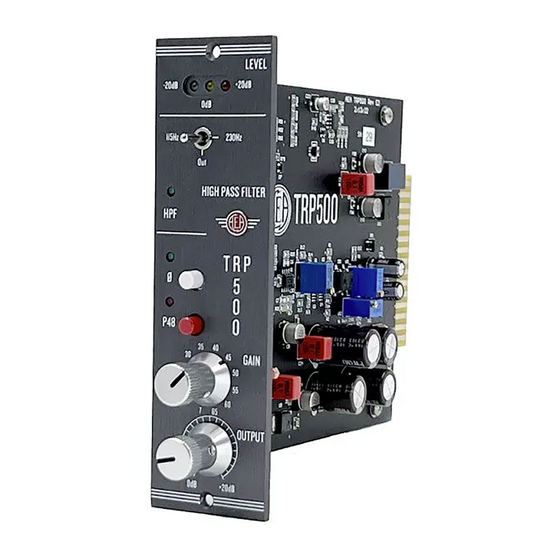
AEA TRP500
OWNER'S MANUAL
500 SERIES MICROPHONE PREAMPLIFIER
Table of
Contents
Previous
Page
Next
Page
1
2
3
4
5
Advertisement
Need help?
Do you have a question about the 500 Series and is the answer not in the manual?
Ask a question
Questions and answers
Related Manuals for AEA 500 Series
Amplifier AEA AEA RPQ500 Owner's Manual
High performance preamp (16 pages)
Amplifier AEA LA-30 Operating Manual
Hf (17 pages)
Amplifier AEA rpq500 Owner's Manual
Versatile mic preamp in the 500 series format (16 pages)
Amplifier AEA RPQ3 Owner's Manual
2-channel ribbon preamp with eq (16 pages)
Amplifier AEA TRP2 Owner's Manual
The original 2-channel ribbon preamp (12 pages)
Amplifier AEA TRP3 Owner's Manual
The original 2-channel ribbon preamp (12 pages)
Amplifier AEA RPQ2 Owner's Manual
(20 pages)
This manual is also suitable for:
Trp500
Print
Rename the bookmark
Delete bookmark?
Delete from my manuals?
Login
Sign In
OR
Sign in with Facebook
Sign in with Google
Upload manual
Upload from disk
Upload from URL


Need help?
Do you have a question about the 500 Series and is the answer not in the manual?
Questions and answers