Table of Contents
Advertisement
Quick Links
Advertisement
Table of Contents
Troubleshooting

Related Manuals for DKK-TOA MBM-162

Summary of Contents for DKK-TOA MBM-162
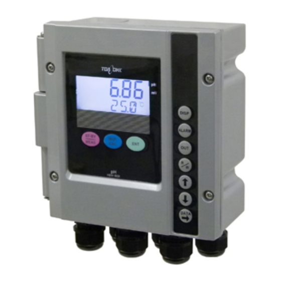
- Page 1 ELECTRODELESS CONCENTRATION ANALYZER MODEL MBM-162 Please keep this instruction manual close at hand of the persons who are in charge of the operation of this product. Before operating this product, please read this instruction manual carefully for its correct handling.
- Page 2 Introduction Introduction (a) Thank you for your purchase of our product. The Model: MBM-162 Electrodeless Conentration Analyzer (hereafter called the analyzer or the product) is an indicating analyzer in a measurement system that measures the electrical conductivity of a solution continuously and converts the measured value into concentration and displays/outputs it.
- Page 3 Model: MBM-162 Introduction • Any problem of the product such as deterioration or damage of the detecting section or inappropriate insulation of cables. • Improper setting of operating conditions or calibration operation. • Electrical interference such as noise in the vicinity or improper grounding.
-
Page 4: Safety Information
Model: MBM-162 Safety Information Safety Information (1) Meaning of markings Meaning of symbols such as the ones used in notations of warning in the instruction manual is described below. In addition, the alert symbol ( : General caution symbol) used on a product label, etc. -
Page 5: Notes On Use Of The Instruction Manual
(d) The contents of the manual may be changed without prior notice for reasons such as to improve performance. (e) Intellectual property right of the manual belongs to DKK-TOA. All or part of the manual must not be reproduced without permission. -
Page 6: Product Warranty
(h) Loss of data, settings, programs, or software stored on the product not attributable to DKK-TOA. (i) Any product other than DKK-TOA’s, if specified by the purchaser or user, that incorporates, or is incorporated into or combined with DKK-TOA’s products (*1). -
Page 7: Reading Guide
Model: MBM-162 Reading Guide Reading Guide Refer to the necessary sections of this instruction manual depending on your purposes such as understanding the outline of this product or starting the product as shown below. The numbers in circles indicate sections to be referred to in sequential order. -
Page 8: Table Of Contents
Model: MBM-162 Table of Contents Table of Contents ●Introduction ················································································································1 ●Safety Information ·······························································································3 (1) Meaning of markings ⋅⋅⋅⋅ 3 (2) Safety compliance items ⋅⋅⋅⋅ 3 (3) Notes on use of the instruction manual ⋅⋅⋅⋅ 4 ●Product Warranty ·································································································5 ●Reading Guide ·······································································································6... - Page 9 Model: MBM-162 Table of Contents (1) Adjustment of concentration transmission output ⋅⋅⋅⋅ 42 (2) Adjustment of temperature transmission output ⋅⋅⋅⋅ 43 4. Maintenance ·······································································································44 4.1 Maintenance List ····································································································44 4.2 Washing the Sensor·······························································································45 4.3 Inspection of Temperature Element ······································································46 4.4 Adjustment Using a Solution of Known Concentration ········································48 5.
- Page 10 Model: MBM-162 Table of Contents (2) Examples of sensor installation ⋅⋅⋅⋅71 (3) Adjustment of proper cell constant when shielding exists ⋅⋅⋅⋅ 72 8.3 Wire Connection·····································································································73 (1) Connection diagram ⋅⋅⋅⋅ 73 (2) Cable ports ⋅⋅⋅⋅ 74 (3) External input/output terminals ⋅⋅⋅⋅ 75 (4) Sensor cable input terminals ⋅⋅⋅⋅...
-
Page 11: Control Panel Functions
Model: MBM-162 1. Control Panel Functions 1. Control Panel Functions (1) Names of main components Control panel DISP key Display panel ALARM key OUT key STAND-BY key Range key Up key Down key DATA key Enter key Names of Main Components... -
Page 12: Functions Of Keys And Indictors
Model: MBM-162 1. Control Panel Functions (2) Functions of keys and indictors Functions of Keys Operation key Function (notation in the text) • Pressing this key longer (3 seconds or more) in the measurement mode Stand-by key changes the screen to the “Setting Mode Concentration Measured Value”... - Page 13 Model: MBM-162 1. Control Panel Functions (Continued from previous page) Operation key Function (notation in the text) • Pressing this key in the measured value screen group causes the screen to go DATA key to the concentration conversion data, etc. display screen group. If this key is pressed repeatedly, the screen switches to another one in the group and finally returns to the “Concentration Measured Value”...
-
Page 14: Main Sensors
Model: MBM-162 1. Control Panel Functions (Continued from previous page) Functions of indictors Function • Indicates that the screen is related to the alarm output. ALARM indictor ALARM1 • ALARM1 indicates that Alarm 1 has occurred and ALARM2 indicates that Alarm 2 has occurred. - Page 15 Model: MBM-162 1. Control Panel Functions Screw-in method Flange method Model ME-11T-1-O Model ME-11T-1-D Sensor with case Model ME-11T-1-H ME-11T Series Sensors (Reference cell constant: 2.60/cm) - 14 -...
-
Page 16: Operation
Model: MBM-162 2.1 Operation Start Procedure 2. Operation 2.1 Operation Start Procedure Operate the analyzer in the procedure below. The measuring system including the analyzer becomes ready to operate in normal operating conditions. ① Check the installation. ⋅⋅⋅⋅⋅⋅ Check that the necessary installation work described in 7. - Page 17 Model: MBM-162 2.1 Operation Start Procedure Example of Concentration Measured Value Screen ⑤ Go to the transmission output range, etc. display screen group. ⋅⋅⋅⋅⋅⋅ Press while a screen of the measured value screen group is displayed. • The “Concentration Transmission 4mA Value Display (4mA)” screen of the transmission range, etc.
- Page 18 Model: MBM-162 2.1 Operation Start Procedure ⑧ Return to “Concentration Measured Value” screen. ⋅⋅⋅⋅⋅⋅ Press ⑨ Check other setting values. ⋅⋅⋅⋅⋅⋅ Check other setting values shown in the table below and change them, if necessary. Among them, “Concentration Transmission 4mA Value display (4mA)” screen, “Concentration Transmission 20mA Value Display (20mA)”...
-
Page 19: Stopping The Operation
Model: MBM-162 2.2 Stopping the Operation • Concentration and Temperature Measured Value Screen • Compensation and Conductivity Screen ⑪ Enable the key lock function ⋅⋅⋅⋅⋅⋅ It is recommended to enable the key lock function in advance to prevent the setting values from being changed by mistake during setting. Pressing together longer (3 seconds or more) switches this function on and off (valid/invalid). -
Page 20: Modes Of Operations
Model: MBM-162 Modes and Operation Screen Map 3. Modes of Operations 3.1 Modes and Operation Screen Map (1) Mode Switching (a) The screens to check or perform settings are separated into 3 modes as shown below. Measurement mode Setting mode... - Page 21 Model: MBM-162 Modes and Operation Screen Map (g) If a specified key is pressed (such as ), that corresponds to each group in the measurement mode or in the setting mode, the screen goes to that group. 3.1(2) “Operation screen map”...
-
Page 22: Operation Screen Map
Model: MBM-162 Modes and Operation Screen Map (2) Operation screen map Power on (ON) [ Measurement mode ] Alarm display screen group Measured value screen group (To switch screen: (To switch screen: Alarm 1 Set Point Display (L/H/OFF) Screen Concentration Measured Value Screen Alarm 1 Delay Time Display (DLY.T) Screen... - Page 23 Model: MBM-162 Modes and Operation Screen Map Compensation screen group Setting Mode Concentration Measured Value Screen (To switch screen: Press longer Concentration Compensation On/Off Screen Concentration Compensation Method (SHFT/SPAN) Screen Temperature Compensated Value (SHFT/SPAN) Screen Temperature Shift On/Off (SHFT) Screen...
-
Page 24: Measurement Mode Operation
Model: MBM-162 Measurement Mode Operation 3.2 Measurement Mode Operation (1) Measured value screen selection (a) The screens shown in the table below are provided in the measured value screen group. The current concentration measured value or the temperature measured value can be checked. These screens are used in normal measurement state. -
Page 25: Checking The Alarm
Model: MBM-162 Measurement Mode Operation (Continued from previous page) Name Screen example Description • Main display ⋅⋅⋅⋅ The current ③ ◎ Temperature Measured Value 26.3 Screen temperature measured value (°C). mS/cm • Sub display ⋅⋅⋅⋅ Shift value is °C displayed when “on” is set to the “Temperature Shift On/Off (SHFT)”... - Page 26 Model: MBM-162 Measurement Mode Operation Sequence and Contents of Alarm Display Screen Group Name Screen example Description (To switch screen: • Main display ⋅⋅⋅⋅ The set point ① ◎ Alarm 1 Set Point Display Screen (concentration value) of Alarm 1 high/low alarm value (%).
-
Page 27: Checking The Transmission Output Range And Hold Setting
Model: MBM-162 Measurement Mode Operation (3) Checking the transmission output range and hold setting (a) The screens shown in the table below are provided in the transmission range, etc. display screen group. The concentration and the temperature transmission output range correspond to the 4 to 20mADC. -
Page 28: Checking The Proper Cell Constant
Model: MBM-162 Measurement Mode Operation (Continued from previous page) Name Screen example Description • Main display ⋅⋅⋅⋅ The symbol indicting ⑤ ◎ Hold Display Screen HoLd the “Hold” type set in the setting mode. mS/cm S.OUT HoLd (Hold) ⋅⋅⋅⋅ Outputs the transmission output immediately <When Hold is set>... -
Page 29: Checking The Concentration Conversion Data
Model: MBM-162 Measurement Mode Operation Sequence and Contents of Proper Cell Constant, etc. Display Screen Group Name Screen example Description (To switch screen: • Main display ⋅⋅⋅⋅ Displays the set ① ◎ Proper Cell Constant Display 2.62 Screen proper cell constant, a value of approx. - Page 30 Model: MBM-162 Measurement Mode Operation Symbol Representing Each Conductivity of the Concentration Conversion Data Concentration (%) X1T1 X2T1 X3T1 X4T1 X5T1 X6T1 X1T2 X2T2 X3T2 X4T2 X5T2 X6T2 X1T3 X2T3 X3T3 X4T3 X5T3 X6T3 X1T4 X2T4 X3T4 X4T4 X5T4 X6T4...
-
Page 31: Setting Mode Operation
Model: MBM-162 3.3 Setting Mode Operation 3.3 Setting Mode Operation (1) Changing the concentration compensation (a) It is possible to change the current on/off setting of the concentration compensation function, the compensation method and the value after compensation. The concentration compensation function is set to “oFF”... -
Page 32: Changing The Temperature Shift
Model: MBM-162 3.3 Setting Mode Operation (Continued from previous page) Procedure and screen example Operation ⑤ Set a concentration compensation method. to display your desired choice on the sub ················ (If you select “oFF” in ④, this screen does not display and press appear.) -
Page 33: Changing The Alarm Setting
Model: MBM-162 3.3 Setting Mode Operation (Continued from previous page) Procedure and screen example Operation ③ Select the “Temperature Shift On/Off” screen. Press longer to enter the compensation screen ········ group. • Pressing repeatedly until the sub display shows “SHIFT” and the temperature indication becomes ST-BY “°C”... - Page 34 Model: MBM-162 3.3 Setting Mode Operation 【IMPORTANT】 • For 2 minutes after power is turned on, the alarm output does not turn on (close). If a delay time is set, time for this delay time will be added further. Alarm delay time...
- Page 35 Model: MBM-162 3.3 Setting Mode Operation (Continued from previous page) Procedure and screen example Operation ③ Confirm the selected Alarm 1 condition. Press to select either one necessary on the ··················· main display and then press • If “on” is selected, the screen goes to the next screen after confirmation.
-
Page 36: Changing The Concentration Transmission Output Range
Model: MBM-162 3.3 Setting Mode Operation (4) Changing the concentration transmission output range (a) The transmission output range of concentration can be changed. Factory setting differs depending on the ordered specification. Normally this operation is not needed. (b) The transmission output range is from the conductivity value corresponding to the transmission 4mA to the concentration value corresponding to 20mA. -
Page 37: Changing The Temperature Transmission Output Range
Model: MBM-162 3.3 Setting Mode Operation (Continued from previous page) Procedure and screen example Operation ④ Set the concentration value that corresponds Change the blinking number so that the concentration ············ to the transmission 20mA. value corresponding to 20mA of transmission appears on the main display and then press •... -
Page 38: Changing The Hold Setting
Model: MBM-162 3.3 Setting Mode Operation (Continued from previous page) Procedure and screen example Operation ③ Set the temperature value that corresponds Change the blinking number so that the temperature ··············· to the transmission 4mA value. value corresponding to 4mA of the transmission appears on the main display and then press •... -
Page 39: Changing The Proper Cell Constant
Model: MBM-162 3.3 Setting Mode Operation (Continued from previous page) Procedure and screen example Operation ② Select “Hold” screen. Press longer then the screen goes to the ······················································· transmission range, etc. screen group. • Press repeatedly until “OUT” appears as OUT HoLd indicator, “S.OUT”... -
Page 40: Changing The Temperature Slope
Model: MBM-162 3.3 Setting Mode Operation Procedure to Change the Proper Cell Constant Procedure and screen example Operation ① Select “Setting Mode Concentration Measured Press longer in the measurement mode. ········ Value” screen. • “ST-BY” lights. Press longer. ② Goes to the proper cell constant, etc. screen ·············... -
Page 41: Changing The Measurement Mode Auto Return
Model: MBM-162 3.3 Setting Mode Operation (Continued from previous page) Procedure and screen example Operation ② Go to the proper cell, etc. screen group. Press longer to go to the proper cell, etc. screen ···················· group. 02.64 ST-BY • Main display ⋅⋅⋅⋅ The set proper cell constant (/cm) mS/cm C.CON... - Page 42 Model: MBM-162 3.3 Setting Mode Operation (Continued from previous page) Procedure and screen example Operation ② Select the Other Screen Group Initial screen. Press longer, then the screen goes to the other ··········· screen group. ST-BY mS/cm Other Screen Group Initial Screen ③...
-
Page 43: Transmission Adjustment Mode Operation
Model: MBM-162 Transmission Adjustment Mode Operation 3.4 Transmission adjustment Mode Operation (1) Adjustment of concentration transmission output (a) This function is mainly used for technical service. Do not operate this function unless otherwise required. 【IMPORTANT】 • If these setting values are changed when not necessary, correct measured values become difficult to obtain. -
Page 44: Adjustment Of Temperature Transmission Output
Model: MBM-162 Transmission Adjustment Mode Operation (2) Adjustment of temperature transmission output (a) This function is mainly used for technical service. Do not operate this function unless otherwise required. 【IMPORTANT】 • If these setting values are changed when not necessary, correct measured values become difficult to obtain. -
Page 45: Maintenance
Model: MBM-162 4.1 Maintenance List 4. Maintenance 4.1 Maintenance List (a) To operate the product correctly at all times and maintain its specified performance, it is necessary for you to thoroughly understand its function and perform maintenance periodically. 【IMPORTANT】 • Operating the product without performing maintenance periodically can result in a failure. -
Page 46: Washing The Sensor
Model: MBM-162 4.2 Washing the Sensor 4.2 Washing the Sensor (a) The electrode section of the sensor is used to measure concentration. If the electrode section gets dirty, correct measurement cannot be made. Remove the dirt especially from the hollow section. -
Page 47: Inspection Of Temperature Element
Model: MBM-162 4.3 Inspection of Temperature Element (d)Take necessary measures to prevent sample solution from leaking out when you remove the sensor. In the case of a flange type sensor, remove the flange section first instead of thread section. This can prevent liquid leak from the thread section. - Page 48 If an extreme large error exists, there is a possibility of broken wires or short-circuits. It is necessary to replace the sensor. Contact DKK-TOA. ⑥ Reinstallation ⋅⋅⋅⋅⋅⋅ Connect the sensor cable in the same way as before and turn on power to the analyzer.
-
Page 49: Adjustment Using A Solution Of Known Concentration
Model: MBM-162 4.4 Adjustment Using a Solution of Known Concentration 4.4 Adjustment Using a Solution of Known Concentration The indication of the analyzer can be checked and, if necessary, the indicated value can be adjusted using a solution of known concentration. -
Page 50: Troubleshooting
Model: MBM-162 5.1 Error Messages 5. Troubleshooting 5.1 Error Messages The displayed conditions shown in the following table are error messages. Take necessary corrective action. Error Messages and Corrective Action Display Message name and contents Corrective action, etc. • Change the transmission output... -
Page 51: Troubleshooting
Model: MBM-162 5.2 Troubleshooting (Continued from previous page) Display Message name and contents Corrective action, etc. • Turn power off and on again. If [ Memory element error ] it does not return to normal, • After power is turned on, the set data contact DKK-TOA. -
Page 52: Concentration Value Is Off The Scale
Sensor cable is not 7.3(1) “Connection diagram” connected correctly. Sensor is dirty. 4.2 “Washing the Sensor” Abnormal condition was found as a result of 4.3 There is a possibility of broken wires. Contact DKK-TOA. “Inspection of Temperature Element” Contact DKK-TOA. - 51 -... -
Page 53: Fluctuation Of Conductivity Value
Or change the position of the sensor. Abnormality condition was found as a result of 4.3 There is a possibility of broken wires. Contact DKK-TOA. “Inspection of Temperature Element” Contact DKK-TOA. (4) A large deviation of concentration measured value... -
Page 54: Temperature Measured Value Is Off The Scale
Model: MBM-162 5.2 Troubleshooting (5) Temperature measured value is off the scale Sample solution temperature is above Take necessary measures so that the sample solution temperature stays in the range of 5 to 120 Insulation of the connector section of sensor cable is Dry the connector section thoroughly and connect it properly. -
Page 55: Checking The Analyzer Operation With Equivalent Input
Model: MBM-162 5.3 Checking the Analyzer Operation with Equivalent Input 5.3 Checking the Analyzer Operation with Equivalent Input (a) Using an equivalent resistance, the entire measurement system including the sensor can be checked whether it is working correctly or not. If the measured value is improper even if the system is working correctly, it is probable that there is other cause for the problem other than the measurement system. - Page 56 Model: MBM-162 5.3 Checking the Analyzer Operation with Equivalent Input ⑥ Connect the prepared devices. ⋅⋅⋅⋅⋅⋅ Connect the following devices to the terminals of each as shown below. “N” as in “(N) turns” in the column of “Equivalent resistance value” means the number of turns of lead wires to the electrode section.
- Page 57 Model: MBM-162 5.3 Checking the Analyzer Operation with Equivalent Input ⑪ Check the indication of 4mA and transmission output. ⋅⋅⋅⋅⋅⋅ Check that the value (mS/cm at 25°C) corresponding to 4mA appears on the “Concentration Measured Value” screen and “4mA” is indicated on the multimeter.
-
Page 58: Measures Against Noise
(b) Use a surge absorber with its rating exceeding the drive voltage of the target device. (c) DKK-TOA sells the following type of a surge absorber. Spark killer 2S1201 (part code No. 112Z009) (d) Install a surge absorber between the drive terminals nearest to the noise generating source. -
Page 59: Specifications And Operational Explanation
Model: MBM-162 6.1 Standard Specifications 6. Specifications and Operational Explanation 6.1 Standard Specifications (1) Analyzer specifications Product name : Electrodeless Concentration Analyzer Model name : MBM-162 Measurement object : Converts the conductivity of a solution into concentration. Measurement method : Linear approximation concentration calculation by electromagnetic-... - Page 60 Model: MBM-162 6.1 Standard Specifications ② Concentration ·············· −10 to 50% of the measured value, variable with key operation ③ Temperature················· ±5°C of the measured value, variable with key operation ④ Transmission output····· 4mA value and 20mA value can be...
-
Page 61: Specifications Of Main Sensors
Model: MBM-162 6.1 Standard Specifications Mass : Approx. 2kg Wiring : Terminal connection (Size: M3) : 181(W) × 180(H) × 95(D) (excluding waterproof glands) Dimensions and mounting 50A pipe mounting Option (when requested) : (1) Power-off signal ···· Outputs an NC contact when power supply is... - Page 62 Model: MBM-162 6.1 Standard Specifications (b) Model ME-11T sensor specifications Product name and model : Electrodeless concentration sensor Model ME-11T-1-0 (when used name independently as a detector) Measurement object : Electric concentration of general water, acid, alkali, salt solution, etc.
-
Page 63: Principle Of Operation
Model: MBM-162 6.2 Principle of Operation (e) Model ME-63 sensor (Model ME-63EGH) specifications Reference cell constant : 2.60/cm (slanted-hole type) Liquid contacting material : PVC, glass Temperature element : External thermistor Condition of sample solution : Temperature: 0 to 60°C... -
Page 64: Analyzer Operation
Model: MBM-162 6.2 Principle of Operation flows in C . Therefore, this voltage conforms to the concentration of the solution and by measuring the voltage e, the concentration of the sample solution can be obtained. Excitation coil Sensing coil Principle of Sensor... -
Page 65: Rs-232C Communication Function
Model: MBM-162 7. RS-232C Communication Function 7. RS-232C Communication Function (Option) (1) Outline and specifications (a) When the analyzer is equipped with RS-232C communication function (option), the following can be performed by connecting the analyzer and a PC with a communication cable. -
Page 66: Wiring
Model: MBM-162 7. RS-232C Communication Function Connector (D-sub 9-in, female) RS-232C communication terminals RD(RXD) RD(RXD) SD(TXD) SD(TXD) Analyzer side * The terminals on the PC side shown below are short-circuited. 4 6 pins PC side 7 8 pins Configuration of Communication Cable... - Page 67 Model: MBM-162 7. RS-232C Communication Function (b) Analyzer response ( i ) Responding to a request from PC, the analyzer sends data in the format below. ID code Concentration data Temperture data Conductivity data End data Command Format from Analyzer ( ii ) Concentration data consists of 4-digit data shown in an example below.
-
Page 68: Installation
Model: MBM-162 8.1 Analyzer Mounting 8. Installation 8.1 Analyzer Mounting (1) Installation location Install the analyzer in a location which conforms to the specifications and satisfies the following conditions. (a) A location where the lead wires of the sensor, etc. can reach. - Page 69 Model: MBM-162 8.1 Analyzer Mounting Set screw Mounting fixture 50A pipe ( 60.5), etc. Analyzer Pipe Mounting Method Plate Fixing bolt Set screw Wall mounting plate (option) 4- 5.8, etc. 82 5.8 Analyzer Wall Mounting Method Hole Positions of Wall Mounting Plate...
- Page 70 Model: MBM-162 8.1 Analyzer Mounting (17) 50A pipe ( 60.5), etc. Cable port (six locations) Inside pressure (Cable gland for 6 to 12) regulating valve Ground terminal (M4) Unit: mm Dimensions - 69 -...
-
Page 71: Sensor Mounting
Model: MBM-162 8.2 Sensor Mounting 8.2 Sensor Mounting (1) Key points of sensor mounting Install the transmitter in a location which conforms to the specifications and satisfies the following conditions. (a) A location where installation and maintenance work can be performed easily. -
Page 72: Examples Of Sensor Installation ⋅⋅⋅⋅71
Model: MBM-162 8.2 Sensor Mounting (l) If air bubbles or suspended solids exist in sample solution, this causes fluctuation of the indication or a measurement error. Either remove air bubbles and suspended solids or move the sensor to other location. -
Page 73: Adjustment Of Proper Cell Constant When Shielding Exists
Model: MBM-162 8.2 Sensor Mounting 【IMPORTANT】 • Do not apply strong shock to the extent the sensor deforms or gets scratched. • Be careful that the sensor cable will not be twisted when you screw in the sensor. The sensor cable is directly connected and it cannot be removed from the sensor. -
Page 74: Wire Connection
Model: MBM-162 8.3 Wire Connection ① Check the cell constant affected by shielding. ⋅⋅⋅⋅⋅⋅ Read the cell constant (approx. 2.59/cm) when the distance between the center of the electrode section and the shielding is 50mm referring to the diagram “Effect of Sensor Cell Constant by Shielding Object.”... -
Page 75: Cable Ports
Model: MBM-162 8.3 Wire Connection Analyzer Sensor cable Concentration transmission output terminals Receiving device (OUT1) Temperature concentration output terminals Receiving device (OUT2) Power input terminals Switch AC power supply (AC IN) Ground terminal (4 locations) Alarm 1 output terminal Sensor Solenoid valve, etc. -
Page 76: External Input/Output Terminals
Model: MBM-162 8.3 Wire Connection Terminal plate Terminal plate Power supply switch (POWER) Power cable Inside pressure Transmission regulating valve output cable Sensor cable Terminal cover Dustproof packing (Remove this packing) Cable port Packing (6 locations, cable gland) Stopper Alarm output cable... -
Page 77: Sensor Cable Input Terminals
Model: MBM-162 8.3 Wire Connection Concentration Sensor cable input transmission output terminals OUT1 terminals Temperature transmission OUT2 output terminals Power input terminals Ground terminal Power-off output terminals (4 locations) (Option) Alarm 2 output terminals Alarm 1 output terminals Terminal Diagram (4) Sensor cable input terminals (a) Each lead wire of sensor cable is indicated by terminal number (wire mark). -
Page 78: Concentration Transmission Output Terminals
Model: MBM-162 8.3 Wire Connection 【IMPORTANT】 • For terminal treatment of the sensor cable, ask a technical service company to do it. If terminal treatment fails, measurement cannot be performed correctly. (5) Concentration transmission output terminals (a) The transmission output of the concentration measured value corresponding to the measuring range can be taken from the terminals 70(+) and 71(−) of the terminal plate. -
Page 79: Alarm Output Terminals
Model: MBM-162 8.3 Wire Connection Electric Shock The ground terminal must be grounded. If the terminal is not grounded and a problem occurs in the power supply system, electric shock may result. (9) Alarm output terminals (a) 2-circuit transfer contacts can be taken as alarm output terminals. Connect these terminals to a solenoid valve, etc. -
Page 80: Power-Off Output Terminals (Option)
Model: MBM-162 8.3 Wire Connection (10) Power-off output terminals (option) For the analyzer equipped with power-off output function (option), if power supply to the analyzer stops, the signal of the power-off output terminals (36 and 37) changes to “Closed” condition. When the power supply returns to normal, the signal automatically returns to “Open”... - Page 81 Head Office Address: 29-10, 1-Chome, Takadanobaba, Shinjuku-Ku, Tokyo, 169-8648 Japan Telephone: +81-3-3202-0225 Facsimile: +81-3-3202-5685 URL http://www.toadkk.co.jp/...
Need help?
Do you have a question about the MBM-162 and is the answer not in the manual?
Questions and answers