
Related Manuals for DKK-TOA WQC-30

Summary of Contents for DKK-TOA WQC-30
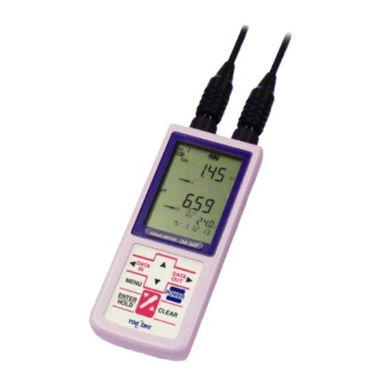
- Page 1 Handheld Multi-Parameter Water Quality Meter MODEL WQC-30 ●Please read this manual thoroughly before use to use it correctly. ●This manual should be provided to the person who actually operate this product. No. WQC-LB16300E...
- Page 2 Introduction Introduction (a) Thank you for purchasing this product from our company. This “Model WQC-30 Handheld Multi-Parameter Water Quality Meter” (referred to below as “the instrument” or “the product”) has a waterproof construction suitable for performing on-site measurements, and is equipped with clock functionality and data memory functionality essential for data management.
-
Page 3: Safety Information
Model WQC-30 Safety Information Safety Information (1) Meaning of symbols The meanings of signal terms and symbol types related to warnings in this instruction manual are as follows: Symbol alert marks on labels on the product etc. ( : Pictorial symbols for general warnings), not only alert to the possibility of injury or damage, but should also be read as “Please refer to the... - Page 4 Model WQC-30 Safety Information (2) Matters relating to safety compliance ●Do not use in places where explosive gases, flammable gases etc. Explosion・ outbreak of fire・ are present. leakage of ●Do not place the product in a fire or attempt to burn it. There is a risk liquids that the product will explode.
-
Page 5: Working With The Instruction Manual
Model WQC-30 Safety Information inserting the dissolved oxygen electrode into the sensor module, always discharge the static electricity from your body. After insertion into the sensor module, and during maintenance inspections, always discharge the static electricity from your body prior to handling so that the membrane set is not subjected to electrostatic discharge. - Page 6 Model WQC-30 Safety Information (3) Working with the instruction manual This instruction manual includes important information such as “Matters relating to safety compliance”. Please handle it as follows. (a) The instruction manual is intended not only for initial operation, but also for subsequent operation, maintenance, failure etc.
-
Page 7: Product Warranty
Product warranty (1) Applicable to this warranty DKK-TOA CORPORATION (hereinafter referred to as “the Company”) guarantees that the product will operate satisfactorily as in the Company’s prescribed specifications (hereinafter referred to as “the Specifications”). Failures that occur during the warranty period will be repaired free of charge. -
Page 8: Reading This Manual
Model WQC-30 Reading this manual Reading this manual To gain an overview of this product and get it started etc., please refer to the necessary items in this instruction manual. The circled numbers in the diagram indicate the chief items which need to be referred to in order. -
Page 9: Table Of Contents
Model WQC-30 Table of contents Table of contents ●Introduction ·················································································· 1 ●Safety Information ······································································ 2 (1) Meaning of symbols … 2 (2) Matters relating to safety compliance … 2 (3) Working with the instruction manual … 4 ●Product warranty ········································································ 5 ●Reading this manual... - Page 10 Model WQC-30 Table of contents 5.2 Measurement procedure ························································· 39 5.3 Power on/off ········································································· 48 (1) Power on … 48 (2) Power off … 49 5.4 Date and time adjustment ························································ 50 5.5 Switching measurement types ·················································· 52 5.6 Hold and release measurement values ······································· 54 5.7 Manual memory operation with measurement values ····················...
- Page 11 Model WQC-30 Table of contents (3) Dissolved Oxygen Span Calibration in Water Vapor Saturated Air … 105 (4) Dissolved Oxygen Span Calibration in Saturated Water … 108 (5) Zero Calibration of Dissolved Oxygen … 111 (6) Two-Point Calibration of Dissolved Oxygen … 116 (7) Confirmation of Dissolved Oxygen Calibration Data …...
- Page 12 Model WQC-30 Table of contents (1) Setting dissolved oxygen measurement on/off … 152 (2) Changing the dissolved oxygen mode … 153 (3) Changing dissolved oxygen salinity correction … 154 (4) Changing dissolved oxygen atmospheric pressure correction … 154 (5) Changing dissolved oxygen display resolution … 157 (6) Setting dissolved oxygen saturation formula …...
- Page 13 Model WQC-30 Table of contents (1) Daily care … 190 (2) Care in the case of long term storage … 190 (3) Taking care of dirty cathode surfaces … 191 9.5 Replacement of each part of pH electrodes ······························· 192 (1) Replacing the internal solution for reference electrode …...
-
Page 14: Package Contents
Model WQC-30 1. Package Contents 1. Package Contents The following table lists the package contents for the standard products. Optional items such as the dissolved oxygen electrode and the submersible stirrer are not included. Package contents list Model name Classification... -
Page 15: Specifications And Functions
Model WQC-30 2. Specifications and Functions 2. Specifications and Functions (1) Specifications Heading Details Product name Handheld Multi-Parameter Water Quality Meter Model name WQC-30 pH: glass electrode method Measurement method Temperature: thermistor resistor type Turbidity: 90° scattered light method Electrical conductivity: AC four electrode method... - Page 16 RS-232C isolator (signal isolation unit) is required between the instrument unit (WQC-30) and the connected RS-232C equipment (personal computer, sequencer, etc.). This is because the measured values may be affected by ground loops (signal currents circulating through the earth).
- Page 17 *6: In cases where the sample being measured is grounded (when measuring sea, ponds, rivers, built-in metal tanks etc.), a commercially available RS-232C isolator (signal isolation unit) is required between the instrument unit (WQC-30) and the connected RS-232C equipment (personal computer, sequencer, etc.) 【IMPORTANT】...
-
Page 18: Functions
Model WQC-30 2. Specifications and Functions (2) Functions Heading Details Clock function Internal Data memory Up to 200 data sets (measurement date/time, temperature value, measured value) can be recorded. Interval memory Measurement values are periodically recorded. • Cancel interval memory (OFF) •... -
Page 19: Name And Function Of Each Part
Model WQC-30 3. Name and Function of Each Part 3. Name and Function of Each Part (1) Instrument unit and control panel Connector for sensor connection I/O cover Display section AC adapter cover Battery cover Control panel <Front> <Back> Up key... -
Page 20: Display Sections
Model WQC-30 3. Name and Function of Each Part (Continued) Key type Function (notation in the manual) • Switches to [Menu Screen]. Menu key ( Up key, down key • The measurement type display switches. • Numerical change (increase/decrease) and function selection switches. - Page 21 Model WQC-30 3. Name and Function of Each Part Name and function of each display section Notation Number Name Function in the manual Data number display • Displays the data number. Battery symbol • Displays the remaining battery level in 4 stages.
- Page 22 Model WQC-30 3. Name and Function of Each Part (Continued) Notation Number Name Function in the manual MODE symbol • Illuminates when switching the turbidity measurement units (NTU, mg/L). • Illuminates when switching the dissolved oxygen measurement units (mg/L, %).
-
Page 23: Sensor Module (Model Wms-30)
Model WQC-30 3. Name and Function of Each Part (3) Sensor module (Model WMS-30) 10 Dummy cap (without dissolved oxygen electrode) 2 Hook 3 Protective cylinder 4 Cable fixing ring 7 Turbidity sensor Electrode part 6 Electrical conductivity cell 11 Reinforcing band... -
Page 24: Ph Electrode
Model WQC-30 3. Name and Function of Each Part (4) pH electrode pH electrode Part names and descriptions for pH electrode Number Name Description Glass electrode chip • pH sensitive part • Protects the glass membrane when using pH electrode. -
Page 25: Turbidity Sensor, Electrical Conductivity Cell And Temperature Sensor
Model WQC-30 3. Name and Function of Each Part (5) Turbidity sensor, electrical conductivity cell and temperature sensor Turbidity sensor, electrical conductivity cell and temperature sensor Part names and description for turbidity sensor, electrical conductivity cell and temperature sensor Number... - Page 26 Model WQC-30 3. Name and Function of Each Part Part names and description for dissolved oxygen electrode Number Name Description Diaphragm set • Cap for the tip where the oxygen permeable membranes are set Dissolved oxygen • Cylinder housing electrolyte where the diaphragm set is installed...
-
Page 27: Preparation
Model WQC-30 4.1 Battery installation 4. Preparation (a) After opening the packaging and removing the product, please make the necessary preparations so that it may be used at any time. (b) When using the submersible stirrer (optional), please perform the preparation as outlined in “8.4 Submersible stirrer”. - Page 28 Model WQC-30 4.1 Battery installation Battery mounting part Battery (2quantity) Installing the batteries ③ Installing the packing …… Make sure that the packing is correctly installed inside the battery cover. Checking the packing installation 【IMPORTANT】 • Clean out any dirt or dust which has gathered around the packing and the rib (the part sealing the packing).
- Page 29 Model WQC-30 4.1 Battery installation ④ Attaching the battery cover …… Attach the battery cover as before, securely inserting the tip of the battery cover press-point into the battery cover recess. Install battery cover Hook the claw on the battery cover...
-
Page 30: Affixing And Removing The Protective Cover (Optional)
Model WQC-30 4.2 Affixing and removing the protective cover (optional) 4.2 Affixing and removing the protective cover (optional) ●Handle the instrument unit carefully to avoid damage. If Injury damaged accidentally, fragments may cause injury. 【IMPORTANT】 • Please affix and remove the protective cover on a desk or similar so as not to drop the instrument unit. - Page 31 Model WQC-30 4.2 Affixing and removing the protective cover (optional) ② Push out the instrument unit …… apply the index finger and the middle finger in the long finger-hold recess and push out the instrument unit with the thumb. Instrument unit (back side)
-
Page 32: Connecting The Sensor Module
Model WQC-30 4.3 Connecting the sensor module 4.3 Connecting the sensor module ●Always check that the power is off before attaching/detaching Fire/electric shock the plug, battery cover, AC adapter cover, or input-output cover. If water or chemicals enter the internal parts of the instrument unit, there is a risk of short-circuit causing fire. - Page 33 Model WQC-30 4.3 Connecting the sensor module ① Confirm the power is off …… Please check that the power supply of the instrument unit is off. ② Inserting the plug …… Insert the sensor module connector in a straight line such that the “○”...
-
Page 34: Installation Of The Dissolved Oxygen Electrode (Optional)
Model WQC-30 4.4 Installation of the dissolved oxygen electrode (optional) Installation of the dissolved oxygen electrode (optional) ●The dissolved oxygen measurement circuit of the sensor Electrostatic discharge module uses parts that may fail from incurring damage due static electricity. Static electricity may be discharged from... - Page 35 Model WQC-30 4.4 Installation of the dissolved oxygen electrode (optional) Remove the label and the electrode outer cylinder ② Confirm the secure attachment of the diaphragm set …… Lightly turn the tip diaphragm set clockwise to check that it is tight. If it feels secure with light turning then this should be sufficient.
- Page 36 Model WQC-30 4.4 Installation of the dissolved oxygen electrode (optional) ④ Attach the electrode outer cylinder …… Tilt so that the air bleed groove of the electrode body faces up and, in order that no bubbles will remain, slowly and gently screw on the electrode outer cylinder until it comes to a stop.
- Page 37 Model WQC-30 4.4 Installation of the dissolved oxygen electrode (optional) Incorporation of the dissolved oxygen electrode ⑧ Insert the dissolved oxygen electrode …… Insert the dissolved oxygen electrode into the mounting hole of the “c” port, then turn it lightly to drive it in until it stops when it is aligned with the connector alignment groove.
-
Page 38: Basic Operation
Model WQC-30 5.1 Key points of use 5. Basic Operation 5.1 Key points of use Please bear in mind the following points when using this product. ●When working at measurement sites avoid risk of falling by Falling using a safety belt. Also, to avoid injury, wear a helmet, life-jacket, safety shoes etc. - Page 39 Model WQC-30 5.1 Key points of use (Continued) • Immerse the sensor module deeper into the sample than the upper holes of the protective cylinder. It is possible to lower it to depths of up to 30m. Lower and raise it slowly.
-
Page 40: Measurement Procedure
Model WQC-30 5.2 Measurement procedure 5.2 Measurement procedure (a) An example describing taking this product from the workplace or storage location to the measurement site where measurements are performed will be used to explain the operations in sequence. (b) Dissolved oxygen measurement (optional) …… If the dissolved oxygen electrode is attached to sensor module, dissolved oxygen can be measured. - Page 41 Model WQC-30 5.2 Measurement procedure ② Confirm performance of maintenance inspections …… Confirm that the everyday maintenance inspections are being performed. If any of these operations have not been performed then perform them at this stage. >>“9. Maintenance and inspections”...
- Page 42 Model WQC-30 5.2 Measurement procedure ⑤ Remove protective cylinder and protective cap …… Turn the protective cylinder counterclockwise (viewing from below) to remove it. When performing pH measurements, also remove the protective cap. • Retain the protective cap after removal. It will be used again after the measurement is completed.
- Page 43 Model WQC-30 5.2 Measurement procedure • Confirm interval memory disabled …… The interval memory is a function to automatically record all types of measurement value at a regular time interval set by the user. While fully illuminated on the screen (running state), and also when it is flashing (stopped state), measurement values cannot be recorded by auto hold etc.
- Page 44 Model WQC-30 5.2 Measurement procedure ⑩ Attach the protective cylinder …… Securely screw the protective cylinder firmly back into position on the sensor module body. ●If the protective cylinder loosens and comes off in the measuring Contamination by foreign tank, procedures for dealing with foreign materials may become objects necessary and damage may result.
- Page 45 Model WQC-30 5.2 Measurement procedure ⑫ Switching measurement types …… On the [Measurement Screen], press on the control panel repeatedly to set the necessary “measurement type screen”. >>“5.5 Switching measurement types” • Press once and the measurement type on the [Measurement Type Screen] will change.
- Page 46 Model WQC-30 5.2 Measurement procedure Data number display (the number of Battery symbol measured values to be recorded next) Main indication Turbidity area (pH measurement value measurement pH Measurement value values) indication display AUTO RANGE Standard liquid symbol bottle symbol...
- Page 47 Model WQC-30 5.2 Measurement procedure [c] The recorded measurement values can be recalled after returning to the workplace or storage location. >>“5.8 Checking, printing and erasing memory data” ⑮ Continue measuring …… To continue measuring, repeat the operations “ ⑪ to ⑬ ”.
- Page 48 Model WQC-30 5.2 Measurement procedure [Operations to be performed upon returning to the workplace or storage location] ⑲ Data management …… This is processing such as connecting the printer to the instrument unit and printing out the data. >>“5.8 Checking, printing and erasing memory data”, “8.2 Printing with the external printer”, “8.3 Communication via RS-232C”...
-
Page 49: Power On/Off
Model WQC-30 5.3 Power on/off 5.3 Power on/off (1) Power on The product can be turned on (ON) using the procedure in the following table. Power on procedure Operation Screen example ① Confirm the display is off … Confirm the display is off. -
Page 50: Power Off
Model WQC-30 5.3 Power on/off (2) Power off (a) The product can be turned off (OFF) using the procedure in the following table. (b) If on the screen is illuminated or flashing, then before powering off, release the interval memory. (>>“7.3 (4) Releasing the interval memory”... -
Page 51: Date And Time Adjustment
Model WQC-30 5.4 Date and time adjustment 5.4 Date and time adjustment (a) The date and time display can be set to the current date and time using the following procedure. (b) The year is AD and the time uses the 24 hours system. When the “ ⑥ To confirm” operation is performed it switches to the set time. - Page 52 Model WQC-30 5.4 Date and time adjustment (Continued) Operation Screen example ⑤ Change the date and time … On the [Date/Time Setting Screen], the place which flashes can be changed, so to change the numbers “add 1 minute to the present time” etc.
-
Page 53: Switching Measurement Types
Model WQC-30 5.5 Switching measurement types 5.5 Switching measurement types (a) For each measurement type, there is a [Measurement Screen] such as [pH Measurement Screen]. By switching between these screens, you can check the measured values for each type. (b) The operation screen map is different for each measurement item. >>“7.1 Operation screen maps”... - Page 54 Model WQC-30 5.5 Switching measurement types (Continued) Operation Screen example Salinity Measurement Salinity Measurement Screen pH Measurement Option Screen pH Measurement Screen Option Screen Turbidity Measurement Dissolved Oxygen Dissolved Oxygen Measurements Turbidity Measurement Screen Type Screen Measurements Option Screen Screen(displayed only when...
-
Page 55: Hold And Release Measurement Values
Model WQC-30 5.6 Hold and release measurement values 5.6 Hold and release measurement values (a) The measurement value display for all measurement types can be temporarily put in the hold state. By using hold (HOLD), you can read and note down the measured values of all items at the time of key operation without worrying about time. - Page 56 Model WQC-30 5.6 Hold and release measurement values (Continued) Operation Screen example ⑤ To enter hold state … Press on the control panel. • If is illuminated then the measurement values for all types of measurement (main display) enter the hold sate.
-
Page 57: Manual Memory Operation With Measurement Values
Model WQC-30 5.7 Manual memory operation with measurement values Manual memory operation with measurement values (a) At any time, you can record (in memory) all types of measured values by key operation. With this operation, measurement value hold (HOLD) is not performed. Afterwards, the measurement values displayed will continue to change from moment to moment. - Page 58 Model WQC-30 5.7 Manual memory operation with measurement values (Continued) Operation Screen example ⑤ Record Measurement value … Press on the control panel. • All types of the measurement values are recorded and the data number at the upper left of the screen (the number of the next recorded measurement value) will increase by 1.
-
Page 59: Checking, Printing And Erasing Memory Data
Model WQC-30 5.8 Checking, printing and erasing memory data 5.8 Checking, printing and erasing memory data (a) Recorded measurement values (memory data) can be checked by specifying and calling their number. It is also possible to print and erase recorded measurement values. - Page 60 Model WQC-30 5.8 Checking, printing and erasing memory data (Continued) Operation Screen example Memory Data Display Screen • To print or erase displayed data, proceed to operation “⑥”. To print or erase a specified range of memory data, proceed to “⑦ Specify a range of Memory data”.
-
Page 61: Calibration
Model WQC-30 6.1 Calibration of pH 6. Calibration The calibration procedure varies depending on measurement items for pH, turbidity, electrical conductivity, temperature or dissolved oxygen (option). Because salinity measurement is performed by converting the electric conductivity measurement value, no calibrating function only for salinity measurement is provided. -
Page 62: Ph Calibration Procedure
Model WQC-30 6.1 Calibration of pH (f) If the interval memory is enabled (lit or blinking on the screen ), it is not possible to perform calibration. Disable it. >> “7.3 (2) Changing the interval method and time” INT. symbol (g) Prior to calibration, check if maintenance inspection is routinely carried out. - Page 63 Model WQC-30 6.1 Calibration of pH 【IMPORTANT】 • Fill the pH standard solution up to the line “H” level of the beaker. ② Clean the electrode parts …… Remove the sensor module protective cylinder and the electrode cap of pH electrode, and wash thoroughly clean the pH electrode and the other electrode parts with pure water (or tap water).
- Page 64 Model WQC-30 6.1 Calibration of pH pH Measurement Items screen pH Measurement screen • If you use this for the first time after purchase, or if the standard solution bottle symbol is already deleted, you need not execute the operation stated in “⑤” below. Proceed the step “⑥...
- Page 65 Model WQC-30 6.1 Calibration of pH 【IMPORTANT】 • Slowly put the electrode of the sensor module into calibration beaker. Forcible immersion may cause to break the electrode. • If unreasonable force should be applied to the sensor module with the electrode in the beaker, the electrode may be broken.
-
Page 66: Ph Calibration Data Check
Model WQC-30 6.1 Calibration of pH • For one-point calibration, “⑧, ⑨” operations are not necessary. Proceed to “⑩ Clean electrode parts”. ⑧ Clean electrode parts …… Clean the electrode and its parts thoroughly with pure water (or tap water) and thoroughly wash away pH standard solution. After cleaning, please wipe off moisture gently with a paper wipe or similar. - Page 67 Model WQC-30 6.1 Calibration of pH (Continued) Operation Screen example ③ Go to [pH Measurement screen] … On the [Measurement screen], repeat pressing the until [pH Measurement Items screen] appears. • After about one second of this operation, the [pH Measurement screen] appears.
- Page 68 Model WQC-30 6.1 Calibration of pH (Continued) Operation Screen example Two-point calibration data change One-point calibration data …… [Calibration Value Display - Date Time screen] → [Calibration Value Display - Standard Solution Potential 1 screen] Two-point calibration data …… [Calibration Value Display - Date Time screen] → [Calibration Value Display - Standard Solution Potential 1 screen] →...
-
Page 69: Deletion Of Ph Calibration Data
Model WQC-30 6.1 Calibration of pH (4) Deletion of pH Calibration Data (a) The standard solution bottle symbol such as on the [pH measurement screen] indicates that the data of the latest one calibration are saved. 【IMPORTANT】 • Prior to calibration, always delete the calibration data. If previous calibration data remains, it may affect the new calibration. -
Page 70: Change Of Ph Standard Solution
Model WQC-30 6.1 Calibration of pH (Continued) Operation Screen example Screens before and after calibration data deletion • After this operation, the blinking on the screen changes to lighting, the standard solution bottle symbol goes out, and [pH Measurement screen] appears. - Page 71 Model WQC-30 6.1 Calibration of pH (Continued) Operation Screen example ② Check for interval memory release … On the [Measurement screen], ensure that the is blinking or lighting. If it is illuminated, release or cancel the interval memory. >> “7.3 (3) Execution and termination of interval INT.
- Page 72 Model WQC-30 6.1 Calibration of pH (Continued) Operation Screen example Screens for setting of pH standards olutions types ⑧ Go to [Measurement screen] … Press less than 2 seconds). • If you want to go back to [Menu screen], press...
-
Page 73: Calibration Of Turbidity
Model WQC-30 6.2 Calibration of Turbidity 6.2 Calibration of Turbidity (1) Key points of Turbidity Calibration (a) Use the following turbidity calibrating procedures specifically for specific purposes. • One-touch zero calibration … … A usual calibration required to be performed before measurement. -
Page 74: One-Touch Zero Calibration Of Turbidity
Model WQC-30 6.2 Calibration of Turbidity (2) One-Touch Zero Calibration of Turbidity This one-touch zero calibration can be performed on the site of measurement. ① Pour pure water into the container ……Pour pure water into a 2000ml tall beaker (or an equivalent container (200mm or deeper). - Page 75 Model WQC-30 6.2 Calibration of Turbidity ③ Attaching the cylinder …… Re-attach the sensor module protective cylinder as it was before. 【IMPORTANT】 • Be sure to attach the protective cylinder. If the cylinder is removed, proper calibration cannot be performed.
- Page 76 Model WQC-30 6.2 Calibration of Turbidity Selection of [Turbidity Measurement screen] ⑦ Execute one-touch zero calibration ……After making sure that at least 30 seconds have passed since the power supply ON of the instrument and that the value indicated on it is stable, press and hold for at least 2 seconds.
-
Page 77: Span Calibration Of Turbidity
Model WQC-30 6.2 Calibration of Turbidity (3) Span Calibration of Turbidity (a) Usually, the completion of one-touch zero calibration may be continuously followed by a turbidity measurement. However, if a measured value shows discrepancy or if the obtained value needs to be made compatible with a value from other method, perform span calibration in addition to the one-touch zero calibration. - Page 78 Model WQC-30 6.2 Calibration of Turbidity ④ Turbidity standard solution onto stirrer ……Transfer the turbidity standard solution to a 2000mL tall beaker or a similar container (200mm or deeper), and place the beaker on a stirrer. ⑤ Stir turbidity standard solution ……Set a stirring element in the container, where the...
- Page 79 Model WQC-30 6.2 Calibration of Turbidity ⑧ Go to [Turbidity Measurement screen] ……On the [Measurement screen], press to change the screen to [Turbidity Measurement Items screen] (turb). Selection of [Turbidity Measurement screen] • After this operation, leave the operation panel untouched for about one second, then the [Turbidity Measurement screen] ( (with “NTU”...
- Page 80 Model WQC-30 6.2 Calibration of Turbidity Using formazin standard solution 800 NTU (high concentration)……800NTU Using formazin standard solution 80 NTU (low concentration)………80NTU Using high-concentration kaolin standard solution……800mg/L Using low-concentration kaolin standard solution……80mg/L • The main indication shows an actually measured value of the concentration of the turbidity standard solution, and also shows that the [Span Calibration Execution screen] has replaced.
-
Page 81: Preparation Of Formazine Standard Solution
Model WQC-30 6.2 Calibration of Turbidity (4) Preparation of Formazin Standard Solution (a) Select a turbidity standard solution depending on the range of the sample to be measured. • Formazin standard solution 800NTU …… if the measurement is mainly in a high range (80 to 800NTU) •... -
Page 82: Preparation Of Kaolin Standard Solution
Model WQC-30 6.2 Calibration of Turbidity (5) Preparation of Kaolin Standard Solution Prepare a kaolin standard solution by appropriately diluting a commercial refined kaolin suspension. 〔Note〕• Kaolin varies in grain diameter, grain size, and grain shape depending on its origin and on how it was refined. - Page 83 Model WQC-30 6.2 Calibration of Turbidity (Continued) Operation Screen example ⑤ Go to [Calibration Value Display screen] …On the [Menu screen], press a few times until on the screen blinks, and press Turbidity [Menu screen] • After this operation, the [Calibration Value Indication - Date Time screen] appears.
-
Page 84: Deletion Turbidity Calibration Data
Model WQC-30 6.2 Calibration of Turbidity (Continued) Operation Screen example Display of calibration value - Display of calibration value - Display of calibration value - Display of calibration value - zero turbidity value screen zero mV value screen span turbidity value screen... - Page 85 Model WQC-30 6.2 Calibration of Turbidity (Continued) Operation Screen example ② Check for interval memory release … On the [Measurement screen], ensure that the blinking or lighting. If it is illuminated, release or cancel the interval memory. >> “7.3 (3) Execution and INT.
-
Page 86: Calibration Of Electrical Conductivity
Model WQC-30 6.3 Calibration of Electrical Conductivity 6.3 Calibration of Electrical Conductivity (1) Key points of Electrical Conductivity Calibration (a) The electrical conductivity measuring system does not require routine calibration. You can use the instrument in its condition as default. - Page 87 Model WQC-30 6.3 Calibration of Electrical Conductivity ① Solution C for checking into beaker …… Transfer the Solution C for checking to the calibration beaker up to its line S level. Pour solution C for checking into calibration beaker ② Clean electrode parts ……...
- Page 88 Model WQC-30 6.3 Calibration of Electrical Conductivity ③ Immerse electrode parts in Solution C for checking … … With the protective cylinder of the sensor module removed, immerse the electrode parts in the beaker containing the Solution C for checking, move them up, down, right and left a few times, and then lower them until the middle level of the reinforcing band is flush with the brim of the beaker.
- Page 89 Model WQC-30 6.3 Calibration of Electrical Conductivity ⑤ Go to [Electrical Conductivity Measurement screen] … … On the [Measurement screen], press to change the screen to the [Electrical Conductivity Measurement Items screen]. • If, following the above step, the operation panel is left untouched for about 1 second, the screen changes to [Electrical Conductivity Measurement screen] (“mS/m”...
-
Page 90: Cell Constant Calibration
Model WQC-30 6.3 Calibration of Electrical Conductivity ⑧ Measure, again, Solution C for checking …… >> from “ ③ Immerse electrode parts in Solution C for checking” through “⑥ Check measured value” • If the measured value is in the good range , the operation “⑨” is not required. Proceed, then, to “⑩... - Page 91 Model WQC-30 6.3 Calibration of Electrical Conductivity ③ Clean electrode parts …… Remove the sensor module protective cylinder and the electrical conductivity sleeve, clean the electrical conductivity cell and other electrode parts with pure water, and gently wipe them with paper wiper.
- Page 92 Model WQC-30 6.3 Calibration of Electrical Conductivity ⑥ Power supply ON …… If the display is off, press and hold the on the control panel for 2 seconds or more (until a beep is heard). • It takes 20 to 30 seconds after turning on the power for the functions of the instrument unit to stabilize.
- Page 93 Model WQC-30 6.3 Calibration of Electrical Conductivity ⑩ Go to [Calibration Solution Value Input screen] …… After ensuring that the power supply has been on for at least 30 seconds, wait until main indication on the [Cell Constant Calibration screen] is stabilized, and the press for at least 2 seconds.
- Page 94 Model WQC-30 6.3 Calibration of Electrical Conductivity ⑫ Set a calibration solution value …… On the [Calibration Solution Value Input screen], press for less than 2 seconds after making sure of the input value. • The buzzer sounds, and the [Cell Constant (after the calibration) screen] appears.
-
Page 95: Preparation Of Cell Constant Calibration Solution
Model WQC-30 6.3 Calibration of Electrical Conductivity (4) Preparation of Cell Constant Calibration Solution (a) For the cell constant calibration, the following reagent and utensils must be prepared, and a potassium chloride calibration solution must be accurately prepared. (b) This product is designed to exhibit its best performance when the cell constants are calibrated at 140.9mS/m. -
Page 96: Electrical Conductivity Calibration Data Check
Model WQC-30 6.3 Calibration of Electrical Conductivity (5) Electrical Conductivity Calibration Data Check (a) Data of the latest one calibration are saved. The data are of the calibration date and time and the cell constant after the calibration. You can check these data. - Page 97 Model WQC-30 6.3 Calibration of Electrical Conductivity (Continued) Operation Screen example • If the calibration value is already deleted or calibration is not performed yet, “− − − −” will be indicated. Calibration data of electrical conductivity ⑦ Go to [Measurement screen] …...
-
Page 98: Temperature Calibration
Model WQC-30 6.4 Temperature Calibration 6.4 Temperature Calibration (a) Usually, no temperature calibration is required. (b) If you want to match the temperature indication of this product with a temperature measured using a different standard thermometer, you can do it by this temperature calibration (one-point calibration). - Page 99 Model WQC-30 6.4 Temperature Calibration (Continued) Operation Screen example If from [Salt Content Measurement screen] … Once If from [Dissolved Oxygen Measurement screen] … 2 times ⑤ Select temperature calibration ON or OFF …On the [Temperature Calibration screen], press change the screen to necessary one of the following screens.
- Page 100 Model WQC-30 6.4 Temperature Calibration (Continued) Operation Screen example ⑦ Set changed calibration temperature value …Press • This step effectuates the calibration value change in the case of temperature calibration ON/OFF or ON. ⑧ Go to [Measurement screen] …… Press (for less than 2 seconds).
-
Page 101: Calibration Of Dissolved Oxygen (Optional)
Model WQC-30 6.5 Calibration of Dissolved Oxygen (optional) 6.5 Calibration of Dissolved Oxygen (optional) 【IMPORTANT】 • In any of the following conditions, connect the instrument main body and the sensor module, turn ON the dissolved oxygen measurement, and leave them in that state for about 6 hours before starting the calibration. - Page 102 Model WQC-30 6.5 Calibration of Dissolved Oxygen (optional) (c) Always calibrate before measuring dissolved oxygen In usual measurement, “dissolved oxygen span calibration” utilizing the proximate constancy of the atmosphere will suffice. For others, refer to the instructions listed below to carry out your calibration suited for the type of measurement.
- Page 103 Model WQC-30 6.5 Calibration of Dissolved Oxygen (optional) 【IMPORTANT】 • The data of the last (previous) calibration, if left undeleted prior to the current calibration, can affect current calibration data. • In the two-point calibration, carry out the zero calibration after deleting the data of the last (previous) calibration in the course of the zero calibration.
-
Page 104: Dissolved Oxygen Span Calibration With Air
Model WQC-30 6.5 Calibration of Dissolved Oxygen (optional) (2) Dissolved Oxygen Span Calibration with Air (a) This span calibration assumes that the oxygen concentration in the air is almost constant. This calibration can be performed with the dissolved oxygen electrodes placed in the air, and preparation of standard solution and others is not required. - Page 105 Model WQC-30 6.5 Calibration of Dissolved Oxygen (optional) ③ Delete calibration data …… Delete the saved calibration data. >> “6.5 (8) Dissolving Oxygen Calibration Data Deleting Procedure” 【IMPORTANT】 • Prior to calibration, always delete the calibration data. The deletion is followed by the return of all the dissolved oxygen calibration data to the default values.
-
Page 106: Saturated Air
Model WQC-30 6.5 Calibration of Dissolved Oxygen (optional) [Span Calibration Execution screen], and [Dissolved Oxygen Measurement screen] after completion of the span calibration ⑦ Check span calibration completion …… Ensure that the has changed to lighting, is lighting, and the [Dissolved Oxygen Measurement screen] has replaced. - Page 107 Model WQC-30 6.5 Calibration of Dissolved Oxygen (optional) ② Clean electrode parts …… Remove the sensor module protective cylinder, clean the electrode parts including the dissolved oxygen electrode with pure water, and gently wipe them with paper wiper or similar.
- Page 108 Model WQC-30 6.5 Calibration of Dissolved Oxygen (optional) ④ Power supply ON …… If the display is off, press and hold the on the control panel for 2 seconds or more (until a beep is heard). • It takes 20 to 30 seconds after turning on the power for the functions of the instrument unit to stabilize.
-
Page 109: Dissolved Oxygen Span Calibration In Saturated Water
Model WQC-30 6.5 Calibration of Dissolved Oxygen (optional) ⑦ Execute span calibration …… After setting the sensor module electrode parts in the calibration beaker, leave them to stand for at least 20 seconds, and then press on the [Dissolved Oxygen Measurement screen] for at least 2 seconds (until a beep is heard). - Page 110 Model WQC-30 6.5 Calibration of Dissolved Oxygen (optional) ① Prepare saturated water …… Transfer approx. 2000mL of pure water to a 2000mL volumetric beaker or the like, place a stirring element in the beaker, and feed air by an air pump while stirring the water by a stirrer until the central portion of the water surface is much depressed.
- Page 111 Model WQC-30 6.5 Calibration of Dissolved Oxygen (optional) ③ Sensor module into the saturated water …… With the protective cylinder removed, place and hold the sensor module in the saturated water beaker. 【IMPORTANT】 • If air bubbles are sticking to the diaphragm of the dissolved oxygen electrode, they can impair the calibration.
-
Page 112: Zero Calibration Of Dissolved Oxygen
Model WQC-30 6.5 Calibration of Dissolved Oxygen (optional) ⑦ Execute span calibration ……On the [Dissolved Oxygen Measurement screen], press for at least 2 seconds (until a beep is heard). • The [Span Calibration Execution screen] replaces, the blinks, and the span calibration begins. - Page 113 Model WQC-30 6.5 Calibration of Dissolved Oxygen (optional) ① Prepare zero calibration solution …… Pour pure water in the calibration beaker up to a level of line H on the beaker (below which the diaphragm is fully immersed). Then, weigh 8 g of commercial sodium sulfite into the beaker, and dissolve it by stirring with a glass rod.
- Page 114 Model WQC-30 6.5 Calibration of Dissolved Oxygen (optional) 【IMPORTANT】 • Do not touch the diaphragm surface directly with hand. • Carefully handle the electrode parts, now exposed with the cylinder removed, to avoid their contact with and damage by others.
- Page 115 Model WQC-30 6.5 Calibration of Dissolved Oxygen (optional) Selection of [Dissolved Oxygen Measurement screen] • If you use this instrument for the first time after purchase of it, or if the span calibration mark and the zero calibration mark are already dark, the following “⑥” operation is not necessary.
- Page 116 Model WQC-30 6.5 Calibration of Dissolved Oxygen (optional) ⑧ Confirm completion of zero calibration …… Make sure on the screen that the blinking of the has changed to lighting, the has lighted, and the [Dissolved Oxygen Measurement screen] has replaced.
-
Page 117: Two-Point Calibration Of Dissolved Oxygen
Model WQC-30 6.5 Calibration of Dissolved Oxygen (optional) (6) Two-Point Calibration of Dissolved Oxygen (a) If you want to measure accurately in a wide range, perform the two-point calibration. The two-point calibration is a combination of the zero calibration and the span calibration. - Page 118 Model WQC-30 6.5 Calibration of Dissolved Oxygen (optional) “6.5 (4) ① Prepare saturated water” “6.5 (4) ② Clean electrode parts” “6.5 (4) ③ Sensor module into saturated water” (Operations not required: “6.5 (4) ④ to ⑥”) “6.5 (4) ⑦ Execute span calibration”...
-
Page 119: Confirmation Of Dissolved Oxygen Calibration Data
Model WQC-30 6.5 Calibration of Dissolved Oxygen (optional) (7) Confirmation of Dissolved Oxygen Calibration Data (a) The on the [dissolved Oxygen Measurement screen] shows that the zero calibration data of the latest one zero calibration or span calibration are saved. You can call and check the data. -
Page 120: Deletion Of Dissolved Oxygen Calibration Data
Model WQC-30 6.5 Calibration of Dissolved Oxygen (optional) (Continued) Operation Screen example ⑥ Check calibration data … While repeatedly pressing on the [Calibration Value Display - Date Time screen], check the calibration data. • The data are indicated in the order as follows: [Calibration Value Display - Date Time screen] →... - Page 121 Model WQC-30 6.5 Calibration of Dissolved Oxygen (optional) (b) If is not displayed on the screen, such as when this instrument is used for the first time after purchase of it, the following operation is not necessary. Dissolved oxygen calibration data deleting procedure...
- Page 122 Model WQC-30 6.5 Calibration of Dissolved Oxygen (optional) (Continued) Operation Screen example ⑤ Delete calibration data …While the is blinking on the [Zero/Span Calibration Execution screen], press Screens before and after calibration data deletion • Following the operation step above, the blinking of the...
-
Page 123: Various Functions
Model WQC-30 7.1 Operation screen maps 7. Various functions 7.1 Operation screen maps (1) pH operation screen map ◎ If you press any screen (less than 2 seconds), return directly to the [Measurement screen]. Power on(ON) (Press for at least 2 seconds) -
Page 124: Turbidity Operation Screen Map
Model WQC-30 7.1 Operation screen maps (2) Turbidity operation screen map POWER ◎ If you press any screen (less than 2 seconds), return directly to the [Measurement screen]. Power on(ON) (Press for at least 2 seconds) [Hold state] [Measurement HOLD... -
Page 125: Electrical Conductivity Operation Screen Map
Model WQC-30 7.1 Operation screen maps (3) Electrical conductivity operation screen map ◎ If you press POWER any screen (less than 2 seconds), return directly to the [Measurement screen]. Power on(ON) (Press for at least 2 seconds) [Hold state] [Measurement... -
Page 126: Salinity Operation Screen Map
Model WQC-30 7.1 Operation screen maps (4) Salinity operation screen map ◎ If you press any screen (less than 2 seconds), return directly to the [Measurement screen]. POWER Power on(ON) (Press for at least 2 seconds) [Hold state] [Measurement Screen]... -
Page 127: Dissolved Oxygen Operation Screen Map
Model WQC-30 7.1 Operation screen maps (5) Dissolved oxygen operation screen map ◎ If you press any screen (less than 2 seconds), return directly to the [Measurement screen]. POWER Power on(ON) (2Press for at least 2 seconds) [Hold state] [ M e a s u r e m e n t... -
Page 128: Data Memory Functions
Model WQC-30 7.2 Data memory functions 7.2 Data memory functions The followings are the functions for data memory. Please refer if necessary. “5.6 Hold and release measurement values” …… Holds and records (in memory) measurement values. “5.7 Manual memory operation with measurement values”... - Page 129 Model WQC-30 7.2 Data memory functions Example2 Last Next Subsequent measurement measurement measurement value value value (Changed arbitrarily) Number (d) The set number is applied to the following records. • Simultaneous recording with hold operation with • Recording with • Automatic recording with interval memory.
- Page 130 Model WQC-30 7.2 Data memory functions (Continued) Operation Screen example ③ Entering number after change … Enter the number you wish to assign to the next recorded measurement value. To increase or decrease the flashing number: move flashing position: Setting range: 1 to 200 (default: 1) •...
-
Page 131: Changing Memory Overwrite On/Off
Model WQC-30 7.2 Data memory functions (2) Changing memory overwrite on/off (a) The upper limit for the number of measurement value record (memory) is 200. You can set whether to overwrite the old record (ON) (default) or not (OFF) when this limit is exceeded. -
Page 132: Changing The Interval Memory
Model WQC-30 7.3 Changing the interval memory 7.3 Changing the interval memory (1) Key points concerning interval memory (a) The interval memory is a function to automatically record all types of measurement value at a regular time interval set by the user. -
Page 133: Changing The Interval Method And Time
Model WQC-30 7.3 Changing the interval memory (2) Changing the interval method and time (a) You can activate (Shrt, Long)/deactivate (oFF) the interval and change the interval time. Changing the interval mode to “oFF” is essentially same as the operation described in “7.3 (4) Releasing the interval memory”. - Page 134 Model WQC-30 7.3 Changing the interval memory (Continued) Operation Screen example ③ Changing interval method … Press the control panel in the [Setting Interval Screen], then the interval method icons to be selected on the control panel starts flashing. Setting range: oFF … interval memory disabled (default) Shrt …...
- Page 135 Model WQC-30 7.3 Changing the interval memory (Continued) Operation Screen example ⑤ Confirming interval method … Press on the control panel in the [Setting Interval Screen]. • When “Shrt” or “Long” is selected, [Measurement Screen] appears in the interval standby state (with flashing).
-
Page 136: Execution And Termination Of Interval Memory
Model WQC-30 7.3 Changing the interval memory (3) Execution and termination of interval memory (a) When the interval memory is executed, it automatically records measurement values as memory data with the time interval set by the user. Stopping the execution sets the interval memory to the standby state. - Page 137 Model WQC-30 7.3 Changing the interval memory (Continued) Operation Screen example ③ Checking interval method and time … Confirm that “Shrt” or “Long” is flashing and the appropriate interval time is specified in the [Setting Interval Screen]. • To change the interval method and time, refer to “7.3 (2) Changing the interval method and time”.
- Page 138 Model WQC-30 7.3 Changing the interval memory (Continued) Operation Screen example ⑤ Starting interval memory … Press the control panel in the [Measurement Screen] ( with flashing). • After this operation, switches to continuous lighting from flashing, and the interval memory is executed.
-
Page 139: Releasing The Interval Memory
Model WQC-30 7.3 Changing the interval memory (Continued) Operation Screen example ⑦ Resuming … To resume the stopped interval memory, press on the control panel in the [Measurement Screen] ( turned on). • After this operation, switches to continuous lighting from flashing, and the interval memory is executed again. - Page 140 Model WQC-30 7.3 Changing the interval memory (Continued) Operation Screen example ③ Go to [Setting Interval Screen] … Press on the control panel in [Menu Screen] for several times until starts flashing, then press Menu Screen (Example of pH measurement) •...
-
Page 141: Set Buzzer On/Off
Model WQC-30 7.4 Setting buzzer on/off 7.4 Setting buzzer on/off The buzzer beeps to confirm the key operation or notify the operation is completed. This buzzer on/off (ON/OFF) can be changed. Steps for changing buzzer on/off Operation Screen example ① Go to [Menu Screen] … Press... -
Page 142: Set Auto Power Off
Model WQC-30 7.5 Setting auto power off 7.5 Setting auto power off (a) The Auto Power Off is the function is to automatically turn off the power (OFF) when there is no key operations during the set time period. (b) The Auto Power Off is not available while the interval memory is executed. It is also unavailable when the power is supplied by an AC adapter or a RS-232C connection cable, or a connection cable for external printer is connected. - Page 143 Model WQC-30 7.5 Setting auto power off (Continued) Operation Screen example Setting Auto Power Off Screen ④ Go to [Measurement Screen] … Check the setting and press on the control panel. • Press instead of to return to [Menu Screen]...
-
Page 144: Special Turbidity Functions
Model WQC-30 7.6 Special turbidity functions 7.6 Special turbidity functions (1) Changing turbidity units (a) You can switch between two types of measurement units for turbidity. The reference material to be used varies depending on the unit. “NTU” …… measurement using formazin as a reference material. (default) “mg/L”... -
Page 145: Switching The Display Range
Model WQC-30 7.6 Special turbidity functions (Continued) Operation Screen example blink [Menu Screen] for turbidity measurement ④ Changing Turbidity Unit … Press on the control panel then the changed unit starts flashing. Setting item: NTU (default) mg/L ⑤ Go to [Measurement Screen] …... - Page 146 Model WQC-30 7.6 Special turbidity functions (Continued) Operation Screen example ② Go to [Menu Screen] … Press on the control pane of the [Measurement Screen] in “Measurement State” (with turned off) . ③ Changing to flash … If any icons except...
-
Page 147: Special Electrical Conductivity Functions
Model WQC-30 7.7 Special electrical conductivity functions 7.7 Special electrical conductivity functions (1) Switching range (a) The measurement range can be switched between two; Auto range and Manual range. (b) In the Auto Range, the range moves up to the next level when measurement values exceed the current upper limit of measurement range. - Page 148 Model WQC-30 7.7 Special electrical conductivity functions (Continued) Operation Screen example ② Changing to [Measurement State] … Confirm that it is in the [Measurement Screen] in [Measurement State] (with turned off). • Press for two seconds or longer to show [Measurement Screen] when power is off (OFF).
-
Page 149: Changing The Temperature Compensation/Temperature Coefficient
Model WQC-30 7.7 Special electrical conductivity functions (2) Changing the temperature compensation/temperature coefficient (a) Turn it off (OFF) when measuring in a constant temperature reservoir to keep the temperature of specimen constant or when measuring as an emergency measure for errors in a temperature sensor. - Page 150 Model WQC-30 7.7 Special electrical conductivity functions (Continued) Operation Screen example ⑤ Select the type of temperature compensation … Press to select one of two types of screens for temperature compensations according your measurement purpose (>>“Types measurement compensation and setting screen” table).
-
Page 151: Changing Between Old And New Units
Model WQC-30 7.7 Special electrical conductivity functions (3) Changing between old and new units You can switch the indication in the old unit of electrical conductivity (S/cm) to new SI unit (S/m). Steps for changing old unit to new Operation Screen example ①... -
Page 152: Special Salinity Functions
Model WQC-30 7.8 Special salinity functions 7.8 Special salinity functions (1) Setting salinity units Change salinity unit setting. You can select from % (converted to NaCl) and no unit (PSS: practical salinity). 〔Notes〕• The electrical conductivity is converted to NaCl concentration in the salinity measurement (NaCl). -
Page 153: Special Dissolved Oxygen Functions (Optional)
Model WQC-30 7.9 Special dissolved oxygen functions (optional) 7.9 Special dissolved oxygen functions (optional) (1) Setting dissolved oxygen measurement on/off (a) Turn this setting on (ON) only when the dissolved oxygen electrode (optional) is connected to the sensor module. The dissolved oxygen measurement circuit is stopped to conserve power. -
Page 154: Changing The Dissolved Oxygen Mode
Model WQC-30 7.9 Special dissolved oxygen functions (optional) (2) Changing the dissolved oxygen mode You can switch between the dissolved oxygen (mg/L) mode and the saturation rate (%) mode. Steps for switching to dissolved oxygen mode Operation Screen example ① Go to [Dissolved Oxygen Measurement Screen] …... -
Page 155: Changing Dissolved Oxygen Salinity Correction
Model WQC-30 7.9 Special dissolved oxygen functions (optional) (3) Changing dissolved oxygen salinity correction The dissolved oxygen value is corrected based on the salinity measurement values. When to measure dissolved oxygen in a solution with salinity, turning the salinity correction setting on (ON) results in the more accurate measurement. - Page 156 Model WQC-30 7.9 Special dissolved oxygen functions (optional) Steps for setting atmospheric pressure correction on/off and changing correction value Operation Screen example ① Go to [Dissolved Oxygen Screen] … Press on the control panel for several times in the [Measurement Screen] of “Measurement Screen” (with turned off).
- Page 157 Model WQC-30 7.9 Special dissolved oxygen functions (optional) (Continued) Operation Screen example ⑥ Entering correction value … Confirm that the current correction value is flashing and enter the desired correction value. • Press on the control to move the flashing digit.
-
Page 158: Changing Dissolved Oxygen Display Resolution
Model WQC-30 7.9 Special dissolved oxygen functions (optional) (5) Changing dissolved oxygen display resolution If there are some errors in the lowest digit of dissolved oxygen (mg/L) measurement values due to an influence from the sample, you can use the function to delete the lowest digit (rounding off). Keep in mind that this function is available only for the measurement in mg/L. - Page 159 Model WQC-30 7.9 Special dissolved oxygen functions (optional) (Continued) Operation Screen example ⑤ Select indication type for display resolution … Press on the control panel to select the indication type of the lowest digit. • Setting range: 0.00mg/L … display up to first decimal place 0.00mg/L …...
-
Page 160: Setting Dissolved Oxygen Saturation Formula
Model WQC-30 7.9 Special dissolved oxygen functions (optional) (6) Setting dissolved oxygen saturation formula You can select from the ISO5814:2012 compliant formula and the Truesdale formula. 〔Notes〕• The Truesdale formula is the traditional formula used in the previous JIS. Steps for setting dissolved oxygen saturation formula... - Page 161 Model WQC-30 7.9 Special dissolved oxygen functions (optional) (Continued) Operation Screen example ⑥ Go to [Setting Dissolved Oxygen Formula Screen] … Press on the control panel for several times in the other screen groups (with turned on) to show “CALC” in the data number indication area.
-
Page 162: Optional Equipment
Model WQC-30 8.1 Connecting the optional equipment 8. Optional equipment 8.1 Connecting the optional equipment (a) Optional equipment can be connected to the AC adapter, the external printer and the RS-232C connector cable. (b) The RS-232C of this product is non-isolated type. -
Page 163: Connecting External Printer Cable
Model WQC-30 8.1 Connecting the optional equipment (2) Connecting external printer cable The measurement and calibration result can be printed on the standard paper by connecting the external printer (optional) to the instrument unit. 【IMPORTANT】 • Use only our optional parts for the external printer connecting cable. Do not use any third party parts. - Page 164 (when measuring in sea, ponds, rivers, built-in metal tanks etc.), a commercially available RS-232C isolator (signal isolation unit) is required between the instrument unit (WQC-30) and the connected RS-232C equipment (such as personal computer and sequencer).
-
Page 165: Printing With External Printer
Model WQC-30 8.2 Printing with external printer 8.2 Printing with external printer The measurement data can be printed out by connecting to the external printer (optional) as follows. (1) Printing pH calibration value The calibration data is automatically printed out when a calibration is completed. >>“6.1 Calibration of pH”... -
Page 166: Printing Turbidity Calibration Values
Model WQC-30 8.2 Printing with external printer (2) Printing turbidity calibration values The calibration data is automatically printed out when a calibration is completed. >>“6.2 Calibration of Turbidity” Example of printing turbidity zero calibration after calibration Example of printing turbidity span calibration after calibration... -
Page 167: Printing The Electrical Conductivity Cell Constant Calibration Values
Model WQC-30 8.2 Printing with external printer (3) Printing the electrical conductivity cell constant calibration values Press on the control panel in [Calibration Value Display Screen] to print calibration data (Example of printing electrical conductivity cell constant calibration values after calibration). >>“6.3 (5) Electrical Conductivity Calibration Data Check”... -
Page 168: Printing Measurement Values
Model WQC-30 8.2 Printing with external printer You can print the set calibration data by pressing the Electrode key in the [Display Calibration Value Screen] if there are the set zero or span calibration data. >>“6.5 (7) Confirmation of Dissolved Oxygen Calibration Data”... - Page 169 Model WQC-30 8.2 Printing with external printer (c) Printing memory data with data memory function You can save the measurement values in the field and print it later. >>“5.8 Checking, printing and erasing memory data” (i) Printing specific memory data...
- Page 170 Model WQC-30 8.2 Printing with external printer (ii) Printing memory data consecutively You can print memory data consecutively by specifying the number range. Steps for printing memory data consecutively Operation Screen example ① Go to [Memory Data Display Screen] … Press on the control panel in the [Measurement Screen].
- Page 171 Model WQC-30 8.2 Printing with external printer (Continued) Operation Screen example ⑤ To stop printing … Turning power off of the instrument unit and the external printer (optional). ⑥ Reverting … Press (up to two seconds) after printing is finished. It returns to [Measurement Screen].
-
Page 172: Communication Via Rs-232C
Model WQC-30 8.3 Communication via RS-232C 8.3 Communication via RS-232C The Auto Power Off function is disabled when connecting with the RS-232C connecting cable. 〔Note〕• Our connection cable for RS-232C is non-isolated type. In cases where the sample to measure is grounded (when measuring sea, ponds, rivers, built-in metal tanks etc.), a commercially available... - Page 173 Model WQC-30 8.3 Communication via RS-232C ⑧ Electrical conductivity measurement unit (fixed value) 1 byte 0: Electrical conductivity ⑨ Electrical conductivity compensation 1 byte 0: OFF A: ATC ⑩ Electrical conductivity value 5 byte ⑪ Electrical conductivity unit 1 byte 0: µS/(c)m 1: mS/(c)m 2: S/(c)m ⑫...
- Page 174 Model WQC-30 8.3 Communication via RS-232C ⑨ Turbidity display range 1 byte 0: no floating point 1:first decimal point ⑩ Turbidity unit 1 byte 0: NTU 1: mg/L ⑪ Electrical conductivity measurement unit (fixed value) 1 byte 0: Electrical conductivity ⑫...
- Page 175 Model WQC-30 8.3 Communication via RS-232C ■Setting date • PC to instrument unit RT, 20171030, 123400 CRLF ① ② ③ ①: Setting code RT 2 byte ②: Date 8 byte ③: Time, minute and second 6 byte • Instrument unit to PC RT, 20171030, 123400, OK CRLF ①...
- Page 176 Model WQC-30 8.3 Communication via RS-232C • Instrument unit to PC 〔Reply from Q02〕 Q02,0001CRLF ① ② ① Request code 3 byte ② Data number 4 byte 〔Reply from Q11〕 Q11,WQC-30 CRLF ① ② ① Request code 3 byte ② instrument unit model name 10 byte Left aligned and empty part is space 〔Reply from Q12〕...
-
Page 177: Data Recording Software
Model WQC-30 8.3 Communication via RS-232C (2) Data recording software (a) Our data recording software GP-LOG (optional) is available to load measurement data to PC in the CSV format, when connecting this instrument to PC. (b) You can create a chart or a graph from the data saved with this software using the commercial spreadsheet software. -
Page 178: Submersible Stirrer
Model WQC-30 8.4 Submersible stirrer 8.4 Submersible stirrer (1) Part names of submersible stirrer Sensor module Connect the sensor module with this screw. Stirrer support cylinder Stirrer bar Stirring content Stirrer protection cylinder Dry cell (C battery) Stirrer holder Protective... -
Page 179: Installing Or Replacing Batteries
Model WQC-30 8.4 Submersible stirrer (d) A stirrer bar is attached using a magnet to the mixer unit. Attach it back to the mixer unit if falls out of the mixer unit. 【IMPORTANT】 • Without a stirrer bar, mixing operation can not be performed. - Page 180 Model WQC-30 8.4 Submersible stirrer ② Pulling out mixer unit …… Turn the stirrer holder counterclockwise (looking from bottom) to remove and pull out the mixer unit gently. 【IMPORTANT】 • If you jerk out the mixer unit, it may cause the lead wire to snap.
- Page 181 Model WQC-30 8.4 Submersible stirrer ⑥ Removing float stopper …… Turn the float switch protection cover counterclockwise (looking from bottom) to remove. • Set aside the float stopper since it can be used repeatedly. Stirrer holder Float switch protective cover...
-
Page 182: Steps For Using The Submersible Stirrer
Model WQC-30 8.4 Submersible stirrer ⑧ Completing submersible stirrer operation …… Put the float switch back to the float axis and screw in the float switch protective cover to the protective cylinder of the stirrer firmly. 【IMPORTANT】 • The float stopper should be attached whenever the submersible stirrer is not in use. - Page 183 Model WQC-30 8.4 Submersible stirrer Sensor module Male Screw male screw A into screw A this female screw. Protective cylinder (remove) Stirrer support cylinder Stirrer bar Stirrer protection cylinder Float Mounting sensor module ●The total weight of the submersible stirrer with the sensor module is Injuries approx.
- Page 184 Model WQC-30 8.4 Submersible stirrer ⑥ Mounting float stopper …… >>figure “Mounting and removing float stopper” in 8.4 (3) ①. 【IMPORTANT】 • The float stopper should be attached whenever the submersible stirrer is not in use. If it is not attached, and the stirrer is laid down or it touches the float, the stirrer moves and consumes energy.
-
Page 185: Maintenance And Inspections
Model WQC-30 9.1 Taking care of instrument unit 9. Maintenance and inspections 9.1 Taking care of instrument unit Use a soft and dry cloth or tissue paper to clean the instrument unit. For heavy soil, mount the sensor module, the battery cover, the AC adapter cover and the I/O cover in the appropriate position and wipe them with a soft cloth such as gauze soaked in a dish wash detergent solution and wrung it dry. -
Page 186: Taking Care Of Ph Electrode
Model WQC-30 9.2 Taking care of pH electrode 9.2 Taking care of pH electrode ●The hydrochloric acid used to wash the electrode is a hazardous Hazardous substances substance. Wear protective equipment when handling it. Be sure to check the safety data sheet (SDS). -
Page 187: Taking Care Of Dirty Electrodes
Model WQC-30 9.2 Taking care of pH electrode • When it is not used for a long period of time. • When it is stored in pure water for a long period of time. • When it is rinsed with the hydrochloric acid. - Page 188 Model WQC-30 9.2 Taking care of pH electrode Above the window frame of the protective cover. Soak until here. 6mol/L However, within 10 Hydrochloric acid minutes. solution For heavy soil, soak it in the hydrochloric acid solution to clean. (b) Grease Wipe the tip of electrode with a soft cloth such as gauze dampened with some organic solvent such as ethanol, and rinse with pure water, then soak in pure water for 2 to 3 hours.
-
Page 189: Temperature Sensors
Model WQC-30 9.3 Taking care of turbidity sensors, electrical conductivity cells and temperature sensors Taking care of turbidity sensors, electrical conductivity cells and temperature sensors 【IMPORTANT】 • Never use any abrasive powders such as a cleanser or organic solvent such as ethanol to clean turbidity sensors, electrical conductivity cells and temperature sensors. -
Page 190: How To Clean Heavily Soiled Cell
Model WQC-30 9.3 Taking care of turbidity sensors, electrical conductivity cells and temperature sensors (2) How to clean heavily soiled cell Clean the cell as follows since soiled cells cause measurement errors. ① Rinsing with pure water …… Remove the protective cylinder of the sensor module and rinse the light receiving/emitting part of turbidity sensor, the temperature sensor and the electrode metal part and the outer cylinder of the electrical conductivity cell thoroughly with pure water. -
Page 191: Taking Care Of The Dissolved Oxygen Electrode (Optional)
Model WQC-30 9.4 Taking care of the dissolved oxygen electrode (optional) 9.4 Taking care of the dissolved oxygen electrode (optional) (1) Daily care If it is not used for a short period of time (less than 2 months), follow the steps below to complete measurement. -
Page 192: Taking Care Of Dirty Cathode Surfaces
Model WQC-30 9.4 Taking care of the dissolved oxygen electrode (optional) (3) Taking care of dirty cathode surfaces If calibration fails or the response is extremely slow even after replacing the electolyte/diaphragm set, the electrode cathode might be soiled. Opposite position to working electrode (a) Taking care of cathode ①... -
Page 193: Replacement Of Each Part Of Ph Electrodes
Model WQC-30 9.5 Replacement of each part of pH electrodes 9.5 Replacement of each part of pH electrodes ●The part of electrode is made of glass. Handle it with care not to Injuries damage it. If it is damaged accidentally, the broken fragments may cause injuries. -
Page 194: Replacement Of The Liquid Junction Section
Model WQC-30 9.5 Replacement of each part of pH electrodes ③ Supply new internal solution …… Fill in the new internal solution of the reference electrode gel from the inlet using the syringe with a nozzle to prevent air bubbles. Tighten the inlet cap firmly after filling it up. -
Page 195: Replacement Of The Glass Electrode Chip
Model WQC-30 9.5 Replacement of each part of pH electrodes (3) Replacement of the glass electrode chip Replace the electrode chip if there any cracks or damages on the glass electrode or the performance level is not restored after cleaning. -
Page 196: Replacement Of The Reference Electrode
Model WQC-30 9.5 Replacement of each part of pH electrodes (4) Replacement of the reference electrode Replace the reference electrode if the performance level is not restored after replacing the internal solution of reference electrode gel, the liquid junction section or the glass electrode tip. The reference electrode is the pH electrode without the glass electrode tip. - Page 197 Model WQC-30 9.5 Replacement of each part of pH electrodes ④ Checking internal solution …… Check the internal solution of the reference electrode gel is filled in the pH electrode with the new reference electrode mounted. 【IMPORTANT】 • If there are any air bubbles larger than 3mm, push them out by filling the enclosed internal solution for reference electrode gel.
- Page 198 Model WQC-30 9.5 Replacement of each part of pH electrodes ⑥ Installing pH electrode …… Insert the pH electrode with new reference electrode mounted to the mounting hole indicated with “a” and align the thread by turning slightly and push ⑦...
-
Page 199: Replacement Of The Dissolved Oxygen Electrode (Optional)
Model WQC-30 9.6 Replacement of the dissolved oxygen electrode (optional) 9.6 Replacement of the dissolved oxygen electrode (optional) ●Be careful when mounting the dissolved oxygen electrode. There Injuries are risk of injury by the four claws on the tip of the diaphragm set, if you have your hands slip. -
Page 200: Diaphragm Set
Model WQC-30 9.6 Replacement of the dissolved oxygen electrode (optional) (1) Replacement of dissolved oxygen electrode electrolyte and diaphragm set The electrolyte and diaphragm set of the dissolved oxygen electrode should be replaced every four months or so. Removing diaphragm set ①... - Page 201 Model WQC-30 9.6 Replacement of the dissolved oxygen electrode (optional) ⑥ Filling up electrolyte …… Fill up the supplied electrolyte up to the lower end of the thread of the electrode outer cylinder. O ring Apply silicon grease lightly. Electrode unit...
-
Page 202: Replacement Of The Dissolved Oxygen Electrode
Model WQC-30 9.6 Replacement of the dissolved oxygen electrode (optional) (2) Replacement of the dissolved oxygen electrode Replace the dissolved oxygen electrode if the performance level is not restored even after replacing the electrolyte and the diaphragm or polishing the electrode. (Model: ELD-045) ①... -
Page 203: Replacement Of The Batteries
Model WQC-30 9.7 Replacement of the batteries 9.7 Replacement of the batteries (a) Replace or charge the battery when the battery icon indicates as No. 4 in the following table. >>“4.1 battery Installation” (b) The indication of remaining power differs between the AA alkali dry cell and the AA rechargeable nickel hydrogen battery, use it as a reference only. -
Page 204: Troubleshooting
Model WQC-30 10.1 Safety measures in error 10. Troubleshooting 10.1 Safety measures in error Pull out the battery from the product when any abnormal operation is detected. Also, if you are using the AC adapter (optional), pull it out from the power plug. -
Page 205: Error Messages
Model WQC-30 10.2 Error messages 10.2 Error messages (a) This instrument unit is equipped with the error message function to notify any operation or system errors. ERROR When an error occurs, the icon starts flashing, and the error number is shown in the indication area and the [Error Message Screen] appears. - Page 206 Model WQC-30 10.2 Error messages (Continued) Error Details Cause Action Number Temperature • The variance against the • Check the temperature setting. calibration error temperature setting exceeds ±5ºC. pH potential stability • The pH electrode is not • Insert the pH electrode correctly in the standard...
- Page 207 Model WQC-30 10.2 Error messages (Continued) Error Details Cause Action Number • Deterioration of standard • Replace the standard solution. solution or wrong concentration. • Wear or damage on the pH • Replace the pH electrode. >>“9.5 Replacement electrode. of each part of pH electrodes”...
- Page 208 Model WQC-30 10.2 Error messages (Continued) Error Details Cause Action Number Turbidity zero • The measurement input value • Replace the pure water for calibration with the calibration error from the turbidity sensor is too new one. large during the one touch zero •...
- Page 209 Model WQC-30 10.2 Error messages (Continued) Error Details Cause Action Number • Dirty detection electrode plane • Clean the working electrode plane. >>9.4 (3) of dissolved oxygen electrode. Taking care of dirty cathode surfaces • Wear or damage on the •...
- Page 210 Model WQC-30 10.2 Error messages (Continued) Error Details Cause Action Number • Deterioration of electrolyte • Replace the electrolyte. >>“9.6 (1) Replacement of dissolved oxygen electrode electrolyte and diaphragm set” • Dirty detection electrode plane • Clean the detection electrode plane. >>9.4 (3) of dissolved electrode.
-
Page 211: Measures To Be Taken In The Case Of Other Problems
Model WQC-30 10.3 Measures to be taken in the case of other problems 10.3 Measures to be taken in the case of other problems (a) For any troubles with no error numbers, see “Measures to be taken in the case of other problems” for the problem, the cause and the measures in the following table. - Page 212 Model WQC-30 10.3 Measures to be taken in the case of other problems (Continued) Problem Cause Action • Soiled electrode, cell or sensor. • Clean the electrode, cell or sensor. >>“9.2 Taking care of pH electrode”, “9.3 Taking care of turbidity sensors, electrical conductivity cells and temperature sensors”...
- Page 213 Model WQC-30 10.3 Measures to be taken in the case of other problems (Continued) Problem Cause Action • Damaged diaphragm of dissolved • Replace the diaphragm set. >>“9.6 (1) oxygen electrode. Replacement of dissolved oxygen electrode electrolyte and diaphragm set”...
- Page 214 Model WQC-30 10.3 Measures to be taken in the case of other problems (Continued) Problem Cause Action • Measurements indication is out of Measurement • Connect the electrode correctly. range. values flash in the • Replace the electrode, the cell or the sensor.
-
Page 215: System Reset
Model WQC-30 10.4 System reset 10.4 System reset (a) When the instrument unit stop responding or indicated value are incorrect, resetting the system might solve the problem. (b) There are two ways to reset the system. In either way, press to turn off (OFF) the power of the instrument unit and keep the instrument unit and the sensor module connected. -
Page 216: Transportation, Storage, Disposal
Model WQC-30 11.1 Transportation 11. Transportation, storage and disposal 11.1 Transportation 【IMPORTANT】 • Use the box with which the product was delivered. Do not drop or tip over the box or put any heavy objects on top of the box. It will cause a failure. -
Page 217: Storage
Model WQC-30 11.2 Storage 11.2 Storage ●Do not use in any place where explosive or inflammable gas is Explosion/ignitio present. electric ●Do not place the product in a fire or attempt to burn it. There is a risk shock/liquid spill of explosions or ignition inside the product. -
Page 218: Disposal
Model WQC-30 11.3 Disposal 11.3 Disposal Follow the local regulations when disposing this product or reagent. Contact your local municipal agency for details. ●Do not place the product and the battery in a fire or attempt to burn it. Explosion/ rupture There is a risk of explosion or rupture. -
Page 219: Parts/Option List
Model WQC-30 12. Parts/option list 12. Parts/option list To purchase parts or optional items, contact the sales agency you purchased this product. Have the item name, the model name and the quantity ready before contacting them. Parts list (standard parts list) - Page 220 Model WQC-30 12. Parts/option list pH/List of standard solution Model name Unit of Item name Note Code No. sales Phthalate standard solution 143F191 pH 4.01 500mL Neutral phosphate standard solution 143F192 pH 6.86 500mL Borate standard solution 143F193 pH 9.18 500mL...
- Page 221 Model WQC-30 12. Parts/option list Option list Model name Unit of Item name Note Code No. sales AC100V 50/60Hz AC adapter 7472990K With connecting cable External printer EPS-P30 Non-thermal paper Paper for external printer P000119 1 pack (20 rolls) Sold individually...
- Page 222 Revision History Instruction manual No. 26/04/2017 (HS) New Version in English WQC-LB16300E (RSL Tanaka/Ito) Print size: B5 (Original size: A4), Perfect bind - 221 -...
- Page 223 Head Office Address: 29-10, 1-Chome, Takadanobaba, Shinjuku-Ku, Tokyo, 169-8648 Japan Telephone: +81-3-3202-0225 Facsimile: +81-3-3202-5685 URL http://www.toadkk.co.jp/...
Need help?
Do you have a question about the WQC-30 and is the answer not in the manual?
Questions and answers