Table of Contents
Advertisement
https://appliancetechmanuals.com
ELECTROLUX SERVICE MANUAL
PLMV169DCC
In the interest of user-safety the oven should be restored to its original condition and only parts identical to those specified should
be used.
WARNING TO SERVICE PERSONNEL: Microwave ovens contain circuitry capable of producing very high voltage and
current. Contact with the following parts may result in a severe, possibly fatal, electrical shock. (High Voltage
Capacitor, High Voltage Power Transformer, Magnetron, High Voltage Rectifier Assembly, High Voltage Harness etc..)
BEFORE SERVICING ..................................................................................................... INSIDE FRONT COVER
WARNING TO SERVICE PERSONNEL .............................................................................................................. 1
MICROWAVE MEASUREMENT PROCEDURE .................................................................................................. 2
FOREWORD AND WARNING ................................................................................................................................3
PRODUCT SPECIFICATIONS ...............................................................................................................................4
GENERAL INFORMATION ...................................................................................................................................4
OPERATION .........................................................................................................................................................7
TROUBLESHOOTING GUIDE ............................................................................................................................. 12
TEST PROCEDURE ............................................................................................................................................ 14
TOUCH CONTROL PANEL ASSEMBLY ............................................................................................................. 26
COMPONENT REPLACEMENT AND ADJUSTMENT PROCEDURE .................................................................. 32
PICTORIAL DIAGRAM ........................................................................................................................................ 40
POWER UNIT CIRCUIT ....................................................................................................................................... 41
LSI UNIT CIRCUIT ............................................................................................................................................... 42
PRINTED WIRING BOARD ................................................................................................................................. 43
PARTS LIST ............................................................................................................................................ .44
PACKING AND ACCESSORIES...................................................................................................................48
This document has been published to be used for after sales service only. The contents are subject to change without notice.
Publication # 5995505376
TABLE OF CONTENTS
ELECTROLUX HOME PRODUCTS, INC.
P. O. Box 212378, Augusta, GA, 30917
800•944•9044
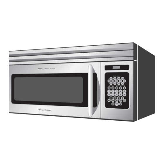
OVER THE RANGE
MICROWAVE OVEN
PLMV169DCC
MODEL
PLMV169DCC
S55M252V169DC
Page
P/N 316439256
Advertisement
Table of Contents

Related Manuals for Electrolux PLMV169DCC


Summary of Contents for Electrolux PLMV169DCC
-
Page 1: Table Of Contents
PARTS LIST .............................44 PACKING AND ACCESSORIES........................48 This document has been published to be used for after sales service only. The contents are subject to change without notice. ELECTROLUX HOME PRODUCTS, INC. P. O. Box 212378, Augusta, GA, 30917 800•944•9044... -
Page 2: Precautions To Be Observed Before And During Servicing To Avoid Possible Exposure To Excessive Microwave Energy
Before servicing an operative unit, perform a microwave emission check as per the Microwave Measurement Procedure outlined in this service manual. If microwave emissions level is in excess of the specified limit, contact ELECTROLUX HOME PRODUCTS, INC. immediately. If the unit operates with the door open, service person should 1) tell the user not to operate the oven and 2) contact ELECTROLUX HOME PRODUCTS, INC. -
Page 3: Warning To Service Personnel
PLMV169DCC WARNING TO SERVICE PERSONNEL Microwave ovens contain circuitry capable of pro- ducing very high voltage and current, contact with following parts may result in a severe, possibly fatal, electrical shock. (Example) High Voltage Capacitor, High Voltage Power Trans- former, Magnetron, High Voltage Rectifier Assem- bly, High Voltage Harness etc.. -
Page 4: Microwave Measurement Procedure
PLMV169DCC MICROWAVE MEASUREMENT PROCEDURE A. Requirements: 1) Microwave leakage limit (Power density limit): The power density of microwave radiation emitted by a microwave oven should not exceed 1mW/cm at any point 5cm or more from the external surface of the oven, measured prior to acquisition... -
Page 5: Foreword And Warning
PRODUCT DESCRIPTION OVER THE RANGE MICROWAVE OVEN PLMV169DCC GENERAL INFORMATION FOREWORD This Manual has been prepared to provide Electrolux Home Products OPERATION Service Personnel with Operation and Service Information for the ELECTROLUX OVER THE RANGE MICROWAVE OVEN, PLMV169DCC. TROUBLESHOOTING GUIDE AND... -
Page 6: Product Specifications
PLMV169DCC PRODUCT SPECIFICATION ITEM DESCRIPTION Power Requirements 120 Volts / 13.3 Amperes 60 Hertz Single phase, 3 wire grounded Power Output 1000 watts (IEC-705 TEST PROCEDURE) Operating frequency of 2450MHz Case Dimensions Width 29-15/16" Height 16-3/8" Depth 15- 1/16" (Not including the door handle) Cooking Cavity Dimensions Width 21"... - Page 7 PLMV169DCC Electrical Requirements The oven is equipped with a 3-prong grounding plug. DO NOT UNDER ANY CIRCUMSTANCES CUT OR REMOVE THE GROUNDING PIN FROM THE PLUG. The power supply cord and plug must be connected to a separate 120 Volt AC, 60 Hz, 15 Amp. or more dedicated line, using a grounded receptacle.
- Page 8 PLMV169DCC CONTROL PANEL PLMV169DCC...
-
Page 9: Operation
PLMV169DCC OPERATION DESCRIPTION OF OPERATING SEQUENCE The following is a description of component functions during of the primary interlock switch, and door sensing switch oven operation. is mechanically associated with the door so that it will function in the following sequence. - Page 10 PLMV169DCC program by touching one of the BREAKFAST, LUNCH, 3. RE-CIRCULATION (INSIDE VENTING) DINNER pads, and number pad to select menu. Enter the The air handing is the same as VERTICAL VENTING weight or quantity by touching the Number pads. When the...
- Page 11 PLMV169DCC any vapor from the oven cavity and sensor. NOTE: During this first stage, do not open the door or SENSOR COOKING CONDITION touch STOP/CLEAR pad. 4. When the sensor detects the vapor emitted from the Using the SENSOR function, food is cooked without figuring food, the display switches over to the remaining time, power level or quantity.
- Page 12 PLMV169DCC SCHEMATIC NOTE: CONDITION OF OVEN 1. DOOR CLOSED CLOCK APPEARS ON DISPLAY FUSE OVEN THERMAL CUT OUT CONTROL UNIT N.O. SECONDARY INTERLOCK RELAY POWER HOOD FAN TRANSFORMER THERMAL MAGNETRON STOP CUT OUT SWITCH OVEN High LAMP RELAY TURN-TABLE...
- Page 13 PLMV169DCC DESCRIPTION AND FUNCTION OF COMPONENTS CAUTION: BEFORE REPLACING A BLOWN C/T FUSE DOOR OPEN MECHANISM TEST THE DOOR SENSING SWITCH, The door is opened by pulling the door handle, refer to the SECONDARY INTERLOCK RELAY (RY2), Figure D-1.
-
Page 14: Troubleshooting Guide
PLMV169DCC The stirrer motor drives the stirrer fan to stir the microwave touching the WORK LIGHT pad or the NIGHT LIGHT pad. radiation from the waveguide. And also the brightness can be varied to high or low by touching the WORK LIGHT pad or the NIGHT LIGHT pad. - Page 15 https://appliancetechmanuals.com...
-
Page 16: Test Procedure
PLMV169DCC TEST PROCEDURES PROCEDURE COMPONENT TEST LETTER MAGNETRON ASSEMBLY TEST 1. Disconnect the power supply cord, and then remove outer case. 2. Open the door and block it open. 3. Discharge high voltage capacitor. 4. To test for an open filament, isolate the magnetron from the high voltage circuit. A continuity check across the magnetron filament leads should indicate less than 1 ohm. - Page 17 PLMV169DCC TEST PROCEDURES PROCEDURE COMPONENT TEST LETTER (HIGH VOLTAGES ARE PRESENT AT THE HIGH VOLTAGE TERMINAL, SO DO NOT ATTEMPT TO MEASURE THE FILAMENT AND HIGH VOLTAGE.) HIGH VOLTAGE RECTIFIER TEST 1. Disconnect the power supply cord, and then remove outer case.
- Page 18 PLMV169DCC TEST PROCEDURES PROCEDURE COMPONENT TEST LETTER CAUTION: IF THE TEMPERATURE FUSE INDICATES AN OPEN CIRCUIT AT ROOM TEMPERATURE, REPLACE TEMPERATURE FUSE. 5. If the C/T fuse is blown when the door is opened, check the secondary interlock relay, primary interlock switch and monitor switch according to the "TEST PROCEDURE"...
- Page 19 PLMV169DCC TEST PROCEDURES PROCEDURE COMPONENT TEST LETTER MONITOR SWITCH TEST 1. Disconnect the power supply cord, and then remove outer case. 2. Open the door and block it open. 3. Discharge high voltage capacitor. 4. Before performing this test, make sure that the secondary interlock switch and the primary interlock relay are operating properly, according to the above Switch Test Procedure.
- Page 20 PLMV169DCC TEST PROCEDURES PROCEDURE COMPONENT TEST LETTER HOOD THERMAL CUT-OUT TEST 1. Disconnect the power supply cord, and then remove outer case. 2. Open the door and block it open. 3. Discharge high voltage capacitor. 4. A continuity check across the thermal cut-out terminals should indicate an open circuit unless the...
- Page 21 PLMV169DCC TEST PROCEDURES PROCEDURE COMPONENT TEST LETTER TOUCH CONTROL PANEL ASSEMBLY TEST The touch control panel consists of circuits including semiconductors such as LSI, ICs, etc. Therefore, unlike conventional microwave ovens, proper maintenance cannot be performed with only a voltmeter and ohmmeter.
- Page 22 PLMV169DCC TEST PROCEDURES PROCEDURE COMPONENT TEST LETTER 6) Re-install the outer case (cabinet). 7) Reconnect the power supply cord after the outer case is installed. 8) Run the oven and check all functions. 2. Control Unit. The following symptoms indicate a defective control unit. Before replacing the control unit, perform the Key unit test (Procedure M) to determine if control unit is faulty.
- Page 23 PLMV169DCC TEST PROCEDURES PROCEDURE COMPONENT TEST LETTER RELAY TEST 1. Disconnect the power supply cord, and then remove outer case. 2. Open the door and block it open. 3. Discharge high voltage capacitor. 4. Disconnect the leads to the primary of the power transformer.
- Page 24 PLMV169DCC TEST PROCEDURES PROCEDURE COMPONENT TEST LETTER STEPS OCCURRENCE CAUSE OR CORRECTION Only pattern at "a" is broken. *Insert jumper wire J1 and solder. Pattern at "a" and "b" are broken. *Insert the coil RCILF2003YAZZ between "c" and "d".
- Page 25 PLMV169DCC TEST PROCEDURES PROCEDURE COMPONENT TEST LETTER AH SENSOR TEST Checking the initial sensor cooking condition WARNING :The oven should be fully assembled before following procedure. (1) The oven should be plugged in at least two minutes before sensor cooking.
- Page 26 PLMV169DCC CHECKING CONTROL UNIT (1) Disconnect the power supply cord, and then remove outer case. (2) Open the door and block it open. (3) Discharge high voltage capacitor. (4) Disconnect the sensor connector that is mounted to control panel.
- Page 27 PLMV169DCC TEST PROCEDURES PROCEDURE COMPONENT TEST LETTER NOISE FILTER TEST 1. Disconnect the power supply cord, and then remove outer case. 2. Open the door and block it open. 3. Discharge high voltage capacitor. 4. Disconnect the leads to the primary of the power transformer.
-
Page 28: Touch Control Panel Assembly
PLMV169DCC TOUCH CONTROL PANEL ASSEMBLY OUTLINE OF TOUCH CONTROL PANEL The touch control section consists of the following units 7) Relay Circuit as shown in the touch control panel circuit. To drive the magnetron, fan motor, stirrer motor, turntable motor, hood motor, and light the oven lamp and hood lamp. - Page 29 PLMV169DCC DESCRIPTION OF LSI LSI(IZA958DR) The I/O signal of the LSI(IZA958DR) is detailed in the following table. Pin No. Signal Description AN10 Signal coming from touch key. When either G10 line on key matrix is touched, a corresponding signal out of P10, P11, P12, P13, P14 and P17 will be input into AN10.
- Page 30 PLMV169DCC Pin No. Signal Description 20-22 P21-P23 Terminal not used. Oven lamp and Fan motor driving signal. To turn on and off the shut off relay(RY1). The square waveform voltage is delivered to the RY1 driving circuit and RY2 control circuit.
- Page 31 PLMV169DCC Pin No. Signal Description Signal similar to AN10. When either G13 line on key matrix is touched, acorresponding signal will be input into P41. Signal similar to AN10. When either G12 line on key matrix is touched, acorresponding signal will be input into P42.
- Page 32 PLMV169DCC ABSOLUTE HUMIDITY SENSOR CIRCUIT (1) Structure of Absolute Humidity Sensor balance the bridge circuit is deviated to increase the The absolute humidity sensor includes two thermistors voltage available at AN1 terminal of the LSI. as shown in the illustration. One thermistor is housed in...
- Page 33 PLMV169DCC SERVICING 1. Precautions for Handling Electronic Components 4) Re-install the outer case (cabinet). This unit uses CMOS LSI in the integral part of the 5) Re-connect the power supply cord after the outer circuits. When handling these parts, the following case is installed.
-
Page 34: Component Replacement And Adjustment Procedure
PLMV169DCC COMPONENT REPLACEMENT AND ADJUSTMENT PROCEDURE WARNING AGAINST HIGH VOLTAGE: Microwave ovens contain circuitry capable of producing very high voltage and current, contact with following parts may result in severe, possibly fatal, electric shock. (Example) High Voltage Capacitor, Power Transformer, Magnetron, High Voltage Rectifier Assembly, High Voltage Harness etc.. - Page 35 PLMV169DCC to remove. exhaust louver 5. Remove the louver covers A, B, and C from the hood 6. Now, the hood exhaust louver is free. REMOVAL OF OVEN FROM WALL (Two persons recommended to remove the oven) 1. Disconnect the power supply cord, and uncoil the power EXHAUST LOUVER REMOVAL".
- Page 36 PLMV169DCC 7. Disconnect the connector CN-F from the control unit. 16.Remove the lamp socket from the lamp angle. 8. Remove one (1) screw holding the hood duct to the oven 17.Pull the wire leads from the oven lamp socket by pushing cavity front plate.
- Page 37 PLMV169DCC THERMAL CUT-OUT (CAVITY) REMOVAL 1. Disconnect the power supply cord and remove the oven NOTE: When the tab is broken or turned off, use the another from wall and remove outer case. (Refer to procedure of tab which is fixed near the slit when the new thermal "Removal of Oven from Wall"...
- Page 38 PLMV169DCC 2. Hold the center of the bracket which supports the shaft of * Make sure that the axis of the shaft is not slanted. the fan motor on the flat table. 6. Install the hood duct to the oven cavity with the one (1) 3.
- Page 39 PLMV169DCC CONTROL PANEL ASSEMBLY, CONTROL UNIT AND KEY UNIT REMOVAL 1. Disconnect the power supply cord. fixing plate. 2. Open the door and block it open. 16.Release the one (1) tab holding the LCD to the LCD holder. 3. Remove one (1) screw holding the hood exhaust louver to 17.Release the four (4) tabs holding the LSI unit to the LCD...
- Page 40 PLMV169DCC DOOR SENSING SWITCH, PRIMARY INTERLOCK SWITCH, AND MONITOR SWITCH ADJUSTMENT the latched position. First check upper position of latch 1. Disconnect the power supply cord and remove the oven hook, pushing and pulling upper portion of door toward from wall and remove outer case.
- Page 41 PLMV169DCC Note: The door on a microwave oven is designed to act Hood Exhaust Louver as an electronic seal preventing the leakage of Upper Door Hige Pin microwave energy from oven cavity during cook cycle. This function does not require that door...
-
Page 42: Pictorial Diagram
https://appliancetechmanuals.com HOOD FAN MOTOR to Chassis Support CN-E N.O. 2 BLU Power Supply cord 120V 60Hz COM. DOOR SENSING SWITCH Blue 5 BLK Marking CN-C OVEN LAMP & SOCKET STIRRER MOTOR CAVITY THERMAL CONTROL UNIT CUT-OUT 3 YLW CN-B CN-E 9 PPL CT FUSE HIGH VOLTAGE COMPONENTS... -
Page 43: Power Unit Circuit
PLMV169DCC Figure S-2. Power Unit Circuit... -
Page 44: Lsi Unit Circuit
PLMV169DCC... -
Page 45: Printed Wiring Board
PLMV169DCC Figure S-5. Printed Wiring Board... -
Page 46: Parts List
PARTS LIST PLMV169DCC ∆ Note: The parts marked “ ” may cause undue microwave exposure. The parts marked “*” are used in voltage more than 250V. REF. NO. PART NO. DESCRIPTION Q'TY ELECTRIC PARTS FH-DZB015MRY0 High voltage rectifier assembly... - Page 47 PLMV169DCC REF. NO. PART NO. DESCRIPTION Q'TY DOOR PARTS CDORFB388MRK0 Door assembly FDORFB083MRT0 Door panel assembly Door frame assembly (not available in S/S) PGLSPB072MRE0 Front door glass LSTPPB030MRF0 Latch head LSTPPB032MRF0 Glass stopper MSPRTA046WRE0 Latch spring ∆ Door frame (not available in S/S)
- Page 48 PLMV169DCC OVEN AND CABINET PARTS...
- Page 49 PLMV169DCC CONTROL PANEL PARTS DOOR PARTS MISCELLANEOUS...
-
Page 50: Packing And Accessories
PLMV169DCC PACKING AND ACCESSORIES TOP PAD DOOR PROTECTOR WRAP COVER TURNTABLE TRAY DOOR PAD INSTALL MATERIAL ASSEMBLY RACK OPERATION MANUAL WALL TEMPLATE RACK HOLDER INSTALLATION INSTRUCTION TOP TEMPLATE GREASE FILTER (x 2) DAMPER ASSEMBLY BOTTOM PAD ACCESSORY HOLDER Non-replaceable items... - Page 51 PLMV169DCC NOTES...
- Page 52 PLMV169DCC ELECTROLUX COPYRIGHT © 2005 BY ELECTROLUX HOME PRODUCTS, INC. ALL RIGHTS RESERVED. No part of this publication may be reproduced, stored in retrieval systems, or transmitted in any form or by any means, electronic, mechanical, photocopying, recording, or otherwise, without prior written permission of the publisher.
Need help?
Do you have a question about the PLMV169DCC and is the answer not in the manual?
Questions and answers