
Subscribe to Our Youtube Channel
Related Manuals for Nilfisk-Advance ROS1300


Summary of Contents for Nilfisk-Advance ROS1300
- Page 1 ROS1300 Service Manual ROS1300 50000605/ 50000606/ 50000607 English 10/2021 (Rev.01) Form No. 55940922...
-
Page 2: Table Of Contents
Service Manual-ROS1300 Contents i Contents Contents ..................................i 03 General Information ............................. 5 Machine General Description ..........................5 Service Manual Purpose and Field of Application ....................5 Other Reference Manuals ............................. 5 Conventions ................................5 Service and Spare Parts ............................6 Serial Number Label .............................. - Page 3 Service Manual-ROS1300 Contents ii 20 Drive system ............................... 35 Functional Description ............................35 Wiring Diagram ..............................36 Component Locations ............................37 Troubleshooting ..............................38 Removal and Installation ............................. 40 Specifications ............................... 42 24 Electrical System ..............................43 Functional Description ............................43 Wiring Diagram ..............................
- Page 4 Service Manual-ROS1300 Contents iii Specifications ............................... 70 48 Side Sweeping System ............................71 Functional Description ............................71 Wiring Diagram ..............................71 Side Broom Actuator System ..........................72 Component Locations ............................72 Troubleshooting ..............................73 Removal and Installation ............................. 75 Specifications ............................... 77 50 Dust Control System ............................
-
Page 5: General Information
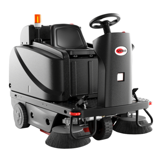
03 General Information Machine General Description The ROS1300 is a ride on commercial floor sweeping machine designed to sweep commercial floors. The machine is powered by on-board batteries. The machine is equipped with two side brooms and main broom, a spraying system a rear hopper, and vacuum suction. -
Page 6: Service And Spare Parts
Service Manual- ROS1300 03 General Information 6 Service and Spare Parts Service and repairs must be performed only by authorized personnel or Service Centers. The authorized personnel must be trained directly by the manufacturer and use original spare parts and accessories. Customers can find the Model No. -
Page 7: Safety
Service Manual- ROS1300 03 General Information 7 Safety Symbols It is important to read this manual before servicing the machine. It contains information for safety protection and preventive action. The symbols below are used to help you recognize this information. -
Page 8: Lifting Machine
Service Manual- ROS1300 03 General Information 8 Property Damage Messages – Storage and operation temperature must be above 0° C and humidity must be between 30% and 95%, non-condensing. – Before use, all doors and hoods should be properly latched. -
Page 9: Technical Data
Service Manual- ROS1300 03 General Information 9 Technical Data Parameter Value Machine length 1,680 mm /66.1Inches Machine width (without side brooms) 1,055 mm /41.5 Inches Machine maximum height 1,300 mm /51.2 Inches Cleaning width (without side brooms) 700 mm /27.6 Inches Cleaning width (with two side brooms) 1,350 mm /53.1 Inches... -
Page 10: Maintenance Schedule
Service Manual- ROS1300 03 General Information 10 Maintenance Schedule WARNING! Maintenance procedures must be performed after the machine is turned off and the battery charger cable is disconnected. In addition, carefully read the safety chapter in this instruction. SCHEDULED MAINTENANCE TABLE... -
Page 11: Machine Structure
Service Manual- ROS1300 03 General Information 11 Machine Structure... -
Page 12: Machine Structure (Continues)
Service Manual- ROS1300 03 General Information 12 Machine Structure (continues) -
Page 13: Control Panel
Service Manual- ROS1300 03 General Information 13 Control Panel 47. Multifunction display Items displayed: A) Pump/Vacuum motor/Side-broom separate running mode B) One-button start mode 0000.H 0000.H C) Safety stop mode (seat safety switch off) stop D) Reverse mode OFF. E) Braking/parking mode F) Battery charging mode 0000.H... -
Page 14: Service And Diagnostic Equipment
Service Manual- ROS1300 03 General Information 14 Service and Diagnostic Equipment Besides a complete set of standard tools, the following instruments are necessary to perform quick check and repairs on machines: Digital Voltmeter (DVM) Amp clamp with possibility of making DC measurements ... -
Page 15: Dimensions
Service Manual- ROS1300 03 General Information 15 Dimension 66.1 in [1680 mm]... -
Page 16: Control System
Service Manual- ROS1300 04 Control system 16 04 Control System Functional Description • The machine utilizes a Dash Board (EB1) to turn on Blue light(LED2(Optional)) • various machine functions and a Main Controller (EB2) Left-turn LED3& Right-turn LED4 • to control outputs. When Dash Board (EB1) receives... - Page 17 CAN Bus see the message but pay attention only to those messages they need to know about. The ROS1300 has 2 CAN Bus Nodes as Dash Board (EB1) and Main Controller (EB2). Dash Board (EB1) receives commands from operator and then transmit this information to Main Controller (EB2) through CAN Bus to perform them accordingly.
-
Page 18: Component Locations
Service Manual- ROS1300 04 Control system 18 Component Locations • Dash Board (EB1) • Warning light • Main Controller (EB2) • Main ground lug • USB charger (EB3) • Main +24V lug • Main contactor (K1) Dash Board (EB1) Main Controller (EB2) -
Page 19: Maintenance And Adjustments
Service Manual- ROS1300 04 Control system 19 Maintenance and Adjustments Access to Parameter Setting 1. Power off the machine. Press “Turn Left” and “Turn Right” button at the same time and power on the machine (Figure 1). 2. LCD will display “Input password” in 2 seconds, then release the two buttons (Figure 2). - Page 20 Service Manual- ROS1300 04 Control system 20 Confirm the password by pressing the button Figure 5 Figure 6 Press the buttons Press the buttons Figure 8 Figure 7 Press the buttons Figure 9...
- Page 21 Service Manual- ROS1300 04 Control system 21 Dash Board (EB1) and Main Controller (EB2) Parameter Setting The password to parameter setting of Dash Board (EB1) is “661”. Please refer to “Access to Parameter Setting” section (on page 19) for detailed description of parameter setting. The parameters whose serial numbers with “*” in the parameter setting tables can be modified.
-
Page 22: Troubleshooting
Service Manual- ROS1300 04 Control system 22 Troubleshooting Error Code List When an error message is detected by system, the LCD monitor on Dash Board will display the corresponding error number and description. After the problem is corrected, the display will disappear automatically. There is no history function to display error history at present. - Page 23 Service Manual- ROS1300 04 Control system 23 Error Error# Set conditions Diagnostics Initial action Description • Check if the supply voltage is Charger's input voltage normal, try plugging into another Error-14 AC power low Voltage <95V is low power outlet.
-
Page 24: Removal And Installation
Service Manual- ROS1300 04 Control system 24 Removal and Installation Warning! This procedure must be performed by qualified personnel only. Dash Board (EB1) 1. Disconnect the battery cable connection to the machine (Figure 1). 2. Prepare necessary tools, cross screwdriver, and socket spanner. - Page 25 Service Manual- ROS1300 04 Control System 25 Main Controller (EB2) 1. Prepare necessary tools, cross screwdriver. 2. Open the cover (Figure 1).and then disconnect battery power (Figure 4). 3. Disconnect all harnesses connected to Main Controller (Figure 2). 4. Remove 2 screws that are used for fixing Main Controller and take out Main Controller (Figure 3).
-
Page 26: Specifications
Service Manual- ROS1300 04 Control System 26 Specifications Sample Shop Voltage Measurement The following tables contain some “real world” shop voltage measurements to help you recognize what “normal” looks like. • Unless otherwise noted, all voltage readings are referenced to the main ground lug in the electrical bay. - Page 27 Service Manual- ROS1300 04 Control System 27 Dash Board (EB1) J4 Connector Pin# Color Function Condition Value Headlight &Blue Light GND ≈24V Headlight On Headlight power + output Headlight Off ≈24V Blue Light On Blue Light power + output Blue Light Off ≈12V...
- Page 28 Service Manual- ROS1300 04 Control System 28 Dash Board (EB1) J9 Connector Pin# Color Function Condition Value Speed limit pot high 2.2V Max. speed 2.1V BU-BK Speed limit pot in Min. speed 0.8V GR-BK Speed limit pot low 0.8V Dash Board (EB1) J20 Connector...
- Page 29 Service Manual- ROS1300 04 Control System 29 Main Controller (EB2) P2 Connector Pin# Color Function Condition Value Work, Ref 3 to 10 Filter shaker motor out1 +/- Filter shaker motor out2 +/- At rest, Ref 3 to 10 Active Slow down sensor 1 input Inactive ≈13V...
- Page 30 Service Manual- ROS1300 04 Control System 30 Main Controller (EB2) P4 Connector Pin# Color Function Condition Value ≈2.5V CAN-H ≈2.5V CAN-L Parameter Setting Without Password Some parameters in following table can be set without password. Please refer to following steps to set the parameters.
-
Page 31: Chassis System
Service Manual- ROS1300 10 Chassis System 31 10 Chassis System Functional Description chassis welded steel framework that provides the backbone structure on which the rest of the machine components are mounted. The chassis itself doesn’t require any specific maintenance but is discussed here simply to describe mounting dependencies. -
Page 32: Wheel System
Service Manual- ROS1300 14 Wheels System 32 14 Wheel System Functional Description The machine is propelled by the rear drive wheel, which is chain-driven from the drive motor, which were assembled two chain sprockets on the two chain side. Drive wheels (rear wheels) is supported in the back of chassis with sealed bearings and breaks. -
Page 33: Removal And Installation
Service Manual- ROS1300 14 Wheels System 33 Removal and Installation Front Wheel Removal Park machine on level ground. Switch off machine. Lift front wheel (C) about 2cm off ground to enable wheel to turn freely. Use supporting tool jack (A) to support machine. - Page 34 Service Manual- ROS1300 14 Wheels System 34 Rear Wheels Removal Park machine on level ground. Switch off machine. Lift rear wheel about 1cm off ground to enable it to turn freely. Use supporting tool jack (F) or adequate blocking to support machine.
-
Page 35: Drive System
Service Manual- ROS1300 20 Drive System 35 20 Drive system Functional Description The traction motor (M3) drives the rear wheels of machine. When the motor starts, it drives two chain discs, which drive the two rear wheels connected by the chain. Make the machine to propel. -
Page 36: Wiring Diagram
Service Manual- ROS1300 20 Drive System 36 Wiring Diagram Traction System Wiring Diagram (Only For PUMA2) EB2 Main Controller EB1 Dash Board BAT+ J5-4 P3-18 +24V Input BAT+ VIN+ J5-2 P4-2 FUSE 150A CAN H CAN H 120 Ohm 120 Ohm... -
Page 37: Component Locations
Service Manual- ROS1300 20 Drive System 37 Component Locations Speed limit potentiometer (VR1) Seat switch (SW5) Accelerator pedal Main Controller (EB2) Brake sensor switch (SW4) Electromagnetic brake (KA1) Traction motor (M1) Slow down sensor (SQ1) -
Page 38: Troubleshooting
ROS1300 Service Manual- 20 Drive System 38 Troubleshooting Possible causes Trouble Remedy Traction motor wire connection fault Check wire harness Traction motor fault Check motor amperage/check motor resistance /replace motor Check Main Controller (EB2) wire Driving wheel controller fault harness/replace Main Controller (EB2) - Page 39 ROS1300 Service Manual- 20 Drive System 39 Traction Motor Amperage Check Warning! This procedure must be performed by qualified personnel only. Park machine on level ground. Lift traction motor about 2cm off ground so that it can turn freely. Warning! Pay attention to the rotation of driving wheel when performing following steps.
-
Page 40: Removal And Installation
ROS1300 Service Manual- 20 Drive System 40 Removal and Installation Traction Motor (M1) Removal 1. Open the cover. 2. Unscrew the three screws (A) and then take off the cover(B) 3. Remove the master link clip (C) and the master link from both chains. Then remove the chains. - Page 41 ROS1300 Service Manual- 20 Drive System 41 Installation Assemble components in reverse order of disassembly. Follow the below steps to assemble chain: 1. Let chain was installed on the chain sprocket of bottom as picture (A). 2. Put half of the chain on the top chain sprocket as picture(B).
-
Page 42: Specifications
ROS1300 Service Manual- 20 Drive System 42 Specifications Description Unit Value Traction Motor Rated Input Power Traction Motor Rated Input Voltage Traction Motor Rated Input Current Traction Motor Allowed Over Current (less than 1 minute) Traction Motor Normal Current (traction motor lifted) 10-20 Ω... -
Page 43: Electrical System
ROS1300 Service Manual- 24 Electrical System 43 24 Electrical System Functional Description The electrical system mainly describes the power control and overload protection circuit of the machine. Includes power supply and power control components, switches, and fuses, etc. The power supply is made up of two 12-volt or four 6-volt batteries in series, and the TPPL (thin plate pure lead) battery is made up of four 12-volt batteries in series/parallel (as shown on the right). -
Page 44: Wiring Diagram
ROS1300 Service Manual- 24 Electrical System 44 Wiring Diagram PUMA2 Electrical System Dash Board Main Controller J5-4 P3-18 VIN+ J7-5 +24V out USB Charger Battery Charger RD/BK (Optional) RD/BK RD/BK RD/BK C9-1 External Charger Key Switch Input Sensor J7-6 Emergency Stop... -
Page 45: Component Locations
ROS1300 Service Manual- 24 Electrical System 45 Component Locations • Dash Board (EB1) • External charger connector (C11) • Battery (BAT) • Key switch (SW2) • Battery connector • Emergency switch (SW1) • Main controller (EB2) • Charger sensor switch (SW3) •... - Page 46 ROS1300 Service Manual- 24 Electrical System 46 Emergency switch (SW1) Key switch (SW2) External charger connector (C11) Figure 6 Figure 5 External charger connector (C11) Charger sensor switch (SW3) USB charger (EB3) Figure 7...
-
Page 47: Maintenance And Adjustment
ROS1300 Service Manual- 24 Electrical System 47 Maintenance and Adjustment Setting Installed Battery Type According to the type of batteries (WET/GEL/AGM/DIS/EXI/FUL/OPT/ENE(TPPL)), set up the machine as follows: Press vacuum button (A, Figure 8) and pump button (B, Figure 8) at the same time. -
Page 48: Troubleshooting
ROS1300 Service Manual- 24 Electrical System 48 Troubleshooting Key switch (SW2) is damaged Repair/replace Circuit breaker (F6) is opened Reset circuit breaker Machine can’t be turned on Emergency switch (SW1) is opened or damaged Close SW1/repair/replace Charger sensor switch (SW3) is activated... - Page 49 ROS1300 Service Manual- 24 Electrical System 49 Headlight Removal Remove screws (A). Remove the screws on panel and lift the panel (B) Remove solution tank (C). Disconnect the harnesses (D). Remove screw (E). Take out headlight (F) Installation Assemble components in reverse order of disassembly.
- Page 50 ROS1300 Service Manual- 24 Electrical System 50 Left and Right Taillight Removal Remove connectors (A: Right or B:Left), screws (C). Remove lamp assembly (D: Right or E:Left). Installation Assemble components in reverse order of disassembly.
-
Page 51: Specifications
ROS1300 Service Manual- 24 Electrical System 51 Specifications Electrical Parameters Description Unit Value Battery Voltage External Battery Charger Voltage USB Charger (EB3) 5V/0.8A Ω Main Contactor (K1) Coil Resistance Warning Light 24V / 0.1A LED Headlight 10-30VDC / 5W Taillight... - Page 52 ROS1300 Service Manual- 24 Electrical System 52 Connector Pinout Dash Board (EB1) J2 Connector Pin# Name Color Broom actuator Power+ Charger signal Water pump Power+ RD-BK Side broom actuator out1 +/- Water pump GND Side broom actuator out2 +/- Dash Board (EB1) J4 Connector...
- Page 53 ROS1300 Service Manual- 24 Electrical System 53 Dash Board (EB1) J6 Connector Pin# Name Color Buzzer power + output Buzzer power - output Dash Board (EB1) J7 Connector Pin# Name Color Main broom actuator out1 +/- Water pump out+ Main broom actuator out2 +/-...
- Page 54 ROS1300 Service Manual- 24 Electrical System 54 Dash Board (EB1) J9 Connector Pin# Name Color Speed limit pot high Speed limit pot in BU-BK Speed limit pot low GR-BK Main Controller (EB2) P1 Connector Pin# Name Color Electromagnetic Brake+ Electromagnetic Brake-...
- Page 55 ROS1300 Service Manual- 24 Electrical System 55 Main Controller (EB2) P3 Connector Pin# Name Wire Color Solution sensor input Mechanical brake sensor input BU-BK Seat sensor input YE-BK Warning light output 24V Output Accelerator wiper Charger signal Main contactor(K1) output...
-
Page 56: Electrical Wiring Diagram(55942189 Rev_B)
ROS1300 Service Manual- 24 Electrical System 56 Electrical Wiring Diagram(55942189 Rev.B) -
Page 57: Solution System
ROS1300 Service Manual- 30 Solution System 57 30 Solution System Functional Description The solution system is used to reduce the dust that The water pump (M9) and High-pressure switch (Press- swept by the side broom when sweeping. The solution only... -
Page 58: Component Locations
ROS1300 Service Manual- 30 Solution System 58 Component Locations • Water pump (M9) • Solution sensor (SW6) / Solution tank • Press-SW • Nozzle • Manual valve Solution tank Press-SW Water pump(M9) Solution sensor (SW6) (M7) Figure 2 Figure 3... -
Page 59: Removal And Installation
ROS1300 Service Manual- 30 Solution System 59 Removal and Installation Water pump (M9) Removal 1. Disconnect hoses (A, B) from diaphragm pump (C). 2. Disconnect electrical connectors (E) on diaphragm pump (C). 3. Remove four screws (D). 4. Remove diaphragm(C). -
Page 60: Troubleshooting
ROS1300 Service Manual- 30 Solution System 60 Troubleshooting Trouble Possible causes Remedy Solution filter is clogged/full of dirt Clean High-pressure switch fault or electrical connector Replace High-pressure switch or damaged repair electrical connector There is dust/debris in the tank or in the detergent... -
Page 61: Rear Tank Installation
ROS1300 Service Manual- 30 Solution System 61 Rear tank installation Functional Description To increase water capacity according to customer’s requirement, add a rear solution tank. Installation 1. Open the cover. 2. Use a tie to keep the hose(C) inside the chassis. The hose (A)connects to solution tank. The hose (B) connects to filter (D). -
Page 62: Main Sweeping System
ROS1300 Service Manual- 42 Main Sweeping System 62 42 Main Sweeping System Functional Description The main sweeping system is controlled by operator. The rotating broom system can clean the surface of floor. The main components of main sweeping system are the main broom motor and the main broom. -
Page 63: Main Broom Actuator System
ROS1300 Service Manual- 42 Main Sweeping System 63 Main Broom Actuator System The main broom actuator (M1) is controlled directly by the Dash Board (EB1). The actuator does not require adjustment. When the machine is turned on the actuator is powered to move upwards for several seconds until the cam on the actuator opens the travel limit switch, giving it time to reach the fully retracted position. -
Page 64: Maintenance And Adjustment
ROS1300 Service Manual- 42 Main Sweeping System 64 Maintenance and Adjustment Side Blade Changing The left and right blades need to be changed periodically. The blades can be flipped or reversed to a new edge for up to 3 times before replacement is required. During replacement, it is important that the blades be installed flat without waves and adjusted to be laid flat against the floor. -
Page 65: Troubleshooting
ROS1300 Service Manual- 42 Main Sweeping System 65 Behind Blade Changing 1. First take down dustbin, then remove nuts(A). 2. Remove strap(B)and(C), then take down the rear blade for replacement. ( ) ( ) Rear blade ( Troubleshooting ) Trouble... - Page 66 ROS1300 Service Manual- 42 Main Sweeping System 66 Main Broom Motor Amperage Check Warning! This procedure must be performed by qualified personnel only. Park machine on level ground. Apply amp clamp (A, Figure) to one of the motor wires (B, Figure).
-
Page 67: Removal And Installation
ROS1300 Service Manual- 42 Main Sweeping System 67 Removal and Installation Main Broom Actuator(M1) Removal 1. Unscrew the screw (B) with an external hexagonal wrench (A) and remove the right cover. 2. Pull out the cotter (C, D, E). and pin (F, H). - Page 68 ROS1300 Service Manual- 42 Main Sweeping System 68 Main Broom Motor (M4) Removal 1. Unscrew the screw (B) with an external hexagonal wrench (A) and remove the right cover. 2. Unscrew the nut (H), let spring is free. 3. Remove the spring (C) and unscrew the bolt (D) and bolt (N). take off the hub (M). remove the right holder of the main broom.
- Page 69 ROS1300 Service Manual- 42 Main Sweeping System 69 Main Broom Removal 1. Unscrew the knob bolt (A) and remove the left cover. 2. Unscrew knurled knob (B) and then remove the bracket (D). 3. Unscrew knurled knob(C) and then remove the fixed plate (F) and shaft with hub(E).
-
Page 70: Specifications
Service Manual- ROS1300 42 Main Sweeping System Specifications Description Unit Value Output power Input power Voltage DC 24 Normal current 8-10 Main broom motor technical data Rotation speed RPM/Min 1300 Insulation class Protection class IP44 Max load Stroke Rated voltage... -
Page 71: Side Sweeping System
Service Manual- ROS1300 48 Side Sweeping System 48 Side Sweeping System Functional Description The side sweep system is to concentrate the garbage on both sides of the machine that cannot be swept by the main broom into the scope that can be swept by the main broom. -
Page 72: Side Broom Actuator System
Service Manual- ROS1300 48 Side Sweeping System Side Broom Actuator System The side broom actuator (M2) is controlled directly by the DashBoard (EB1). The actuator does not require adjustment When the machine is turned on the actuator is powered to move upwards for several seconds until the cam on the actuator opens the travel limit switch, giving it time to reach the fully retracted position. -
Page 73: Troubleshooting
Service Manual- ROS1300 48 Side Sweeping System 73 Troubleshooting Trouble Possible causes Remedy Broom does not clean Broom is excessively worn Replace properly Side broom motor carbon brushes worn Replace Presence of mass debris or strings around broom or Remove broom and clean it... - Page 74 Service Manual- ROS1300 48 Side Sweeping System 74 Side Broom Motors Amperage Check Warning! This procedure must be performed by qualified personnel only. Park machine on level ground. Apply amp clamp (A, Figure) to one of the motor wires (B, Figure).
-
Page 75: Removal And Installation
Service Manual- ROS1300 48 Side Sweeping System 75 Removal and Installation Side Broom Actuator(M2) Removal 1. Unscrew the knob screw (A) and remove the left cover plate. 2. Cut off the nylon cable tie and unplug the cable (B). 3. Pull out the cotter (C, G) and take off the bracket and actuator (F) 4. - Page 76 Service Manual- ROS1300 48 Side Sweeping System 76 Side Broom Motors(M5&M6) Removal 1. Pull out the pin (A) and remove the side broom (B). 2. Cut off the nylon cable tie and remove the cable (c). 3. Unscrew the bolt (D) and remove the side broom motor (E) for replacement.
-
Page 77: Specifications
Service Manual- ROS1300 48 Side Sweeping System 77 Specifications Description Unit Value Output power Input power Voltage DC 24 Side broom motor Normal current technical data Rotation speed RPM/Minute 0-100 Insulation class Protection class IP44 Max load Stroke Rated voltage... -
Page 78: Dust Control System
ROS1300 Service Manual- 50 Dust Control System 78 50 Dust Control System Functional Description The dust control system is designed to reduce dust clouds on sweeping machines by controlling the air flow from around the main broom area and drawing it through a filter where the dust is captured and contained along with other swept up debris inside the hopper. -
Page 79: Component Locations
ROS1300 Service Manual- 50 Dust Control System 79 Component Locations • Filter shaker motor (M7) • Suction motor (M8) • Suction motor circuit breaker (10A) (F11) • Shaker motor circuit breaker (10A) (F10) • Shaker motor connecting terminals • Suction motor connecting terminals... -
Page 80: Troubleshooting
ROS1300 Service Manual- 50 Dust Control System 80 Troubleshooting Possible causes Trouble Remedy Wiring damaged Repair/replace The Suction motor Dash Board (EB1) fault Replace can’t be turned on Suction motor damaged Check the amperage/replace Circuit breaker (F11) is opened Reset the circuit breaker... - Page 81 ROS1300 Service Manual- 50 Dust Control System 81 Suction Motor Current Draw Test Warning! This procedure must be performed by qualified personnel only. Apply amp clamp (A, Figure) to one of the suction motor cables (B, Figure). Insert ignition key to switch on machine.
-
Page 82: Removal And Installation
ROS1300 Service Manual- 50 Dust Control System 82 Removal and Installation Suction Motor (M8) Removal 1. Drive the machine to level ground and engage the parking brake. 2. Turn the ignition key to “O”. 3. Open the cover A. Take off the cover (B&C). - Page 83 ROS1300 Service Manual- 50 Dust Control System 83 Filter Shaker Motor (M7) Removal 1. Drive the machine onto level ground and engage the parking brake. 2. Turn the ignition key to “O”. 3. Remove the cover (A, Figure 5) 4. Disengage the latch (F, Figure 5) by pulling its lower end.
-
Page 84: Specifications
ROS1300 Service Manual- 50 Dust Control System 84 Specifications Description Value Unit Output Power Input Power Voltage DC 24 Normal current Filter shaker motor technical data Speed 6300±10% Insulation Protection class IP54 Power Voltage DC 24 Normal current Suction motor technical data...
Need help?
Do you have a question about the ROS1300 and is the answer not in the manual?
Questions and answers