Table of Contents
Advertisement
Quick Links
Advertisement
Table of Contents

Summary of Contents for icoms I-SAFE
- Page 1 I-SAFE STM – U ’ S GUIDE I-SAFE STM: speed display User’s guide vers. 2.3.4...
-
Page 2: Table Of Contents
............................. 16 N GENERAL ............................. 16 ACTORY SETTING CUSTOMIZE THE SETTINGS ........................19 4.3.1 Prerequisite ............................. 19 4.3.2 Installing the Icoms Software ......................19 4.3.3 Uploading the new settings ......................19 4.3.3.1 USB ................................. 19 4.3.3.2 Bluetooth ..............................21 4.3.4... - Page 3 4.3.4.1 Setting the clock of the speed sign using a USB stick ................21 4.3.4.2 Time setting when using a 3G or 4G modem with the I-SAFE sign ............22 4.3.4.3 General parameters..........................22 4.3.4.4 Colours, text and pictograms ........................24 4.3.4.5...
- Page 4 10.1 ......................50 INIMAL REQUIRED CONFIGURATIONS 10.2 ........................50 NSTALLING COMS SOFTWARE APPENDIX 3: BLUETOOTH OPTION ......................51 11.1 .................... 51 NSTALLING THE OPTIONAL LUETOOTH MODULE 11.1.1 Fixing the module ..........................51 11.1.2 Changing the serial number ......................51 11.2 ............................
-
Page 5: List Of Figures
Screenshot 9: LED settings for the I-SAFE 2 ..................28 Screenshot 10: text and pictogram library for the unicolor I-SAFE 2 ............ 29 Screenshot 11: sample text and pictogram library for the tricolor I-SAFE 2 ......... 30 Screenshot 12: text and pictogram editor .................... 31 Screenshot 13: default “Fines”... - Page 6 Figure 11: communication cable ......................55 Figure 12: open rear door of the I-SAFE ....................55 Figure 13: communication board in the I-SAFE service box connected to the modem ......56 Figure 14: installed modem in the I-SAFE housing ................56...
-
Page 7: Introduction
DENTIFICATION OF THE DEVICE A label indicating the serial number is placed in the service box of the I-SAFE (see Figure 1, p. 10, mark 9). Please do not remove the label. The serial number on the label will be requested in the event of an intervention of the after-sale service or support. -
Page 8: Warranty
PACKAGING The radar packaging has been designed and developed specifically for the I-SAFE in order to give it the best possible protection during transportation. Please retain the packaging box for any return to the manufacturer. The warranty is only applicable to displays sent in their original box. -
Page 9: Technology
2.9 T ECHNOLOGY The speed measurements are conducted with the help of a Doppler radar which is the same technology as the one used for repressive radars. Remark concerning use restriction: this device can only be exploited as part of road safety. -
Page 10: Installation And Mounting
3 INSTALLATION AND MOUNTING 3.1 M ATERIAL Figure 1: I-SAFE 1 – front Figure 2: I-SAFE 2 - front Figure 3: I-SAFE – back plane Figure 4: I-SAFE – accessories * optional equipment... - Page 11 Figure 6: battery access Figure 5: solar regulator and configuration board Ref. Description Ref. Description Main display (figures/pictograms) Padlock Text matrix (I-SAFE 2) Adjustable Taltorque collars Radar (please do not obstruct) Tamtorque screwdriver Flash Tamtorque bit Antireflective Lexan front face 25(*)
-
Page 12: Installation Place Selection
3.2 I NSTALLATION PLACE SELECTION 3.2.1 Detection range The radar’s detection range depends largely on the shape of the objects and on the interfering reflections in the environment. In general, the larger the reflecting area, the higher the detection range. The more objects in the measurement lobe, the lower the detection range. This is also the case for tree branches and bad weather conditions (heavy rain). -
Page 13: O N Field Installation
3.4.2.1 Mounting and installation Place the solar panel on a mast, according to the manufacturer’s instructions. Turn it to the south, avoiding shadow. For the mounting of the Icoms’ solar panel, see further in this document, p. 55. -
Page 14: Solar Regulator
1. Insert the battery in the slot, as for the mobile kit, and switch it on. 2. Connect the solar panel above the service box (Figure 3, p. 10, mark nr 8). Please first switch the battery on, before connecting the solar panel. If you prefer using your own solar panel, the female connector is available as an option (mark 23). -
Page 15: Public Lighting Kit
3.4.3 Public lighting kit Composition: A 12 V 24 AH battery A 110 V - 220 V power unit The battery is to be placed in the slot, like for the mobile kit. The connector for the main is above the service box (Figure 3, p. -
Page 16: Predefined Settings
When powered, the I-SAFE gives the value of the battery load and then « oo ». After 10 sec, it displays « GO » and starts to measure the vehicles going towards it and displays their speed. The associated messages depend on the selected position of the encoder (Figure 5, p. - Page 17 Speed orange 81 - 90 Speed red 91 & + Zone 90 5 - 90 Speed green 91 - 100 Speed orange 100 - 110 Speed red 111 & + Table 1: factory setting by speed limit for the I-SAFE 1...
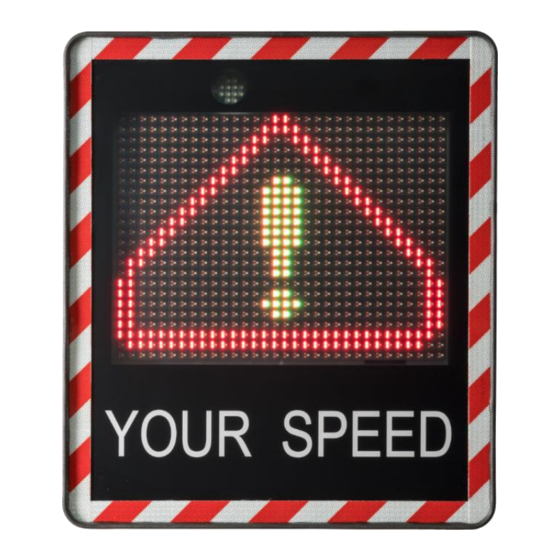
- Page 18 91 & + triangle + DANGER Zone 90 5 - 90 green prudence 91 - 100 orange ralentir 100 - 110 trop vite ! 111 & + triangle + DANGER Table 2: factory setting by speed limit for the I-SAFE 2...
-
Page 19: Customize The Settings
4.3 CUSTOMIZE THE SETTINGS 4.3.1 Prerequisite The I-SAFE communicates with your PC through a USB stick or a Bluetooth® link (option). Before beginning the setting of your speed display, you’ll have to install the Icoms Software and, if needed, the Bluetooth driver. -
Page 20: Screenshot 2: Assistant, Step 2 - Product Setup Choices Using A Usb Key
See further in this document, p. 21 and following, for texts, pictograms and speed thresholds settings. You can create up to 3 custom zones. Once the parameter file(s) saved on your USB key and ready to be uploaded on the I-SAFE, follow these steps: •... -
Page 21: Bluetooth
Screenshot 3: configuring the sign using a USB stick, choose the settings file to edit 4.3.4.1 Setting the clock of the speed sign using a USB stick Setting the clock using a USB stick erases the data from the I-SAFE memory. Please save your data file before setting the clock. -
Page 22: Time Setting When Using A 3G Or 4G Modem With The I-Safe Sign
4.3.4.2 Time setting when using a 3G or 4G modem with the I-SAFE sign When using a 3G or 4G modem with the I-SAFE sign, please note that the modem will set the time of the I-SAFE sign automatically to UTC (Coordinated Universal Time) and synchronize the time regularly. -
Page 23: Screenshot 5: General Parameters
Screenshot 5: general parameters 4.3.4.3.1 Site name The location name can have a maximum of 32 characters. This information will be sent to the I-SAFE together with the display parameters. It will be saved with the data file. If the Bluetooth communication is activated, the software displays the clock of the device, its serial number and battery status. -
Page 24: Colours, Text And Pictograms
4.3.4.4 Colours, text and pictograms 4.3.4.4.1 I-SAFE 1 Screenshot 6: LED settings for the I-SAFE 1 For each speed threshold (1), it is possible to adjust the following parameters: • What will be displayed for each sequence (2): speed (in green, yellow or red), a pictogram or a fine. -
Page 25: Screenshot 7: Pictogram Library For The I-Safe 1
Screenshot 7. Screenshot 7: pictogram library for the I-SAFE 1 Click on the pictogram of your choice and then on “Select” to insert it in your setting. -
Page 26: Screenshot 8: Pictogram Editor For The I-Safe 1
Screenshot 8: pictogram editor for the I-SAFE 1 Each square represents a LED pixel; every click on a square will change the colour according to the sequence “nothing-green-orange-red”. Once the pictogram is modified or created, save it by clicking on Save. You are then redirected to the pictogram library (Screenshot 7), where you can confirm your choice, then on the LED setting screen (Screenshot 6). - Page 27 By clicking the eraser button, the memory of the speed sign holding the measurements will be erased. 9: choose the « custom zone » The I-SAFE can register up to 3 different sets of custom parameters. Select one of the three through this menu.
-
Page 28: Screenshot 9: Led Settings For The I-Safe 2
4.3.4.4.2 I-SAFE 2 Screenshot 9: LED settings for the I-SAFE 2 For each speed threshold (1), it is possible to adjust the next parameters: • The colour of the speed display: green, orange, red or the "No Score" threshold (3 different "No Score"... -
Page 29: Screenshot 10: Text And Pictogram Library For The Unicolor I-Safe 2
To edit the texts or create your own messages, click on the display area or click on the pencil. The text and pictogram library window will then appear, see Screenshot 10 for the unicolor version and Screenshot 11 for the tricolor version of the I-SAFE 2. Screenshot 10: text and pictogram library for the unicolor I-SAFE 2... -
Page 30: Screenshot 11: Sample Text And Pictogram Library For The Tricolor I-Safe 2
IcomSoft will then show the editor, see Screenshot 12. • For the unicolor I-SAFE 2, click on a LED to light it up and click again to erase the pixel. • For the tricolor I-SAFE 2, click on a LED several times to go from green to orange to red to switched off. -
Page 31: Screenshot 12: Text And Pictogram Editor
Screenshot 12: text and pictogram editor To create a new pictogram or text from scratch, click on an empty rectangle as shown in Screenshot 1 and design the text or pictogram to be shown using the editor 3: Flash display For each threshold, you can activate or deactivate the blinking of the LEDs. -
Page 32: Fines
4.3.4.5 Fines The fines feature is the same for both the I-SAFE 1 and the I-SAFE 2. When instead of showing text or a pictogram the user decides to show a fine, with an example shown in Screenshot 9 where between 71 km/h and 110 km/h the “Fine”... -
Page 33: Time Slots
4.3.4.6 Time slots The time slots feature is the same for both the I-SAFE 1 and the I-SAFE 2. In order to enable the Time Slots feature, toggle the switch with the caption “Enable time slots”, see the arrow showing the switch on Screenshot 15. -
Page 34: Screenshot 15: Enabling The Time Slots
Please note that the time zone to be used when using the I-SAFE with a 3G or 4G modem is UTC, see p. 22. If no modem is used, the time zone of the I-SAFE can be set to the current time zone by using... -
Page 35: Screenshot 16: Time Slots Interface
Screenshot 16: time slots interface... -
Page 36: Downloading The Measurement Data
• Insert the USB stick into the USB port. • The I-SAFE writes the data file on the USB stick and the dot next to the "u" flashes. • Do not remove the USB stick while the dot flashes. •... -
Page 37: Modem
Screenshot 17: choosing between setting up the sign and downloading the data For more information about the Bluetooth connection, see further, APPENDIX 3: , p. 51. 5.3 3G MODEM Please refer to APPENDIX 4: 3G modem OPTION, p. 55, and to the modem user’s guide for more information. -
Page 38: Process The Data
WARNING The I-SAFE is not an accurate counting device. Following traffic intensity and the chosen value for the duration of the display, vehicles may be measured and recorded several times. In other circumstances, a vehicle driving at short distance of another one will not be detected. -
Page 39: Analysis Criteria - Filters
Screenshot 19: data analytics interface 6.2 A – NALYSIS CRITERIA FILTERS If you are working by period of time and speed class, various analysis criteria need to be defined. Use the “Filter” section to filter out the unwanted data 6.3 S TATISTICS The tab “Statistics”... -
Page 40: Graph Types
Screenshot 20: statistics pane 6.4 G RAPH TYPES Once the data have been selected and configured, various graphs and tables are available 6.4.1 Speed classes Clicking on the tab “Speed classes” will allow you to define the speed classes of your choice which will then be shown in the graphs. -
Page 41: General Chart
Screenshot 21: defining the speed classes for analysis Screenshot 22: graphical overview of the measurements divided in speed classes 6.4.2 General chart The graph expresses the volume according to time. By checking the boxes located underneath the graph, you can view the change curves for the average speed, the percentile and the percentage excess speed in relation to the pivot value set in the “Speed classes”... -
Page 42: Saving And Exporting Data
Screenshot 23: general chart showing the measured vehicles and statistics 6.5 S AVING AND EXPORTING DATA To export the data, click on the “floppy disk” icon on the top right corner of the application. Screenshot 24: choosing the export format You can save files to the following formats as shown in Screenshot 24: ▪... -
Page 43: Excel Report
.xlsm. Make sure as well that the tab “data” is present in the new template. The IcomSoft I-SAFE will use this « data » tab to insert data. No customized data, formula or graphic may be included in this tab. -
Page 44: General Settings
Screenshot 26: settings window 6.6 G ENERAL SETTINGS To access the general software settings, click on , upper left in the main window: Screenshot 27: opening the settings window The user can choose the language, units, time format and date format as shown on Screenshot 28. -
Page 45: Screenshot 28: Settings Window
Screenshot 28: settings window... -
Page 46: Physical Characteristic
HYSICAL DESCRIPTION 7.1.1 Display Display: I-SAFE 1: Matrix 24 lines 32 columns with red and green LED + white LEDS flash lamp I-SAFE 2: Red and green LEDs 7-segments digits + white LEDs flash Lower display: matrix 16 lines 52 columns amber LEDs... -
Page 47: Additional Information
8.2 L EGAL DECLARATION Icoms Detections herewith declares that the I-SAFE complies with the essential requirements and other conditions of directive 1999/5/EC that apply to it. You can obtain a copy of the "Declaration of Conformity" by sending a request to info@icomsdetections.com. -
Page 48: Appendix 1: Parameters Encoder
9.1 G ENERAL When the I-SAFE is powered on, de encoder display shows o. It means it is in « configuration » mode and ready to communicate through Bluetooth, if the option is available. After 15 seconds, the I-SAFE goes to « measure mode », with the parameters of the TAILOR MADE ZONE 1. - Page 49 Insert the USB stick into the USB port. o The I-SAFE reads the data from the USB stick and the dot next to the "u" flashes. o Do not remove the stick while the dot next to the “u” is flashing.
-
Page 50: Appendix 2: Icomsoft I-Safe Software Installation
RAM: 512 MB Processor Min 1.5 GHz Bluetooth 2.0 Class 1 (100m) PLEASE UNINSTALL ANY BLUESOLEIL DRIVER PREVIOUSLY INSTALLED ON YOUR COMPUTER. IT IS NOT COMPATIBLE WITH THE ICOMSOFT I-SAFE. 10.2 I NSTALLING COMS SOFTWARE 1. Download the software or insert the USB stick into the drive. Double-click on the installation executable “IcomSoft-I-SAFE-2.x.y-setup.exe”... -
Page 51: Appendix 3: Bluetooth Option
I-SAFE and for the module, when the I-SAFE is in “measure” mode, place the parameter encoder (4) on “b”; the I-SAFE comes then back to configuration mode and writes its own serial number in the Bluetooth module. The I-SAFE goes to “measure” mode again after +/- 10 sec. -
Page 52: Connection
Launch the Icoms Software and follow the instructions given by the software: select the type of display to connect to (I-SAFE 1 or I-SAFE 2) and then click on the Bluetooth icon to start scanning the Bluetooth devices in your vicinity, see Screenshot 29. -
Page 53: Screenshot 30: Adding The Bluetooth Device To Your Windows Pc
Screenshot 30: adding the Bluetooth device to your Windows PC Windows asks if you want to pair the device, click “Allow” as shown on Screenshot 31. Screenshot 31: allow Windows to pair with the device Once the pairing successful, Windows will show you that the connection succeeded as shown on Screenshot 32. -
Page 54: Screenshot 32: Bluetooth Connection Success
Screenshot 32: Bluetooth connection success Please note: 1. The quality of the Bluetooth transmission depends of the choice of component, its characteristics, its version and the brand name (Sitecom, Toshiba, … ). 2. Two important properties to check are: → the USB version if an external dongle is being used: minimum 2.0; →... -
Page 55: Appendix 4: 3G Modem Option
12 APPENDIX 4: 3G MODEM OPTION An optional 3G communication module is available for the I-SAFE. It is easy to install it in the service box. Please note it is not possible to use simultaneously a GPRS module and a Bluetooth module. -
Page 56: Settings
2. Connect the power cable and the flat communication cable to the modem and the board as shown in Figure 14, item 2. Figure 14: communication board in the I-SAFE service box connected to the modem 3. Slide the modem inside the housing and place it in the holder: Figure 15: installed modem in the I-SAFE housing 12.3 S... -
Page 57: Appendix 5: Solar Panel Installation
13 APPENDIX 5: SOLAR PANEL INSTALLATION Please first switch the battery on, before connecting the solar panel. 1. Cut the tie-raps to untie the 2 supporting slats and the accessories: 2. Fasten the 2 supporting slats with the provided mounting angles/nuts Pay attention: right and left slats are different 3. - Page 58 4. Fasten the slats on the lower part of the pole bracket with the provided nuts 5. Fasten the central screw on the upper part with the nut: Please first switch the battery on, before connecting the solar panel.
-
Page 59: Appendix 6: Using The Padlock
14 APPENDIX 6: USING THE PADLOCK Use the padlock to secure the I-SAFE by locking the bracket with the fixture on the back of the I-SAFE as shown in Figure 16. Figure 16: using the padlock to secure the I-SAFE...
Need help?
Do you have a question about the I-SAFE and is the answer not in the manual?
Questions and answers