Table of Contents
Advertisement
Quick Links
Advertisement
Table of Contents

Related Manuals for Bridge BriPower ESA Series


Summary of Contents for Bridge BriPower ESA Series
- Page 1 BriPower ESA Series User Manual...
- Page 2 INFO & CONTACT ADDRESSES Bridge Technology is a company focusing on business of power supplies and test systems for new energy applications. We are devoted to providing high quality products and solutions for customers. Bridge Technology has a top-class R&D team in China, workstation on modularization and standardization power supplies and systems.
- Page 3 This manual is based on the technical status at the time of printing. Bridge Technology will make every effort to ensure that the information in this manual is up-to-date and accurate. It will be modified without notice.
-
Page 4: Safety Requirements
To prevent potential hazards, please follow the instructions in the manual to safely use the instrument. Bridge Technology have no liability for failures caused by violate protective measures or other safety regulations. - Page 5 When the module is powered on, do not touch the exposed connectors or components.
- Page 6 Safety Notices and Symbols Safety Symbols PROTECTIVE EARTH SHOCK HAZARD WARNING TERMAINAL Other Symbols IMPORTANT INFORMATION Safety Information WARNING If improperly operated, it may cause injury or danger immediately. WARNING Potentially dangerous situation or practice. If not avoided, it will result in serious injury or death.
-
Page 7: Table Of Contents
Content Safety Requirements ......................... 4 Part I Equipment Introduction....................10 System Overview ..................... 11 1.1.1 Overview of ESA series ..................11 1.1.2 Model Description ................... 11 1.1.3 Features and configuration ................11 1.1.4 General Specification ..................12 Appearance and structure of Equipment ..............14 1.2.1 Appearance and outline .................. - Page 8 Part IV Function and Feature Introduction................48 Grid Simulation Function..................49 Re-generative AC Load (-LD option) ................ 52 Extends to DC output (-DC option) ................53 Line impedance (RL) Simulation (-IMP option) ............53 Part V Software Interface ....................54 GUI Software Introduction ..................
- Page 9 Equipment Repair ....................94 7.2.1 Equipment self-test ....................94 7.2.2 Maintenance service ....................94 7.2.3 Equipment returns ..................94 Part VIII Programming ......................95 Command Format ....................96 8.1.1 Parameters data type ..................96 8.1.2 Command parameters/Return valve units ............96 8.1.3 Command format ....................
-
Page 10: Part I Equipment Introduction
Part I Equipment Introduction 1.1 System Overview 1.1.1 Overview of ESA series 1.1.2 Model description 1.1.3 Features and configuration 1.1.4 General specification 1.2 Appearance and Structure of Equipment 1.2.1 Appearance and outline 1.2.2 Front panel 1.2.3 Rear panel 1.2.4 Internal structure 1.2.5 Control module of front panel 1.2.6 Connection layer and other interface layers 1.3 Interface Description... -
Page 11: System Overview
1.1 System Overview 1.1.1 Overview of ESA series The BriPower ESA series is a high-performance and multi-functional grid simulator, using advanced PWM technology, which contains multiple output power levels from 30kVA to 500kVA and above for single system, and up to 4 individual systems can be paralleled to achieve power levels up to 2MVA. -
Page 12: General Specification
▪ TFT-Touch panel operation ▪ LAN/RS485 interfaces (standard), RS232/Analog control interfaces (optional) ▪ Mod-bus/SCPI protocols ▪ Emergency stop button ▪ Switchable insulation monitoring ▪ Output contactor ▪ Remote sense ▪ CE conformity ▪ Customized voltage, current and power ranges 1.1.4 General Specification Output Input Output Modes... - Page 13 Power Level 30kVA 60kVA 120kVA 250kVA 500kVA Voltage Range 0-300V L-N Output 46A/ph 91A/ph 182A/ph 379A/ph 758A/ph current Dimension 800*800*1900 800*800*2200 2*800*800*2200 2*900*900*2200 4*900*900*2200 (W*D*H mm) Weight <800kg <1000kg <1700kg <2500kg <5000kg *other Power/Voltage Level can be offered. Contact Sales.
-
Page 14: Appearance And Structure Of Equipment
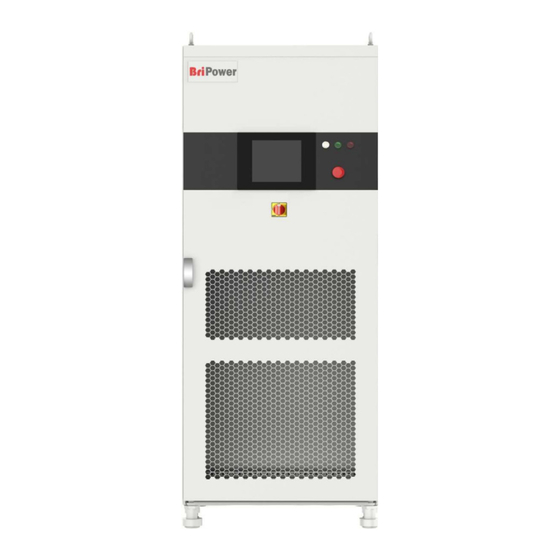
1.2 Appearance and structure of Equipment 1.2.1 Appearance and outline The overall appearance of the ESA (take ESA 30-300-46 as an example) is shown in Figure 1-1. There are lifting rings at the top of the cabinet for lifting operation and moving rollers at the bottom of the cabinet for users to move flexibly. - Page 15 Figure 1-2 Front panel Table 1-1 Number Name Notes ① White Light The power supply is standby. ② Green Light The power supply is operating normally. ③ Red Light The power is failure. Capacitive TFT touch panel displayer (12 inch), using the Windows OS., provides a GUI software, and has the ④...
-
Page 16: Rear Panel
1.2.3 Rear panel The rear panel of ESA series is equipped with RS485/LAN interface (standard), TTL interface(standard) and ATI interface (optional). Figure 1-3 Rear panel Table 1-2 Number Name Note RS485 interface Standard configuration, used for remote control. ① Standard configuration, it is a communication interface, ②... -
Page 17: Internal Structure
1.2.4 Internal structure As shown in Figure 1-4, take ESA 200-300-300 as an example, from top to bottom, the internal modules of ESA series are: ①control box layer, ②module layer, ③other input/output component layer, ④wiring layer and other interface layers. Figure 1-4 Internal structure 1.2.5 Front panel of control module The front panel of ESA series control module is equipped with LAN interface (standard),... -
Page 18: Connection Layer And Other Interface Layers
Figure 1-5 Front panel of control module Table 1-3 Number Number Notes ① LAN interface Standard, for touch screen communication ② LAN interface Standard, for debugging and firmware update ③ For control module heat dissipation ④ Power switch For the power on / off the control module Optional, for communication between power supply. - Page 19 Figure 1-6 connection layer and other interface layers Table 1-4 Number Name Notes ① Wiring copper bar of input side From left to right are PE, N, A, B, C ② Wiring copper bar of output side From left to right are N, A, B, C a + b →...
-
Page 20: Interface Description
1.3 Interface Description 1.3.1 LAN interface(standard) The LAN interface is one of the equipment communication interfaces. 1.3.1.1 Location of LAN interface The two LAN interfaces on front panel of the control module are used for touch panel communication (Figure 1-7①) and hardware debugging (Figure 1-7②). Figure 1-7 front panel of the control module IMPORTANT INFORMATION The LAN interface (Figure 1-7①) is connected to the touch panel by default before... -
Page 21: Rs485 Nterface (Standard)
1.3.1.2 Connection of LAN interface Please refer 5.2 for detail connection method. IMPORTANT INFORMATION The network wire used for LAN connection is Straight-Through Wired Cable. 1.3.1.3 Remote control setting Please refer 5.2. for detailed remote control setting method. 1.3.2 RS485 nterface (standard) The RS485 interface is one of the equipment communication interfaces. -
Page 22: Rs232 Interface (-232 Option)
interference, armored twisted pair shielded cable (ASTP-120Ω 18AWG) (one pair) should also be used. The connection method is shown in Figure 1-10. Figure 1-10 Connect RS485 The port setting information: Port: COM port on control PC Baud Rate: 9600 Data Bits: Stop Bits: Parity: None... - Page 23 Figure 1-13 Front panel of the power supply 1.3.3.2 Connection of RS232 interface The RS232 interface usually appears in the form of 9 pins (DB-9). Two RS232 interfaces (one male and one female) can be used by directly plugging in the interconnect normally. The meaning of the pins is as follows.
-
Page 24: Ttl Interface (Standard)
DTR(Data Terminal Ready) Data Terminal Ready → SG(Signal Ground) Signal Ground Data Set Ready DSR(Data Set Ready) ← RTS(Request To Send) Request To Send → CTS(Clear To Send) Clear To Send ← RI(Ring Indicator) Ring Indicator ← The port setting information: Port: COM port on control PC Baud Rate:... -
Page 25: Ati Interface (-Ati Option)
1.3.4.2 Connection of TTL interface Figure 1-14 TTL interface connection method 1.3.5 ATI Interface (-ATI option) The output voltage of power supply can be controlled via control signals and by using the analog input (ATI interface). ESA series uses BNC connector for this analog input. The set value is adjusted according to the analog input voltage (0-5 V). -
Page 26: External Emergency Stop Interface (Standard)
1.3.5.2 Connection of ATI interface The ATI interface of the ESA series appears as BNC. The connection between the equipment and the signal generator is shown in Figure 1-16. Figure 1-16 ATI interface connection method 1.3.6 External emergency stop interface (standard) ESA series provides an external emergency stop interface, which can be connected to the user's external emergency stop switch. -
Page 27: Remote Sense Interface (Standard)
Figure 1-17 1.3.6.2 Connection of emergency stop interface T he wiring methodof external emergency stop is shown in Figure 1-18. Figure 1-18 Emergency stop interface connection method 1.3.7 Remote sense interface (standard) The remote sense wire is connected to the output terminal of the power supply by the remote sense port. - Page 28 1.3.7.1 Location of remote sense interface The remote sense interface is located at the internal wiring layer-③: e, f, g, h, i, j (Figure 1- 19). Fugure 1-19 1.3.7.2 Connection of remote sense interface The remote sense interface is connected to the output terminal of the ESA power suppLy by default before leaving the factory, as shown in Figure 1-20.
-
Page 29: Master-Slave Interface(-Ms Option
Figure 1-21 Remote sense connection method 1.3.8 Master-slave interface(-MS option) ESA series support parallel connection of power supply of the same power. 1.3.8.1 Location of master-slave interface The master-slave interface is located on the front panel of the power supply control box, as shown in Figure 1-22⑤. - Page 30 1.3.8.2 Connection of master -slave interface When power supplies are connected in parallel, the specific operation steps are as follows. Step 1: Pass the fiber optic cable through the cable hole on the top of the cabinet, as shown in Figure 1-23.
- Page 31 IMPORTANT INFORMATION If the parallel slave is designed without a touch screen, in addition to the optical fiber cable, the parallel communication network cable needs to be inserted through the threading hole on the top of the cabinet, and then connect as shown in Figure 1-25.
-
Page 32: Part Ii Equipment Installation
Part II Equipment Installation Check before Installation 2.1.1 check the packing 2.1.2 check the equipment Equipment Installation 2.2.1 Selection of input/output cables 2.2.2 Installation steps 2.2.3 Add single-phase output (-1P option) 2.3 Parallel installation of equipment... -
Page 33: Check Before Installation
There are no defects that seriously affect the appearance of the product, such as scratches, indentation, color difference, paint drop, etc. IMPORTANT INFORMATION If the product has any mechanical damage, missing parts, fails electrical or mechanical tests, please contact the sales of Bridge Technology. -
Page 34: Equipment Installation
2.2 Equipment Installation 2.2.1 Selection of input/output cables Before the equipment is installed, the user should confirm the model on the nameplate, select the appropriate specifications of the cable and the cold end according to the equipment input/output voltage level and current of the equipment, and crimp the input side cable and the output side cable. - Page 35 Step 2: The input terminal (PE/N/A/B/C) and output terminal (N/A/B/C) of the equipment are shown in Figure 2-4, pass the cable through the inlet hole at the bottom and connect it to the terminal. Figure 2-4 Copper bar CAUTIOUS To avoid electrical hazards, connect the ground terminal to the protective ground terminal before connecting any input or output terminals.
-
Page 36: Add Single-Phase Output (-1P Option)
2.2.3 Add single-phase output (-1P option) ESA series with the -1P option adds a single-phase output function. By changing the wiring method (parallel three-phase output terminals, as shown in Figure 2-6), the output current can be increased to three times the single-phase current. Figure 2-6 Increase single-phase output wiring diagram... -
Page 37: Parallel Installation Of Equipment
2.3 Parallel installation of equipment ESA series support parallel connection of power supply of the same power.the specific operation steps are as follows. Step 1: Pass the fiber optic cable through the cable hole on the top of the cabinet, as shown in Figure 2-7. - Page 38 IMPORTANT INFORMATION If the parallel slave is designed without a touch screen, in addition to the optical fiber cable, the parallel communication network cable needs to be inserted through the threading hole on the top of the cabinet, and then connect as shown in Figure 2-9.
- Page 39 Step 4: As shown in Figure 2-11, connect the input and output cables of the two equipment in parallel. Figure 2-11 Wiring diagram between parallel cabinets Step 5: After completing the above parallel work, complete the remaining wiring according to 2.2.2.
-
Page 40: Part Iii Power-On Operation
Part III Power-on Operation 3.1 Power-on Operation 3.2 GUI Software Operation (Local Control) 3.3 GUI Software Operation (Remote Control) 3.4 Power-off Operation... -
Page 41: Power-On Operation
3.1 Power-on Operation Step 1: Power on the AC input side After completing the installation, close the circuit breaker on the distribution side (Figure 3- 1①). Figure 3-1 Equipment and the circuit breaker CAUTIOUS To prevent any damage to the equipment, make sure to confirm the correct wiring sequence. - Page 42 Step 3: Turn on power knob Turn clockwise to close the control switch on front panel (figure 3-3⑤) after closing the cabinet door, the power supply is standby. If the power supply communication connection is normal, the white light is always on (figure 3-3①). Figure 3-3 Front Panel...
-
Page 43: Gui Software Operation (Local Control)
3.2 GUI Software Operation (Local Control) ESA series provide GUI software, it is installed in the touch panel, which uses Windows OS. (the software can also be installed on the control PC connected to the power supply). A few seconds after the power is initialized, the control unit and touch screen work, the power supply is standby. - Page 44 - Capture, display and save output voltage and current Waveforms. - Display power source faults The specific functions of the software will be introduced in Part V.
-
Page 45: Gui Software Operation
3.3 GUI Software Operation(Remote Control) ESA series provides GUI software, which can be installed on the control PC connected to the power supply. The detailed operation information is in Part V. -
Page 46: Power Off Operation
3.4 Power off Operation Step 1: Close the GUI software on the TFT-Touch panel /PC and shut down. Step 2: Turn the power knob counterclockwise (Figure 3-9⑤). Figure 3-9 Front panel Step 3: Open the cabinet door and power off the control unit switch (Figure 3-10④). Figure 3-10 Front panel of control module IMPORTANT INFORMATION Closing the switch on the front panel of the control box at the first time. - Page 47 Step 4: Power off circuit breaker of the AC input side (Figure 3-11①). Figure 3-11...
-
Page 48: Part Iv Function And Feature Introduction
Part IV Function and Feature Introduction Grid Simulation Function 4.1.1 Low/zero voltage ride through test 4.1.2 three-phase unbalance, harmonics, and inter-harmonics 4.1.3 harmonics and inter-harmonics Re-generative AC Load (LD option) Extends to DC output (DC option) Line impedance (RL) Simulation (IMP option) -
Page 49: Grid Simulation Function
4.1 Grid Simulation Function ESA series can be used as a grid simulator to meet the requirements of grid tied DG regulations testing, such as: grid voltage abnormality test, grid frequency abnormality test, low/zero voltage ride through test, anti-islanding test, etc. ESA series have Various simulation functions, including voltage and frequency fluctuations, voltage sags, low/zero voltage ride through, three-phase unbalance, harmonics and inter-harmonics. - Page 50 Voltage drop simulation (LVRT for inverter test) ESA series provide firmware and software support for low/zero voltage ride through test for PV inverters. ESA is used to simulate grid voltage/frequency changes, drops and sags to meet the low voltage ride through test requirements of PV inverters. Figure 4-5 Voltage drop Figure 4-6 Zero voltage ride In the sequence mode, there is a TTL trigger signal output when voltage or frequency changes.
- Page 51 ESA series can also capture, display, and save the output voltage and current Waveforms and store them inside the power supply for retrieval and analysis by users. Figure 4-10 Waveform browsing panel The output terminal of ESA series can be short-circuited and supports short-circuit test. According to the technical specifications of photovoltaic power generation grid-connected inverters, the photovoltaic inverter must have a short-circuit protection function.
-
Page 52: Re-Generative Ac Load (-Ld Option)
Re-generative AC Load (-LD option) ESA series with -LD option can be used as regenerative AC electronic load. This function consists of CR mode, Rectifier mode, CC/CP phase lead/lag mode. CR mode is used to simulate three-phase resistive loads, the CR mode and three-phase resistance parameters can be set through the panel to simulate the resistance sequence. -
Page 53: Extends To Dc Output (-Dc Option)
4.3 Extends to DC output (-DC option) In source and sink mode, ESA series can also be DC output, the frequency range will be DC~100Hz. The DC voltage range is 420V (std), and accuracy is 0.2%FS. The output mode can be AC/DC//AC+DC. -
Page 54: Part V Software Interface
Part V Software Interface 5.1 GUI Software Introduction 5.1.1 Operating status 5.1.2 Sequence mode 5.1.3 Input/output controls 5.2 Communication Setting 5.3 Hardware Limits 5.4 Sequence Mode 5.5 Analog Input 5.6 AC+DC/AC/DC 5.6.1 5.6.2 AC+DC 5.6.3 5.7 Harmonic and inter-harmonic simulation 5.7.1 Harmonic simulation 5.7.2... - Page 55 5.10.1 Real-time Waveform browsing 5.10.2 Historical Waveform browsing 5.11 System Status 5.12 Administrator Account 5.13 Waveform reproduction function...
-
Page 56: Gui Software Introduction
5.1 GUI Software Introduction 5.1.1 Operating status ESA series provides GUI software, which is installed on the front touch screen using the Windows OS. (the software can also be installed on the control PC connected to the power supply). A few seconds after the power supply is initialized, the control unit and touch screen work, the power supply is standby. -
Page 57: Sequence Mode
The red light indicates the equipment automatically stops working ② Fault when a fault occurs during operation. If the equipment runs in normal, the light is dark green. When equipment is operating normally and output AC/DC, the ③ Output green light is always on. When the equipment has no output, the light is dark green. -
Page 58: Input/Output Controls
Manual setting of parameters in sequence -SEQ Parameter mode. ② Input Mode Analog input via ATI interface (-ATI option). -ATI AC output mode. Output DC output mode. ③ Mode AC + DC AC+DC output mode (-DC option). IMPORTANT INFORMATION Output mode-DC mode is only valid after the user selects -DC option, otherwise the setting is invalid. - Page 59 It is used for the output side on/ off, the button is green while outputting, and the green indicator of "Output" is Output On always on (Figure 5-1③). When there is no output, the button becomes red. Used to control the AC output contactor, the output terminal Output Switch of the power supply is live after closing...
-
Page 60: Communication Setting
5.2 Communication Setting Before establishing a network connection between the power supply and the remote workstation/PC, make sure that the remote workstation/PC and the power supply are on the same network segment. The default network address of the power supply is 192.168.1.2, the port is 502, and the default gateway is 255.255. - Page 61 In general, the hardware of workstation/PC connecting to the power supply must follow the requirements: Processor: Intel core 2 duo or above RAM:2GB or above Operating System:Windows 7 or above 10/100/1000 Mbps network port adaptor Network Switch (LAN users) ...
-
Page 62: Hardware Limits
5.3 Hardware Limits To operate safety, please set the relevant protection parameters before the formal test. Operation steps: Click "Hardware Limits" to enter the panel (Figure 5-7). After setting the parameters, click "Apply". Figure 5-7 Hardware limits panel Table 5-4 Number Name Note External emergency stop check box, the external... - Page 63 Three-phase parallel output (-1P option), the three- ④ Three-phase Parallel (Phase A) phase parallel output is valid after checking. Overcurrent protection value, when the output ⑤ OCP (Max~120%) current exceeds the value, the power output will be off. Overvoltage protection value, when the output ⑥...
-
Page 64: Sequence
5.4 Sequence The output parameters of ESA series power supply can be controlled through GUI software. The sequence mode interface supports a variety of parameter settings, including output phase voltage/phase current, phase angle, frequency, on/off phase angle, dwell time, and switching time. - Page 65 The user can set the on/off phase angle of a phase of each step. Parameter ③ The power system refers to the dwell time firstly by default, and setting 2 then refers to the on/off phase angle. IMPORTANT INFORMATION When the power supply is working, if the parameters need to be modified, please directly click the Keyboard button to modify the parameters, and finally click Apply (no need to turn off the power).
-
Page 66: Analog Input
5.5 Analog Input The output voltage of ESA series can be controlled by control signal and using analog input (ATI interface). The ATI interface is located on the rear panel of power supply, please refer to 1.3.5 for specific connection. The BNC connectors for analog input is used in ESA series. The set value will be adjusted according to the AC/DC voltage (0-5 V) of the analog input. -
Page 67: Ac/Ac+Dc/Dc
5.6 AC/AC+DC/DC ESA series adopts bidirectional design and can be used as AC/DC power supply for DUT. The output modes include: AC, DC, AC+DC. Figure 5-13 Output mode 5.6.1 AC The ESA series allows the generation of AC voltage, current which can simulate the real AC circuit conditions. -
Page 68: Ac+Dc
IMPORTANT INFORMATION In AC output mode, the three phases are independently programmable. If the -1P option is added, the output AC current range will be expanded. For example, in ESA 30-300-46 , the standard output AC current is 46A/phase. If the -1P option is added (Add single phase output function), after changing the corresponding wiring, the maximum single-phase AC current can be output 138A. -
Page 69: Dc (-Dc Option)
IMPORTANT INFORMATION When the CV mode is selected, the parameters that can be set to AC voltage and DC offset voltage. when the CC mode is selected, the parameters can be set to AC current and DC offset current. 5.6.3 DC (-DC option) In source and sink mode, ESA can also be designed as a DC output, allowing DC voltage and current to be generated. -
Page 70: Harmonic And Inter-Harmonic Simulation
5.7 Harmonic and inter-harmonic simulation 5.7.1 Harmonic simulation ESA series provides GUI software, which can edit up to the 50th harmonic. Test steps: Click "Sequence Mode" to enter the panel, firstly set the operating parameters (such as output voltage, frequency). Click "Apply"→"Power On"→"Output On", the power supply is on. Check the harmonic selection box (Figure 5-15①), click the A/B/C phase harmonic simulation button (Figure 5-15③), the harmonic setting panel of each order will automatically pop up, then the user can set the harmonic angle, content and other parameters. -
Page 71: Inter-Harmonic Simulation
Table 5-7 Number Name Note Harmonic ① After checking, the harmonic setting is valid. selection box After checking, the three-phase harmonics can be set at the ② Coupling box same time. If unchecked, three-phase harmonics can be set independently. Three-phase harmonic setting button, the panel is shown A/B/C phase in Figure 5-16 will automatically pop up after clicking it. - Page 72 button (Figure 5-17②), the inter-harmonic setting panel will automatically pop up (Figure 5- 18). The user can set the inter-harmonic frequency, angle, content, and other parameters on this panel. After the parameter setting is completed, check the corresponding box, and click "Setting"...
-
Page 73: Simulation Of Re-Generative Ac Load
5.8 Simulation of Re-generative AC Load ESA series with -LD option can be used as regenerative AC electronic load. This function consists of CR mode, Rectifier mode, CC/CP phase lead/lag mode. 5.8.1 CR mode CR mode is used to simulate three-phase resistive loads, the CR mode and three-phase resistance parameters can be set through the panel. -
Page 74: Rectifier Mode
5.8.2 Rectifier mode Rectifier mode is mainly used to simulate nonlinear Rectifier load testing. Users can set parameters such as CC/CR mode, load current/power value and CF value (setting range 1.414~3) through the panel. Test steps: Click "Sequence" to enter the panel, select the CC/CP mode on the right side of the panel and set the three-phase current/power parameters and CF parameter values (Figure 5-20), then click "Apply"→"Power On"→"... -
Page 75: Cc/Cp Phase Lead/Lag Mode
5.8.3 CC/CP phase lead/lag mode When the CC/CP phase lead/lag mode simulates sinusoidal current, the user can set the CC/CP mode through the panel to adjust the load current or power, and the phase angle range can be adjusted from 90° to -90°, which simulates inductive and capacitive loads Voltage and current conditions. -
Page 76: Measurements
5.9 Measurements The GUI software of ESA series can monitor the input/output status of the equipment in real time. Click "Measurement" to enter the panel. The user can monitor real-time Input current/voltage/power (Figure 5-22), output current/voltage/power, output frequency and other parameters on this panel (Figure 5-23). Figure 5-22 Measurements panel-Input Figure 5-23 Measurements panel-Output... -
Page 77: Waveform
5.10 Waveform 5.10.1 Real-time waveform browsing The GUI software of ESA Series can record the waveform of output voltage and current, and store in the TFT touch panel/workstation, for the user to retrieve browsing and analysis in future. Steps: Click "waveform" to enter the panel (Figure 5-24). In the window of waveform browsing, the user can individually or simultaneously select the data of output voltage or output current (Figure 5-24⑦) and browse the waveform. -
Page 78: Historical Waveform Browsing
Table 5-8 Number Name Note ① Zoom In Click “Zoom in” control to zoom in waveform. Click “Restore” control to restore the enlarged waveform to the ② Restore default scale for browsing. Retrieve the historical Waveform data, click it to pop up the ③... - Page 79 Figure 5-25 Historical waveform panel...
-
Page 80: System Status
5.11 System Status The user can browse the status of each part of the system during the testing through the GUI software. Operation steps: Click "System Status" to enter the panel, users can browse equipment faults and status (Figure 5-26), software faults and status (Figure 5-27). Green light means no fault, and red light means fault occurs. -
Page 81: Administrator Account
5.12 Administrator Account After entering the administrator account, the internal parameters can be set. It is not recommended that the user enter the account to avoid accidental settings causing equipment failure or loss of accuracy. The default login account is a guest account, and all functions of the power supply are open and can be used normally. -
Page 82: Part Vi Equipment Verification And Calibration
Part VI Equipment verification and calibration Performance Verification 6.1.1 Verify equipment and settings 6.1.2 Verify content Voltage Range Current Range Frequency Range Voltage Accuracy Current Accuracy Frequency Accuracy Power Accuracy Output Characteristics Load Regulation Voltage THD Ripple Test Harmonic Test Inter-harmonic Test Electronic load test Voltage drop Change... -
Page 83: Performance Verification
6.1 Performance Verification 6.1 1 Verity equipment and settings Figure 6-1 Three-phase output test with resistive load Figure 6-2 Single-phase output test with resistive load Figure 6-3 Load step change test... - Page 84 Figure 6-4 Recycling electronic load test Table 6-1 Instruments Model Power analyzer ZIMMER LMG670 Oscilloscope Tektronix DPO2002B/ DS4000E Voltage Probe RIGOL RP1050D Current Probe CAT Ⅲ 600V/1000A Noise Detector SOUND LEVEL METER Temperature Scanner FLUKE MT4 MAX breaker Schneider C4A AC contactor CHNT NC2-150 CAUTIOUS...
-
Page 85: Verity Content
6.1.2 Verity content • Voltage Range Connect the input side of the AC/DC source to the power grid, so that the input voltage is within the operating voltage range of the power supply, and the output side is connected to a pure resistive load. - Page 86 • Current Accuracy Connect the input side of the AC/DC source to the power grid, so that the input voltage is within the operating voltage range of the power supply, and the output side is connected to a pure resistive load. Set the output voltage value to make the power supply work within the rated output current range, read and record the output current measurement value on the power analyzer and the power supply, and take the largest error for calculation.
- Page 87 the power analyzer and the power supply, and take the largest error for calculation. The power accuracy is obtained by the following formula: | �� − �� | �� = × 100% �� And: ——Power Accuracy; �� �� ——Power value measured via power analyzer, kW; ��...
- Page 88 the rated output voltage range, read and record the output voltage measurement value on the power analyzer when there is no-load and On-load, and set the frequency value as:50Hz/1000Hz/2000Hz. Read and record the various voltage THD on the power analysis. •...
- Page 89 voltage is within the operating voltage range of the power supply. The AC load function consists of CC&CP Rectifier mode, CC&CP lead/lag mode, and CR mode. Set parameter values such as CC/CP mode, CF and phase angle on the panel (the phase angle setting range is 90°~-90°, the CF parameter setting range is 1.414~3), read and record the oscilloscope waveform.
- Page 90 within the rated output voltage range, read and record the offset measurement values on the power analyzer and the power supply. • TTL Signal Trigger Connect the input side of the AC/DC source to the power grid, so that the input voltage is within the operating voltage range of the power supply.
-
Page 91: Test Record Form
• LCD Display Test In the setting and running state, there is no flicker and flower on LCD screen. • Noise test • Temperature test 6.2 Test Record Form Please refer to the ESA test report. -
Page 92: Part Vii Equipment Maintenance And Repair
Part VII Equipment Maintenance and Repair Equipment Maintenance 7.1.1 Equipment operating environment 7.1.2 Equipment maintenance Equipment Repair 7.2.1 Equipment self-test 7.2.2 Maintenance service 7.2.3 Equipment return... -
Page 93: Equipment Maintenance
7.1 Equipment Maintenance Please be careful of the maintenance environment of equipment. Bridge Technology has no liability for failures caused by breaking equipment rules. 7.1.1 Equipment operating environment • The equipment is used indoors, and the operating temperature is not higher than 40 ° C and not lower than 0 °... -
Page 94: Equipment Repair
Bridge Technology. Bridge Technology has no liability for equipment failure caused by self-assembly. 7.2.2 Maintenance service If the purchased equipment failure during the warranty period, Bridge Technology will repair the equipment according to the specific information provided by the customer. Contact information is on Page 05. 7.2.3 Equipment returns If the failure is confirmed by itself rather than the connection problem, please return the power supply to Bridge Technology to repair. -
Page 95: Part Viii Programming
Part VIII Programming Command Format 8.1.1 Parameters data type 8.s1.2 Command parameters/Return value units 8.1.3 Command format Command Sets 8.2.1 Common commands 8.2.2 SCPI and panel comparison 8.3 Example... -
Page 96: Command Format
8.1 Command Format The parameter data types, parameters and the value range and formats of the programmed commands of the power supply are introduced in this Part. The user shall carefully read the content of the following Parts before developing the control operations. 8.1.1 Parameters data type Parameters Data Type Effective Parameters <boolean>... -
Page 97: Command Sets
8.2 Command Sets 8.2.1 Common commands Commands Return Value Description Return: ESA-***-*** Return the information of *IDN Firmware Version 1.0 equipment *RST None Fault Rest Inquire status Remote/Local. It will return 1 if Remote? Remote,1/0 working in Remote mode, else return 0. - Page 98 Inquire the value of Output OPC? OLP <,NRf> Peak Current Limit Set the value of DC Offset DOVC <NRf> None Voltage climbing Inquire the value of DC Offset DOVC? DOVC <,NRf> Voltage climbing Set the value of DC Offset DOCC <NRf> None Current climbing Inquire the value of DC Offset...
- Page 99 SET:AMPB <NRf> None Set the value of amplitude of B SET:PHASEC <NRf> None Set the value of phase of C SET:AMPC <NRf> None Set the value of amplitude of C SET:FREQ? SET: FREQ<,NRf> Inquire the value of frequency SET:PHASEA? SET: PHASEA<,NRf> Inquire the value of phase of A Inquire the value of amplitude SET: AMPA?
- Page 100 OFFSET:B? OFFSET:B<NRf> Inquire the dc offset of B OFFSET:C? OFFSET:C <NRf> Inquire the dc offset of C OFFSET OFFSET? Inquire the dc offset of A~C <NRf1><,NRf2><,NRf3> Validate the offset parameters OFFSET APPLY None that have been set. Measure the voltage of output VOLT:A? VOLT:A<NRf>...
-
Page 101: Scpi And Panel Comparison
Measure the dc current of CURDC:C? CURDC:C<NRf> output C CRUDC Measure the dc current of CURDC? <NRf1><,NRf2><,NRf3> output A~C Inquire frequency FREQ:A? FREQ:A<NRf> output A Inquire frequency FREQ:B? FREQ:B<NRf> output B Inquire frequency FREQ:C? FREQ:C<NRf> output C FREQ<NRf1><,NRf2><,NRf3 Inquire frequency FREQ? >... - Page 102 OPC <NRf> None Set Output Peak Current Limit Set the value of DC Offset Voltage DOVC <NRf> None climbing Set the value of DC Offset Current DOCC <NRf> None climbing Inquire the value of DC Offset Voltage DOVC? DOVC <,NRf> climbing Inquire the value of DC Offset Current DOCC?
- Page 103 (Sequence) Figure 8-2 Commands Return Value Description POWER ON/OFF None Turn ON/OFF the switch of grid side. Enable/Disable the output of power OUTPUT ON/OFF None supply Return status of switch of grid side POWER:STAT? POWER:STAT,1/0 1:ON 0:OFF Return status of output of power supply OUTPUT:STAT? OUTPUT:STAT,1/0 1:ON...
- Page 104 Set output frequency inactivated step in SEQ:FREQ <NRf> None sequence mode Set the phase of output A in activated SEQ:PHASEA <NRf> None step in sequence mode Set the amplitude of output A in SEQ: AMPA <NRf> None activated step in sequence mode Set the phase of output B in activated SEQ:PHASEB <NRf>...
- Page 105 Inquire the amplitude of output B in SEQ:AMPB? SEQ: AMPB<,NRf> activated step in sequence mode Inquire the phase of output C have been SEQ:PHASEC? SEQ: PHASEC<,NRf> set inactivated step in sequence mode Inquire the amplitude of output C in SEQ:AMPC? SEQ: AMPC<,NRf>...
- Page 106 Second : LAB; duration; switch time; output frequency ; the phase of output A; the amplitude of output A; the phase of output B; the amplitude of output B; the phase of output C; the amplitude of output C; the condition value; the selectioncondtion;...
- Page 107 3. (Harmonic Setting) Figure 8-3 Commands Return Value Description Set second harmonic parameters: Harmonic order; HARM phase of a; <NRf1><,NRf2><,NRf ratio of a; 3><, None phase of b; NRf4><,NRf5><,NRf6 ratio of b; ><, NRf7> phase of c; ratio of c; Inquire 2-40 harmonic parameters:...
- Page 108 1. (Inter Harmonic Setting) Figure 8-4 Commands Return Value Description Set inter harmonic parameters of Channel Channel; IHARM <NRf1><, NRf2><, Frequency; NRf3><, phase of a; None NRf4><,NRf5><, ratio of a; NRf6><, NRf7> , phase of b; NRf8> ratio of b; phase of c;...
- Page 109 Frequency; phase of a; ratio of a; phase of b; ratio of b; phase of c; ratio of c; Validate the parameters that have been IHARM APPLY None IHARM CLEAR None Clear the Inter harmonics parameters...
-
Page 110: Example
8.3 Example 1) Query information *IDN ESA-AC***-*** Firmware Versioin 1.0 Remote? 2) Set the protection value OVP 300 OVP? OVP300.00 OCP 225 OCP? OCP225.00 3) Set hardware limits LIMIT:CUR 200 LIMIT:CUR? LIMIT:CUR200.00 4) Check for faults FAULT? FAULT0 //No faults FAULT? FAULT1 //Got a fault... - Page 111 SET:PHASEC -240 SET:AMPC 220 SET? SET50.00,0.00,220.00,-120.00,220.00,-240,220 SET APPLY POWER ON POWER:STAT? POWER:STAT1 OUTPUT ON OUTPUT:STAT? OUTPUT:STAT1 VOLT:A? VOLT:A 220.00 CUR:A? CUR:A10.00 POW:A? POW:A 2.20 7) Power up in sequence mode SEQ:LAB? SEQ:LAB1 SEQ:FREQ 50 SEQ:PHASEA 0 SEQ:AMPA 220 SEQ:PHASEB -120 SEQ:AMPB 220 SEQ:PHASEC -240 SEQ:AMPC 220...
- Page 112 SEQ:LAB? SEQ:LAB2 SEQ:FREQ 50 SEQ:PHASEA 0 SEQ:AMPA100 SEQ:PHASEB -120 SEQ:AMPB 100 SEQ:PHASEC -240 SEQ:AMPC 100 SEQ:SWT 100 SEQ:DUT 100 SEQ:CONDSEL NONE SEQ:CONDVAL 0 SEQ:OUTPUT ON SEQ? SEQ2.00,100.00,100.00,50.00,0.00,100.00,-120.00,100.00,- 240.00,100.00,0.00,0.00,1.00 SEQ:APPLY POWER ON POWER:STAT? POWER:STAT1 OUTPUT ON OUTPUT:STAT? OUTPUT:STAT1 VOLT? VOLT*.*,*.*,*.* CUR? CUR*.*,*.*,*.* POW? POW*.*,*.*,*.*...
Need help?
Do you have a question about the BriPower ESA Series and is the answer not in the manual?
Questions and answers