
Related Manuals for Bridge BriPower ESA Series


Summary of Contents for Bridge BriPower ESA Series
- Page 1 User manual of ESA Series Power Supply Product features might be changed by software upgrade. Please acquire the latest version of the manual from our website or contact technical support.
- Page 2 About Bridge Technology Bridge Technology is a company focusing on business of power supplies and test systems for new energy applications. We are devoted to providing high quality products and solutions for customers. Bridge Technology has a top-class R&D team in China, works on modularization and standardization power supplies and systems.
- Page 3 Summary of Safety Requirement Please review the following safety precautions carefully before putting the equipment into operation to avoid any personal injury or damage to the equipment and any product connected to it. To prevent potential hazards, please follow the instructions specified in this manual to use the instrument properly.
- Page 4 Safety Notices and Symbols Safety Notices in this Manual: WARNING Indicates a potentially hazardous situation or practice which, if not avoided, will result in serious injury or death. CAUTION Indicates a potentially hazardous situation or practice which, if not avoided, could result in damage to the product or loss of important data.
- Page 5 This operating manual is based on the state of technology at the time of printing. However, it is possible that despite regular control and correction, the present document contains printing errors or deficiencies. Nanjing Bridge New Energy Technology Co.,Ltd assumes no liability for any technical, printing or translational errors within this manual.
- Page 6 MAINS OPERATION Make sure to verify the model number and voltage stated on the nameplate. Damages due to wrong power feed are not covered by guarantee conditions. CAUTION The unit must only be operated when connected directly to the mains. To avoid damage, do not connect the unit to isolating transformers, autotransformers, magnetic current limiters or similar devices.
- Page 7 ESA Series Overview Main Features ➢ Single system from 30kVA to 500kVA and parallel up to 4MVA and above ➢ Independent three-phase output ➢ Voltage and frequency sequencing programming via GUI, slew rate can be programmed ➢ ON and OFF output phase angle can be programmed ➢...
- Page 8 Document Overview Chapter 1 Quick Start Introduce the appearance, front panel, rear panel user interface as well as internal structure of power source. In addition, it provides the detailed procedures of power connection, power-on/off inspection. Chapter 2 GUI Control Software Introduce the function and operation method of product’s control software in detail.
-
Page 9: Table Of Contents
Contents Chapter 1 Quick Start ....................10 1.1 General Inspection ....................11 1.1.1 Inspect the packing ..................11 1.1.2 Inspect the product ..................11 1.1.3 Check the accessories ................11 1.2 Appearance and outline ..................11 1.3 Front Panel ......................12 1.3.1 LCD ...................... -
Page 10: Chapter 1 Quick Start
Chapter 1 Quick Start The contents of this chapter are as follows: 1.1 General Inspection 1.2 Appearance and Outline 1.3 Front Panel 1.4 Rear Panel 1.5 Internal Structure 1.6 Connect to Power 1.7 Power-on/off Inspection ... -
Page 11: General Inspection
1.1 General Inspection 1.1.1 Inspect the packing If the packaging has been damaged, do not dispose the damaged packaging or cushioning materials until the shipment has been checked for completeness and has passed both electrical and mechanical inspection. The consigner or carrier shall be liable for the damage to the product resulting from shipment. -
Page 12: Front Panel
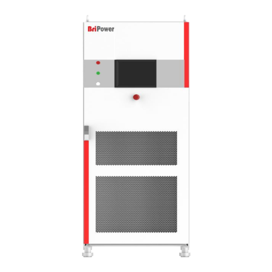
Figure1-1 Appearance of the equipment 1.3 Front Panel This section introduces the front panel of ESA series power source. The differences of models are introduced separately. Firgure1-2 Front panel of ESA series 1.3.1 LCD 10 inches TFT display. It is used to display the system parameter setting, system output state, menu items, prompt messages, etc. -
Page 13: Indicator Of Status
1.3.2 Indicator of Status Lights indicate the working state of the power source in a concise manner. It includes indicator of standby mode, indicator of running and fault indicator. There is a system error. Green System is running normally. White System is standby. -
Page 14: Internal Structure
1.5 Internal Structure As shown in Figure 1-4, the left cabinet consists of control module, input circuit breaker, capacitor output filter, pre-charging resistor and transformer; the right cabinet consists of power module and output reactor components, etc. Firgure1-4 Internal Structure Firgure1-5 Control Module This interface is a communication interface used for remote control Debug... -
Page 15: Connect To Power
1.6 Connect to Power ESA series power source supports the world grid standards, but a particular product supports the GRID SYSTEM only for one country or region. Before the power supply is used, it is necessary to verify that the product specifications are consistent with the Local GRID. - Page 16 positive and negative poles on the DC side into the cabinet through the threading holes at the bottom of the cabinet (marked in red in Figure 1-6), and reliably connect with the terminal/wire copper bar. Warning For safety reasons, the grounding protection PE must be connected reliably.
-
Page 17: Power On Inspection
ensure that the phase sequence is correct, the connection is reliable, and the identification is clear to facilitate maintenance and repair in the future. Warning Before connecting the cable, make sure that the upper switch is in the off state. Live work is strictly prohibited. At the same time, ensure that a reliable protective grounding has been made. - Page 18 Figure1-9 Connection of Mains and DUT Figure 1-10 Power on the Control module www.bripower.cn 配电网...
-
Page 19: User Interface
1.8 User Interface The GUI software is installed in the touch panel, which is in fact a computer with Microsoft Windows. The software can also be installed in control PC connected to power supply. The GUI software provides functions including output settings, island test settings, protection parameter settings, waveform display, measurement display and faults display. -
Page 20: Chapter 2 Control Software
Chapter 2 Control Software The contents of this chapter are as follows: 2.1 Setting 2.2 Comprehensive Test 2.3 Island Test 2.4 Measurement Parameter Monitoring 2.5 Wave Monitoring 2.6 Fault Monitoring www.bripower.cn... -
Page 21: Setting
2.1 Setting 2.1.1 Communication parameters Ensure the remote workstation/PC and the power source are in the same network segment before connection. Default IP address: 192.168.1.2, port: 502, default gateway: 255.255.255.0. The IP address of the remote workstation/PC shall not be the same as that of the power source. -
Page 22: Protection Parameters
In general, the workstation or PC connecting to the power source hardware must comply with the following requirements: ➢ Processor: Intel Core 2 Duo or above ➢ RAM: 2GB or above ➢ Operating System: Windows 7 or above ➢ 10/100/1000 Mbps network port adaptor ➢... -
Page 23: Line Impedance Parameters
If checked, the external compensation is valid. Be sure to External Compensation connect the compensation terminal to the equipment under text after checking. Inner Closed-loop Open the inner closed-loop. Set the upper limit protection value of the output current. Upper Limit of Current When the output current exceeds this limit, a protection action occurs and the output circuit or input is cut off. -
Page 24: Administrator Account
2.1.4 Administrator account After the software logins the administrator account, the internal parameters of the equipment can be set. It is not recommended that the user login the account to avoid accidental setting and cause equipment fault or loss of precision. - Page 25 Figure 2-7 Comprehensive test interface User can setting the harmonic by clicking the button of ‘Harmonic’ shown as Figure 2-8. Default values of “Harmonic set” are 0. Harmonic in percentage, start phase angle can be set. Only selected harmonic settings will be calculated.
-
Page 26: Island Test
2.3 Island Test It is a test mode set up for the island test according to IEC62116-2008. The user should be familiar with the relevant content of IEC62116 before conducting this test. The test interface is shown in Figure 2-9. Figure 2-9 Island test interface Figure 2-10 Working mode display area Figure 2-10 shows the working mode display area of the software and the... -
Page 27: Measurement Parameter Monitoring
The upper part of the interface displays the current output voltage, current and power of the equipment in real time, as shown in Figure 2-11. Figure 2-11 Island test real-time parameter display ESA series with RLC option can be used as AC load for anti-islanding test (IEC62116-2008). - Page 28 parameters of the equipment. Most of this part of the parameters are displayed in the regular test interface or startup interface. Figure 2-13 Measurement interface The module measurement parameters include the current output of each module, the DC bus voltage and the real-time monitoring temperature of the IGBT.
-
Page 29: Wave Monitoring
2.5 Wave Monitoring The GUI software has a waveform recording function. When the user selects the “Save”, the output voltage and current will be recorded and stored in the storage space of the touch screen/workstation. The user can later retrieve the output waveform for browsing and analysis (as shown in Figure 2-17). -
Page 30: Fault Monitoring
Figure 2-18 Waveform browsing interface toolbar The historical waveform browsing window is shown in Figure 2-19. Click “Read Wave”, the historical waveform will be displayed in the left window, arranged in the order of recording time, and the user can browse one of the waveforms. Similar to the waveform browsing window, the user can also read the value of a point on the waveform or the time interval between two points by the cursors "Cursor1"... - Page 31 hardware fault and status of the equipment. After troubleshooting, the user can reset the equipment by "Reset" to clear the fault. Figure 2-21 Fault browsing interface Status and faults are mainly included in Figure 2-22. Figure 2-22 Status and Fault interface www.bripower.cn...
-
Page 32: Chapter 3 Remote Control
Chapter 3 Remote Control The contents of this chapter are as follows: 3.1 Computer Setting 3.2 Software Setting 3.3 Remote Control www.bripower.cn... -
Page 33: Computer Setting
3.1 Computer Setting The remote-control software uses LAN interface to communicate with the power supply. Before launching the remote-control software, network configuration of computer that remote-control software is running should be configured as following table. IP Address 192.168.1.2 Subnet Mask 255.255.255.0 STAP A: Before the control software is installed on the remote computer, please... -
Page 34: Software Setting
3.2 Software Setting And the default network configuration of power supply is shown in table below. Network configuration can be activated in ‘communication’ option of ‘configuration’ menu. However, it is not recommended to change the default configuration. The network configuration page is shown as Figure 3-1. IP Adress 192.168.1.2 Port... -
Page 35: Appendix A - Specification Of Esa Series
Appendix A — Specification of ESA Series General Specification Output Modes 30kVA – 500kVA in single controller. 4MVA max power Power Level available. Power Level can be customized. Voltage Ranges 0-300V L-N (std), voltage can be customized. Load Regulation 0.2%FS Line Regulation 0.1%FS <1% (Resistive Load) - Page 36 Standard Models Specification Power Level* 30kVA 60kVA 120kVA 250kVA 500kVA Voltage Range* 0-300V L-N Output current** 46A/ph 91A/ph 182A/ph 379A/ph 758A/ph Current resolution 0.1A Dimension 800*800*2100 800*800*2100 (W*D*H mm) 800*800*2100 900*900*2100 900*900*2100 Weight <800kg <800kg <1600kg <2500kg <5000kg Model ESA AAA-BBB-CCC-DDD/EEE Input configuration Option Current(per phase), A...
Need help?
Do you have a question about the BriPower ESA Series and is the answer not in the manual?
Questions and answers