Subscribe to Our Youtube Channel
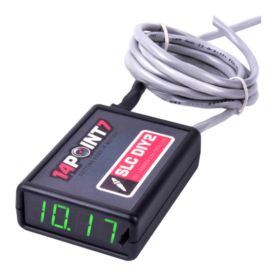
Summary of Contents for 14POINT7 SLC DIY 2
- Page 1 P a g e SLC DIY 2 Assembly Guide Required tools • Soldering iron • Solder • Philips screw driver • Wire cutters • Lighter/heatgun...
- Page 2 P a g e Cable Construction Lambda Cable Construction Required parts: • 1x black lambda connector • 6x lambda contacts • 6 conductor cable • 6 position molex connector • 6x molex contacts • 3x zip ties • Large heatshrink •...
- Page 3 P a g e Insert the cable end with the lambda contacts into the lambda connector, when you hear a “click” you will know the contacts are correctly inserted. Use the color code according to the above diagram. Push the purple locking mechanism to secure the contacts to the connector. Fit the large heatshrink over the lambda connector, the heatshrink is a bit small so you will have to widen the end slightly with your fingertips.
- Page 4 P a g e With a lighter, heatgun or similar, apply heat to the heatshrink tubing. Fit the small heatshrink tubing so that it overlaps the large heatshrink tubing by about 1 inch. With a lighter, heatgun or similar, apply heat to the heatshrink tubing. Secure the heatshrink to the connector and the cable using zip ties.
- Page 5 P a g e Power Cable Construction Required parts: • 4 conductor cable • 4 position molex connector • 4x molex contacts Trim 2 inches off the sheath of the 4 conductor cable, crimp/solder the lambda contacts to the cable, insert the contacts into the 4 position molex connector.
- Page 6 5 conductor cable The Auxiliary 2 Cable is soldered directly to the SLC DIY 2 PCB. Trim 2 inches off the sheath of the 5 conductor cable and solder the cable to the PCB. Use the color code according to the above picture.
- Page 7 P a g e Mounting PCB into the Case Mount the Display unit, Display panel, and SLC DIY 2 PCB into the case and secure using screws. Check to make sure the The distance from the hole in the display panel to the top metal screws are not touching any component on the PCB.


Need help?
Do you have a question about the SLC DIY 2 and is the answer not in the manual?
Questions and answers