Advertisement
Quick Links
Advertisement

Related Manuals for Allis-Chalmers LA-1600


Summary of Contents for Allis-Chalmers LA-1600
- Page 1 ALLIS-CHALMERS INSTRU'CTION BOOK AIR CIRCUIT BREAKER TYPE LA-1600 BWX-6638-5 APRil, 1967...
- Page 2 INDEX TO INSTRUCTION BOOK INSTALLATION AND INSPECTION SECTION INTRODUCTION WARRANTY RECEIVING AND INSPECTION FOR DAMAGE CAUTIONS�TO BE OBSERVED INSTALLATION STORAGE MAINTENANCE RENEWAL PARTS OPERATION SECT OESCRIPT ION Breaker Manually Opera t ed Breaker Electr i cally Ope rated RACKING MECHANISM. ORAWOUT INTERLOCK I NG BAR ll FT MAINTENANCE AND ADJU STMENTS...
- Page 3 AWS-CHALMERS OF ILLUSTRATIONS LIST LA- 1 600 TYPICAL OUTLINE TYPICAL OPERAT lNG tiECHAN ISH (MANUALLY OPERATED BREAKER) OPERATING MECHANISM (ELECTRICALLY OPERATED REAK WIRING DIAGRAM FOR ELECTRICALLY TYPICAL OPERATED BREAKERS & � TYPICAL RACKING MECHA NISM DRAWOUT INTERLOCK MAINTENANCE CLOSING TYP I CAL PANEL ASSEMBLY DEVICES TYPICAL STATIC OVERCURRENT T...
- Page 4 Jed at a m a once with the is d transportation compg n and Allis-Chalmers notified. CAUTIONS BE OBSERVED IN THE INSTALLATION AND CPE'RAT:O� 0 �� BREAKERS CIRCUIT makl ns t r�.:c:...
- Page 5 '''LA'' r circuit breaker Is '£ . l y adjusted, tested, and Inspected at the factory before shipment, but careful check should to be certain that shipment or storage has not resulted be m In damage or change adjustment. Circuit breakers should be Installed In a clean, dry, well-ventilated e in which the atmosphere is free Stat io n ary...
- Page 6 ALLI S - CHALM E RS �! " .,... 'i!•· I. < � ..·-" ··-- ,. ,...
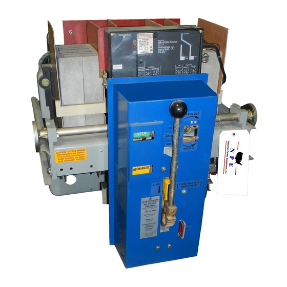
- Page 7 DESCRIPT I ON The LA-1600 air circuit breaker has an Interrupting capacity of 50.000 amperes and a continuous current rating of maximum lbO O amperes at 600 volts, bO cycles. For information on other voltages or frequencies. the factory should be consulted.
- Page 9 ALLIS -CHALMERS 202. SPRING RELEASE LATCH GEAR 202A. HOOD 236. PINS TRIP ROO TOGGLE UI<I<AGE PHON 238. MOTOR GEAR · BOX 210. CLOSING CAM LINK 239. MOTOR SPRING-POSITION SWITCH 240 GEAR SEGMENT 231. 241. MOTOR C'...U T ·OFF SWITCH SCREW 233.
- Page 10 The mechanism of the electrically-operated manut.ll breaker is the same as that of th e rate d breaker except that closing handle is manual ced by �n electric motor and the ge�r syste to Figures 2A Refer eme n of the control switch (N) located on the f r ont of to the "ON11 p osl tlon, when the control c...
- Page 11 AWS-CHALM E RS TRIP SHAfT VIEW FIG.4 TYPICAL RACKING MECHANISM DRAWOUT INTERLOCK 72·440·910.401 3,1967 N>ftiL,...
- Page 12 ,,_) Cublcle-mou' breakers drawout type parts the mechanism of the ac k the b the cubicle compartment, drawout trip Interlock drawout and the position markings. the breaker Lifting bar (401) lift Refer to F when cubicle. Is being Inserted In g sequence should With ion on...
- Page 13 ALLIS-CHALfVI E RS 205429 TYPICAL MAINTENANCE CLOSING HANDLE ElECTRICALLY O BREAKERS STEP 2 ...- 205430 MANUAL TRIP ROD . TYPICAL 2 DETAIL 11011) MAINTENANCE CLOSING HANDLE (REFER FIG. PROCEDURE (REFER TABLE FIGURE MAINTENANCE CLOSING...
- Page 14 SECTION II I, MAINTENANCE AND AOJUSTME� MAINTENANCE Occasional checking and c eanin g of the breaker will r vi n and A p e and trouble-free s servicing intervals six �onths or one year should be Included in the maintenance routine. Circuit breakers located In areas subject to acid fumes, cement...
- Page 15 ALLIS-CHALMERS 601. 607. STRAP 613. MAIN CONTACT 6 19. ARCING CONTACT 625. SPI.C£R 8-lSE 614. NUT 620. CONTACT 626. SCREW li02.CLEVIS 60ft. PAN 603. 621. SUPPORT 627. SPRING SPRING 609. STUD 61,. PIN 622. SPRING 604.SPACER 610. SCR(IY 628. CONNECTOR 62l.
- Page 16 During Inspection prior to installation and MAINTENANCE CLOSING: for routine maintenance Inspections, the breaker contacts may be closed slowly to check clearances, contact adjustments. and movement of links and latches. The manual closing handle is used for maintenance closing the breaker. Electrically•operated breakers do not have a manual closing handle, but a manual closing handle-cam assembly is available as a maintenance item.
- Page 17 205422 MODEL A- 1 . A-2 205421 110DE L AG, DU;'\L STATIC DUAL STAT I C TRIP DEVICE D E V I CE �l�I.\·(NA .. ��.r!') · - · . •. '!" .. 205420 MODE L D, 2054 19 HODE L DG SE L ECT I VE STAT I C S E LECT I V E STAT I C DEVICE...
- Page 19 (AMPS) ONE OR MORE U.S. PATENTS 3.177,407 TYPICAL BREAKER HATING PLAT E The current transformers each have five continuous current ratings. LA-1600 For the circuit breaker there are five groups of transformers shown in Table =-� ��- R ���S- _TAB _____ ______ -·...
- Page 21 • ALLIS-CHALM E RS r- ,' . � "1"' . . � � ol'lll · tt ·· · !, · ' � I /.�·::-. I� "'"·"':"."''·' "''"··· ::=-:.:.;:-..J 205424 205423 SHAFT LOCKS ·-· . ·---· .•. ---�-- CAUTION: LOOSEN SHAFT LOCKS ["...
- Page 23 AWS-CHALMERS 205 2 51 TEST POR T A B L E STAT I C TRIP OVERCUR RENT DEV I CES 205243 TEST TYP I CAL A R RA N G EMENT 2-24-67 F I G .
- Page 26 ALLIS-CHALMERS ., ... •• •• 1 . · ' . � •• • • ·, • • • � � � ; · ..!· . . � .. . · ..
- Page 27 to Figure 2) Latch Engagement Refer Trip latch (216) s engagement of .062" plus or minus have an with the latc .01511 on trip shaft (215). Measurement is made reset position. resting on the shaft in u re Main Contact Hake to Fig Refer between...
- Page 28 In t h cor rect p osition. Gear tp Figure 2A On LA-1600 breakers, prov i s i ons are made f o r s t ing the precise position where the gear toggle linkage disengages fr�n t he gear segmen t.
- Page 29 AWS-CHALM E RS 801. TRIP ARM TRIP ROD 80�. BREAKER 802. MAGNET 806. RESET CAM 803. PLATE 807. RESE T ARM 808. SPACE R 804. COIL 809. FIG. 8 TYPICAL RELEASE MAGNET 7 2-2 40-068-401 MAR.2,1967...
- Page 31 g e a r ( 2 3 5 ) a r e a t t h e top pos i t i on , t hey h a v e m o v e d pl unge r s h u t ( 2 3 3 ) a ga i ns t t h e r o l l e r o f mo to r c u t - o f f...
- Page 33 a n d pa r t of connec t or (624) T h e s t a t i on a ry a rc i ng c on t a c t i s t hi s c a s e , s crews (62 3 ) be re p l a ced by proceed i n g as a bove .
- Page 34 I · S E CT I ON I V , S TAT I C OV E R C U R R ENT TR I P D E V I CE • I· I NTRODUCT I O N T h e A l l i s - C h a l me r s S t a t i c Ove r c u r r e n t T r i p Dev i ce s e re ��n p l e t e l y s t a t i c ;...
- Page 35 f f 5 [ P ! PT I D N 0 � S T ! T ! C T R I P D E V I C E S s t a t i c t r i p s i m : l u r J i i f e r 171•) �...
- Page 36 CAUT i ON : N KNOBS ARE EQU I P P E D W i lli S HA FT LOC KS A L L E NS URE P E RMANEN C E S ETT I N G S . T U R N I NG A KNO B O N A W I L L CAU S E LOS S OF CA L l BRAT...
- Page 37 ALLI S - CHALM ERS SHIELD 1 1 04 . 11 0:1. M A R K I N G S T R I P 1 106. MARKING S T R I P 1 1 0 7. BRAC K E T 1 108.
- Page 39 .�U.!J..Q,tl_ : A LL S E LE CT I ON KNOBS ARE EQU I PP E D W I TH S LOC KS T U R N I NG A KNO B O N A E NS UR C: P E RMAN E N C E O F S ETT I NG S . LOC KE D �/ I L L C AU S E LOS S CA L l BRAT I ON .
- Page 41 ---· - --· • . . } · . •. :� . -� , FIG. 1 2 ' TYP ICAL AUXI L IARY MAR. 3, 196 7 7 1-2 4CH5'P HO I i .' � ! I ' 1 , · , ''·· th•...
- Page 43 S e l e c t i on G r ound P i ck -Up Mod e l s Mode l s The m i dd l e knob on the r i gh t hand s i de of t AG , O G .
- Page 44 B rea ke r ra t i n g a s p e r F i g u r e 7A . Phase p i c k - u p s e t t i n g 1 1 E 1 1 ( 1 0 00 ( 1 0 , 00 0 Am p s...
- Page 45 AWS - CHALM ERS .� ... "10. L ATC H I NG ARt.•S 1514. BELL ALARM RE LAY Llrt600 0NLY) 1515. SPAC E R NUTS (USED ON 151 1 . RESET RE LAY 1512. RELAY CONTACTS 1516. BRACKET 1 5 1 3. T E RIII INAL LUGS 1517.
- Page 47 J� 4:. \ ALLI S - C .. IALM ERS - - · -- · · O E TAIL "A" (SHOW N FRON RIGHT·HAHO SIOl OF I!I'I E A K ( R l 1409. LOC I\ N U T 1401. A I R POT T R I P B A fl 1410.
- Page 51 p i c k- u p B reake r ra t i ng pe r F i gu re 7A . Phas e s e t t i n gs "A " Lon g t J me Amps ) . b a n d s e t t i n g (500 I s on MAX I MUM .
- Page 52 MA I NT E NAN C E AND T E S T I NG M� i n t e n a n c e E a c h ove r cu r r en t t r i p dev i ce t ed c a l i b r a t e d , a n d t e �...
- Page 53 b l e vo l t a ge A 1 1 5 VAC t r a n s f o r me r w i t h e t l eas t 3 Amps ou t pu t . amm� t e r wh i ch w l 1 1 I nd i ca t e I 3 Amps w i t h rea s ona b l e...
- Page 54 P r oceed as f o l l ows : Fun c t i on Tes t - Connec t tes t c i r c u i t a s s hown Loosen l ocks s ha f t 1 1 A1 1 p I c k- u p knob s S e t...
- Page 55 R E LEAS E MAG NET The re l e a s e magnet I s i l l us t r a t ed I n e 8 . D u r i ng no rma l opera t i on , t r i p rod (80 1 ) wh i ch i s a t t ached t o a s p r i ng l oa d e d move a rma t u r e i ns i de the ma g ne t i c re l eas e l a t c h cy l i nde r cannot...
- Page 59 �- - --- · AU.IS-CHALME�S L I ST OF I L LUSTRAT I O� S F I GURE NO . D ESCR I PT I ON TYP I CA L 600 BR I NE TYP I CAL OPERAT I NG MECHAN I SM (MANUA LLY OPERATED BREAKE R) TYP I CAL OPERAT I NG ( E LECTR I CA LLY OPERATED BREAKE R) TY P...
- Page 60 I NSTRUCT I ONS fOR THE I NSTA LLAT I ON A�O OPERAT I ON ALL I S- CHAU'\ERS TYPE 1 1 LA 1 1 LOW VOLTAGE A I R C I RCU I T BREAK�RS AND AUX I L I ARY EqU I PM m_ T I ON I , t y pe "LA"...
- Page 61 £ . l e t I NSTALLAT I ON c i rc u i t b reake r I s c adj us ted , " LA" the fac t o ry before s h i pment , b u t ca ref u l check and I n s pec ted a t age has not res u l t ed thou l d be...
- Page 62 \. . , � t.u • - ¥11 11 1 � Ul'• - - Of:TAI\.·1 � � )> - � F. I TYPICAL LA-&10 BREAKER OUTUI'£ IIIA II CH ?l-44�6-401 7 , IM 1...
- Page 65 AWS - CHALM ERS 2 34. 202 SPRING RELEASE LATCH FLAT SPRING HOOD 202A GEAR 236. 207 TRIP ROO' PINS 2 1 0 TOGGLE L I NKAGE CLOSING CAM MOTOR GEAR-BOX PINON 225. LINK 239 MOTOR Gfo' 23Q SPRIIIG-POSITION SWITCH 2 4 0 GEA R SE 241.
- Page 66 ..T h e me c h a n i sm of t h e elect rlca lly -oper�t ed · e a k except t b re a k e r ' arne as t ha t of t he ma n u a l l y -opc r�...
- Page 68 RACK I NG i c l n t e ude as b reake r s of the d rawou t t y pe I nc I ra I s t he ch a r i p rack the b reake r I n and out of the cub i c l e...
- Page 69 � . S E CT J vN I I I . MA I NTE NANCE AND A D J USTMENTS a l chec k i ng a n d c l ean i n g o f t h e b r ea ke r w l I I MA I NT E NAN C E e r v p r omo t e l on g...
- Page 70 ALLIS-CHALM ER� il � l"=�·� �G HAN DL E N AN C E CLO S I � · 205429 T Y P I C AL MA I NT ENAN C E H A N D L E C L O S I N G EL E CT R I CAL L Y O P E R A T E D B R EA K ER S STEP S T E P 2...
- Page 71 ..' . tot A i hiE NANCE C LOS l NG : D u r i n g l n$ pe c t i on pr i o r t o I n s t a l l a t i on a n d f o r rc u t i ne ma i n tenance I ns p ec t i ons .
- Page 72 AWS -CHALM ERS SE T SCRE W WRENCH 6 19. CONTACT F �2�. SPACERS 601. P I N GE R 607. 8ASE 620. ARCING CONTACT 626. BAR 614. CONTACT 602 . SPACEI 608. SCREW 6 2 1 . N U T 627.
- Page 73 . • f e r t o F i p l us Tr i p l ( 2 1 6) . 0621 1 s hou l d h a ve e n g a g t o f m i n u s .
- Page 74 Re f e r t o F i g u r e 6 . C ONTACT RE P LAC E MENT Th e con t a c t s t r uc t u r e cons i s t s o f ma i n cu r r e n t c a r r y i n g con t a c t s a n d a r c i n g con t a c t s a r r a n g ed s o t h a t i n i t i a l con t a c t m a ke a n d f i n a l con t a c t b r ea k...
- Page 75 E i t h e r a r c i n g con t a c t b20) mov i ng o r ma i n con t a c t o r b o t h , m a y be r emoved a n d r e p l a ced a s f o l l ows : F o l l ow t he s t eps o u t l i ne d i n pa r a g r a ph i n c l ud i n g r em ov a l...
- Page 76 OV E R C U R R E NT T R I P S TAT I C D E V I C E St a t i c Dev i c e s T h e A l l i s -C h a l me r s O v e r c u r r e n t T r i p a r e I NTR O D U C T I O N...
- Page 77 D E S C R I PT I O N OF S TAT I C T R I P D E V I C E S T h e s e i ns t r uc t i ons d e s c r i be f o u r "'jS"';r s t a t i c...
- Page 78 CAUT I O N : A L L S E LE C T I ON KN OBS ARE EQU I PP E D W I TH S HAFT LOCKS TO E N S U R E PE RMANENC E OF S E TT I NG S . TURN I NG A KNO B O N A LO CKE D S HAFT W I L L CAUS E LOS S CA L I B RAT I ON .
- Page 79 Mode l s AG , DG . n o b de of t AG , The m i dd l e on t h e r i gh t h a n d Mod� l s u s ed t o s e l ec t the s en O G , of g r ound c u r r e n t d e t e c t i on .
- Page 80 EXAMP L E : B reake r e p i c k-up n g a s p e r F i g u r e s e t t i n g ( 400 Am (4000 E 1 1 I n s t a n ta n e o u s s e t t i n g l OX Amps ) .
- Page 81 EXAHPU: : B re a k e r r a t i ng a s p e r F i g u r e P h a s e p i c k - u p s e t t i n g s 7A .
- Page 82 Ma i n t enance E a c h s t a t i c o v e r c u r r en t t r i p dev i ce i s adj u s t e d , ca l i b ra t e d , a n d t es t ed b e f o r e s h i pmen t a n d I s ready f o r u s e a f t e r s e l e c t i n g a p p r op r i a t e s e t t i n g s a n d l oc k i n g t h e p o t e n t i ome t e r s ha f t s .
- Page 83 I 1 5 V A C v a r i a b l e vo l t a ge t r a ns f o rm e r w i t h a t l ea s t 3 Amps ou t pu t . 3 Amps r wh i c h w l I I An amm e...
- Page 84 F u n c t i on e d a T e s t - P r f o l l Con n e c t t e s t c i rc u i t a s s h own i n F i g u r e s h a f t Loos e n J oc ks...
- Page 86 T h e relea s e m a g n e t I s i ll u s t ra t ed I n F i g u re D u r i n g no rmal operat i on , t r i p r od (80 1 )
- Page 87 A LLI S - CHALM E RS ALLIS - CHAlMERS • aOftTON. M A S S M A CJ E. l ti U 5 A SER IAL. N U M B E R PIC K - U P SETI I N GS (AM PS) ONE OR MORE iJ PATENTS...
- Page 88 ALLI S - CHALM ERS .. . - - -- --1 · - - · - : , ' � : · _ ·nr . .. - ,, •• ,. I · I ' ! .. - \ l!t.i,( .. ,&IIJ III i ' ' •...
- Page 89 . . . ALUS - CHALM E RS 205 2 5 1 T EST P O R T A B L E S ET F O R S T AT I C O V E R C U R R E NT T R I P D EV I C E S .
- Page 90 ALLI S - Ci-IALM ERS F I G . 7 0...
- Page 91 ALLI S - CHALM ERS F I G . � ... o# · " "' _ ... _ ..- - . - ..- • -- • - - - �- . • • .•• .
- Page 92 ALLISaCHALM ERS TO CURRENT ON CIRCUIT TRANSFORMERS BREAKER _ _ _ - - - . - - - - -1 • • VA RIABLE VOLTAGE TRAHSFORIAER TO TA1P COIL ..,_ - - CIRCUIT BREAKER MODEL A· I,A-2 AG.AG-f.OG NODf:l TERMI N A L O, D-f MODEL �FER P»\RAGRAPH...
- Page 93 •' . AWS - CHALM ERS C A M ( O R E A K E R C L O S E D) P O S I T O N ( BR E A K E R OPE N ) �...
- Page 94 ALLIS- CHALM ERS 1 106. MARKING STRIP 1 1 0 7. BRAC K E T 1108. BRACKE T 1109. TERMINAL S C R E W 1 1 10. T ERMINAL TAB F l G. I I TY P ICAL S E C O N D A R Y D I SCONN E C TS r>EC.
- Page 95 ALLI S - CHALM E RS ·. r = h T R I P SH AF T l , v f-l- - - - -� � _ _ _ � - - l , � i • 1 3 0 1 . BR ACK E T 1 302.
- Page 96 • AWS -CI-tALMERS ,-- ··- --- - ,• r ·-- D E TAIL "A" (SHOWN RIGHT·HANO 510[ FROio! OF BR E A K E R ) 1409. LOC KNUT 1401. A I R POT 1410. T R I P BAR UP 8 1402.
- Page 99 •...
- Page 100 • • AWS-CHALM ERS : -----· . :. · · - f]) - - r-- - - -- ' J l . .p. r+ - I I I ' I I � I ' ' _ _ _ FIG. I 2 T Y P I C A L AUXI L I AR Y SW lTCH M AR.
Need help?
Do you have a question about the LA-1600 and is the answer not in the manual?
Questions and answers