
Related Manuals for Allis-Chalmers MA-75


Summary of Contents for Allis-Chalmers MA-75
- Page 1 • � . • 'f"" " AWS-CHALMERS INSTRUCTION BOOK TYPE "D'' MOVABLE PORT I ON MA·75/l50/250B RUPTAIR MAGNETIC POWER CIRCUIT BREAKER AND AUXILIARY EqUIPMENT (STORED�ENERGY OPERATOR) September I, 1966 Book No. BWXw6657w2...
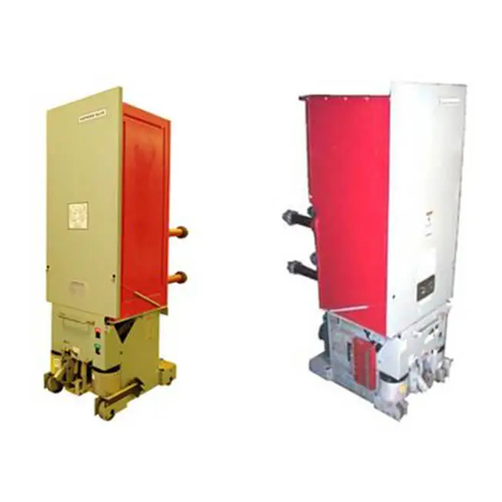
- Page 2 ALLIS-CHALMERS 4.16 kv , 1200 Amp., Front side view of Type 205395 Air Magnetic Circuit B reaker...
- Page 3 ALLIS-CHALMERS 205389 View shows application of fifth wheel on Type D Air Magnetic C ircuit B reakers...
- Page 4 ALLIS-CHALMERS Side view of Type D, kv, 1200 Amp., Air 4.16 217530 Magnetic Circuit B reaker, Outer Phase Barrier Removed.
-
Page 6: Table Of Contents
AWS-CHALMERS TABLE OF CO NTENTS ( SE-4, STORED ENERGY O PERATOR ) SECTION NO. CONTENTS PART DESCRIPTION I. I GENERAL METHOD OF ARC INTERRUPTION PART 2 ADJUSTMENTS GENERAL SE-4 STORED ENERGY OPERATOR PART 3 3. I DESCRIPTION OF OPERATOR 3. 1 (a ) DRIVING SYSTEM SPRING Ll N�GE ( c ) - Page 7 ALLIS-CHALMERS LIST OF ILLUSTRATIONS TYPE "D" MOVABLE PORT! ON MA-75/ 150/2508 RUPTAIR MAGNETIC POWER CIRCUIT BREAKER AND AUXILIARY EQUIPMENT (STORED ENERGY OPERATOR) FIGURE TYPICAL MAGNETIC BREAKER 7 1-40 1-645-40 1 FIGURE 2 TYPICAL ARC CHUTE 7 1-40 1-520-40 1 &...
-
Page 8: Part Idescription
PART I. DESC RIPTION GENERAL The AI is-C halmers RUPTAIR movable portion consists of a magnetic circuit breaker for metal-clad switchgear application, with auxiliary equipment suitably arranged for best function and easy installation. As part of standard equipment, each order is furnished with one maintenance closing device for solenoid operated breakers or a charging crank for stored energy operated units. -
Page 9: Part 2 Adjustments
PART ADJUSTMENTS � � GENERAL 2. 1 "\-- \ � The breaker has been completely set up, adjusted and tested at the factory. '\. "\ � Adjustments should not have to be made nor fastenin g s ti g htened when �... -
Page 11: Stored Energy Operator
PART 3 - SE-4, STORED ENERGY OPERATOR DESCRIPTION OF OPERATOR (Fig. 4) The stored energy operator consists of three systems: {a) the driving system, (b) the spring 1 inkage, and (c) the 4-bar closing 1 inkage, The systems are disengaged from each other except while performing their specific function;... -
Page 12: Closing Breaker
closing springs (4-6) will charge as soon as the breaker control Sho�ld the sp�ings not charge, check the motor �us is ene 3.13)" adjust;nent. Section ct·toff 1.see The springs ca� manually charged by inserting the charging handle guide tube (l-27) to engage the gearmotor. Rotate the handle do�n direction... - Page 13 into (1-27) g handle guide and engage ert spring tube direct ion in d irection with gearmotor. Turn handle indicated on shield resistance is felt. Pull manual until closing lanyard (1-26) and co�ti�ue The breaker handle. contacts wil slowly close. CA!JT!ON�...
-
Page 14: Main Toggle Roll
MAIN TOGGLE ROLL (Fig breaker is in the closed position with toggle roll (4-15) When against stop {4-59) the center of the toggle roll (4-15) should be 3/16 to 5/16 beyond the ine of centers of the latch rol 1 (4-14) and Adjustment is made by adding or removing shims (4-60). -
Page 15: Interlock Plunger
finger contacts are wired such that when movable portion is moved into test or operating position in the cubicle the finger contacts engage the contacts to complete the control circuit for stationary the breaker. ration of AUX!LIARY SWiTCtl (Fig. I I ) 3.11 sw!tch (l-15) has been adjusted at the factory and auxiliary... -
Page 16: Reset Relay
I reclose the 88-3aa switch and the motor will continue to run 3.14 RESET RELAY (For instantaneous Reclosure Service Only) The ALLiS-CHALMERS Reset Relay designed for use in circuit breaker control is a rugged electronic solid state time delay which operates a small relay"... - Page 17 AELAY CIRCUIT TYPI CAL RESET A constant voltage V c is maintained across the terminals AB by the two zener diodes Resistor R d drops the supply voltage to 0 2 . a value above the diode control voltage and the diodes further reduce the voltage to the control voltage value, V c .
- Page 19 The SCR is a latch type switch. Normally it blocks the flow of current through the relay R. When the gate terminal rece:ves a current pulse from the capacitor discharging through the UJT, the SCR allows current to flow through the relay R. The SCR conducts even after the pulse is removed.
- Page 20 For Parts Identification See Figure Shows breaker open - springs discharged. Motor starting springs charge with the driving cranks (4) picking up the rolls ( 2 4} inks (9) into tension and pul (19} back throwing ing latch rol of closing latch (13} . Driving cranks (4), turning counterclockwise, have gone overcenter throwing links (9) into compression with latch roll (19} against closing latch (13}.
- Page 21 Driving cranks (4) have forced rolls ( 2 4) to the point that Ill. inks (9 ) and (10) are slightly overtoggle, springs are fully inks (9 ) and (10) overtoggle against charged and will snap the stop. Driving cranks (4 ) have rotated free, inks (9) and (10) are overtoggle, springs fully extended ready for close when closing latch (13) is released.
- Page 22 C losing latch {13) has been re leased freeing latch ro l l (19) and a l lowing springs to drive links (9) and (10) forward as a unit. Latch rol l (1 9) forces togg le ro ll (15) forward �lith latch roll (14) he ld by trip latch (27) the breaker wi 11 c lose.
- Page 23 VI I . With the toggle broken between 1 inks (9) and (10) they snap back shown. V I I I Springs are recharged ready for next close operation. V I I I. Breaker p latch (27) has released latch roll has just been tripped.
-
Page 24: Part 4 Disconnect Sectjnn
PART 4. DI SCONNECT SECTION BREAKER MECHANISM The breaker mechanism consists essentia l ly of movab le contact arms and insu lating 1 inks which connect the contact arms to the operator mechanism. CONTACTS (Fig. 3) The st<1tionary contact structure of each phase is made up of two sets of contacts;... -
Page 25: Contact Pressure On Hinge Joint
1/32 inches.) If not already detached, remove pin (1-46) and detach link (l-47) from disconnect arms (3-18) and C-19). On MA-75/1508 and FC-150/250/500 Breakers - Detach arcing contact (3-10) from yoke (3-2) by removing pin (3-26). Move the disconnect toward the closed position until it just touches a main contact finger (See Fig. -
Page 27: Contact Lead
Be sure A I ignment is checked and adjusted on each phase separately. there are no binds between contacts (3-1 I ) preventing proper wiping action with the disconnect arms. Attach arcing contact (3-10) to yoke (3-2), if detached, but check contact lead (section 4.7), before attaching I ink (1-47) to disconnect arms (3-18) and (3-19). - Page 29 {1-33) Adjustment for dimension� is made by first removing pin on each {1-42), puffer. After loosening nut increase (or decrease) effective (1-40) length of rod end by screwing (or unscrewing) it into piston (J-44). {1-40) stem Adjust rod ends on both puffers the same amount. (1-42), {1-33), Tighten nuts...
-
Page 31: Part 5 Arc Chute Assembly
• PART ARC CHUTE ASSEMBLY & 5. I ARC CHUTE ASSEMBLY (Fig. 2 Each arc chute consists of a flame retardent envelope which provides phase isolation for interruption and venting of the by-product gases of interruption. The arc chute contains: T he transfer stack consisting of refractory plates. -
Page 33: Tilting Arc Chutes
• T o remove phase barriers on 15 kv breakers - remove screws (1- 13) and channels {1-9) on rear of breaker. Lower panel (1-32) and loosen three screws (1-23}; remove three screws {1- 24} and panel (1-22) on front of breaker. - Page 34 •...
- Page 35 • REAR BAR RIER (MA- 5 0 B ONLY) ARC CHUTE (SEE FIG. � POLE PIECE D> (SEE FIG. � INNER PHASE � BARRIER " REAR B A RR I E R OUTER BARRIER (MA-250 B ONLY � J> � �...
- Page 37 • BARRI E R POLE D> PI E CE -----, MOVING END )> ARC RUNNER STATIONA RY END A R C RUN NER COIL (FRONT) COI L )> � � FIG.2 TYPICAL ARC CHUTE JUNE 11,1962 71-401-520·401...
- Page 39 • (MA-250 B ONLY) ARCING CONTACT CONTACT FINGER (S TATIONARY' ( M A-75 150 B ONLY) (MOVING) D> VIEW "A-A" YOKE J> (ARCING CONTACTS ENGAGING) !::: "' l'------------- J> VIEW"A-/X.' � (BREAKER LATCHED) "' � S I LVER "' VIEW"B-B" FIG.3 BREAKER OPEN VIEW''A-A"...
- Page 40 • ·.
- Page 41 • 3 1 }- INTERLOCK SOLENOID CLOSING SPUR GEAR-( 3 COIL DRIVING CRANK LINK � P IN SHIM STOP GEAR )> MOTOR LINK HEX NU T "' TRIP SOLENOID TRIP COIL )> SPACER TRIP PIN TRIP LATCH "' � SCREW "' SPRING FIG.
- Page 42 •...
- Page 43 � MOTOR CUT-OFF D> CLOSE CIRCUIT J> J> ADJ. SCREW ADJ. SCREW LOCKNUT(A) LOCKNUT � '" LOCKNUT (C) FIG. 8 TYP ICAL CONTROL SW ITCH JULY 27,1966 72-4 20-020-4 0...
- Page 47 � • TO BREAKER TO BREAKER BREAKER OPENING BREAKER OP ENING PROP SPRING SPRING LATCH COIL (14} HOLDIN G MAGNET TRIP ARMATURE ARMATURE (14-) J TRIP ARI-orAT\JRE {1(,) TRIP COIL. HOOK LA"f(:H (16) (13) TRIP ARMATURE STOP I I (13) �...
Need help?
Do you have a question about the MA-75 and is the answer not in the manual?
Questions and answers