Table of Contents
Advertisement
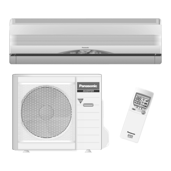
CS-E18CKR CU-E18CKR / CS-E21CKR CU-E21CKR
2003 Matsushita Industrial Corp. Sdn. Bhd. (11969-T). All rights
reserved. Unauthorized copying and distribution is a violation of
law.
1. Features
- Product
- Microcomputer-controlled compressor operating frequency
- Vertical and Horizontal Airflow Directions
- Five modes of operation selection
- Powerful Mode operation
- Delay ON Timer and OFF Timer
- Remote Control with illuminable buttons
Order No. MAC0306010C3
Room Air Conditioner
Advertisement
Table of Contents


Need help?
Do you have a question about the CU-E18CKR and is the answer not in the manual?
Questions and answers
Can I turn this on without a remote, can I also buy a new remote
Yes, the Panasonic CU-E18CKR can be turned on without a remote by using the "AUTO" switch on the indoor unit.
This answer is automatically generated