Advertisement
SE RVICE MANUAL
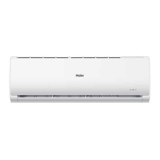
Wall Mounted Type
DC Inverter
Model No.
AS12TA2HRA-TH2
WARNING
Thi s servic e informatio n is designed for experience d repai r tec hnician s only and is not designe d for use by the genera l public.
It doe s not contai n warning s or caution s to advise non-technic al individu als of potentia l dangers in attemptin g to servic e a product.
Product s powere d by electricit y shoul d be service d or repaire d only by experience d professiona l technicia ns. Any attemp t to service or
Repai r the produc t or product s deal t with in this servic e infor mation by anyone else could res ult in seriou s injury or death
201 5 (Qing dao Haie r Air Condi tione r Genera l corp . , Ltd)
All right s reser ved. Unauthoriz ed cop ying and distributio n is a violati on of law
Haier Group
Version V1
Date 2017-02-03
Advertisement
Table of Contents

Subscribe to Our Youtube Channel
Related Manuals for Haier AS12TA2HRA-TH2


Summary of Contents for Haier AS12TA2HRA-TH2
- Page 1 Wall Mounted Type DC Inverter Model No. AS12TA2HRA-TH2 WARNING Thi s servic e informatio n is designed for experience d repai r tec hnician s only and is not designe d for use by the genera l public. It doe s not contai n warning s or caution s to advise non-technic al individu als of potentia l dangers in attemptin g to servic e a product.
-
Page 2: Table Of Contents
Table of contents Contents 1. Introduction .................... 1 2. Features ....................7 3. Specifications ..................8 4. Sensors list.................... 9 5. Piping diagrams ..................10 6. Printed circuit board connector wiring diagram........11 7. Functions and control ................8. Dimensional drawings ................9. -
Page 3: Introduction
Introduction 1. Introduction 1.1 Model name explanation Apply toT1; 220~240V50HZ/1ph DC inverter Indoor units Version number 25T Platform Platform of indoor units: T (T platform) Nominal cooling capacity (12000BTU/h) Type of indoor unit: S (wall-mounted) Indoor unit Domestic air conditioner... - Page 4 Introduction 1.2 Safety Cautions Be sure to read the following safety cautions before conducting repair work. The caution items are classified into “Warning” and “Caution”. The “Warning” items are especially important since they can lead to death or serious injury if they are not followed closely. The “Caution” items can also lead to serious accidents under some conditions if they are not followed.
- Page 5 Introduction Warning Do not repair the electrical components with wet hands . Working on the equipment with wet hands can cause an electrical shock Do not clean the air conditioner by splashing water. Washing the unit with water can cause an electrical shock.
- Page 6 Introduction Warning Be sure to use an exclusive power circuit for the equipment, and follow the technical standards related to the electrical equipment, the internal wiring regulations and the instruction manual for installation when conducting electrical work. Insufficient power circuit capacity and improper electrical work can cause an electrical shock or fire. Be sure to use the specified cable to connect between the indoor and outdoor units.
- Page 7 Introduction Caution Installation of a leakage breaker is necessary in some cases depending on the conditions of the installation site, to prevent electrical shocks. Do not install the equipment in a place where there is a possibility of combustible gas leaks. If a combustible gas leaks and remains around the unit, it can cause a fire.
- Page 8 Introduction Caution Check to see if the parts and wires are mounted and connected properly, and if the connections at the soldered or crimped terminals are secure. Improper installation and connections can cause excessive heat generation, fire or an electrical shock. If the installation platform or frame has corroded, replace it.
-
Page 9: Features
Features 2.Features Super quiet: Lower noise operation condition A-PAM DC inverter:With adoption of S-TYPE,S-PAM and PHASE control technology to works more stably at low-frequency,and is more energy-saving,mor powerful at high frequency. Long distance air supplying: Heating: When -15 can still heating natural heating maintenance:Heating Holding 10 temperature Confortable sleep The setting temperature and the indoor noise can be adjusted to a more comfortable... -
Page 10: Specifications
Specifications 3 Specifications NOMINAL DISTRIBUTION SYSTEM VOLTAGE NOMINAL CAPACITY and NOMINAL INPUT n i l 3.7 1.1-5.2 3.6 1.0-4.1 Capacity rated Btu/h 12630 3750-17750 12280 3420-14000 o i t 1.12 1.02 o i t 1039 ³ 1.6*10 ³ TECHNICAL SPECIFICATIONS 820 195*280 Packaged Dimensions 909*279*355... -
Page 11: Sensors List
... -
Page 12: Piping Diagrams
Piping diagrams 5 Piping diagrams Domestic air conditioner... -
Page 13: Printed Circuit Board Connector Wiring Diagram
Connector for fresh air Note: Other designations PCB(1) (Indoor Control PCB) 1) CN48 Connector for Forced operation ON / OFF switch 2) FUSE1 Fuse 3.15A/250VAC N_RC UNIT MODEL PCB MODEL 0011800381B AS12TA2HRA-TH2 387* 317* S2/DISPLAY SERIES 324* 325*/498* 387* 317* UNTI MODEL... - Page 14 Printed circuit board connector wiring diagram PCB(1) Domestic air conditioner...
- Page 15 Printed circuit board connector wiring diagram Wiring diagrams Transformer C0N3 C0N1 C0N2 Fresh air CN21 Fan motor CN21 CN18 up-down stepmotor CN11 CN23 CN31 left stepmotor CN12 Right stepmotor CN35 WIFI CN17 Central controller CN48 CN36 EMERGENCY SWITCH AMBIENT TEMP SENSOR PIPING TEMP SENSOR DISPLAY POWER SUPPLY...
-
Page 16: Functions And Control
Functions and control 7.Funcitions and control 7.1 Main functions and control specification 7.1.1 Automatic operation When the running mode is turned to automation after starting the system, the system will first determine the running mode according to the current room temperature and then will run according to the determined mode. - Page 17 Functions and control 7.1.3 Dehumidifying mode. * temperature control range: 16---30 * temperature difference: 1 Control feature: send the dehumidifying signal to the outdoor system. When Tr>Ts+2 , the compressor will be turned on, the indoor fan will operate at the set speed. When Tr is between the Ts and Ts+2 , the outdoor system will operate at the high dehumidifying frequency for 10 minutes and then at the low dehumidifying mode for six minutes.
- Page 18 Functions and control If Tr<Ts-1 , the outdoor system will be turned on again, the indoor fan will be at the cold air proof mode. *Indoor fan control manual control: You can choose high, medium, low and automatic speed control. Automatic: When Tr<Ts, high speed.
- Page 19 Functions and control Entering ‘mute’, you can have normal operation or signal control such as timing to finish the strength operation. When the system is at the automatic option with the strength/ mute function, if the system enters the cooling mode, the cooling strength/ mute function will be offered; if the system enters the heating mode, then the heating strength/ mute function will be offered;...
- Page 20 Functions and control 2 centigrade after 1 hour’s operation and will fall 2 centigrade 1 hour later. 3 hours after the preceding operations, the set temperature will be raised for 1 centigrade and the system will keep this status for 3 hours and then close down.
- Page 21 Functions and control 7.1.12 High load protection control The outdoor system will be stopped if the coil temperature is above 65 for 2 minutes. The indoor fan will be controlled by the thermostat. The outdoor system can be restarted when the coil temperature is below 42 and the system has been stopped for 3 minutes.
- Page 22 Functions and control can be confirmed and reported and the outdoor system will be stopped. 7.1.16 Single indoor system operation * Enter condition: First, set the high speed airflow and 30 centigrade set temperature, then press the dormant keys for 6 times within 7 seconds, the system will feedback with 6 rings. * After the system enters the separate indoor system operation mode, the indoor system will operate according to the set mode and neglect the communication signals of the outdoor system.
- Page 23 Functions and control Temp.( ) Resistor K Temp. Resistor K Temp. Resistor K 266.905 32.215 250.866 30.671 5.87 235.895 29.21 5.65 221.911 27.828 5.44 208.838 26.521 5.24 196.609 25.283 5.04 185.163 24.111 4.86 174.443 4.68 164.399 21.94 4.51 154.983 20.94 4.35 146.153 19.99...
- Page 24 Functions and control B25 /50 =3700K±2% Temp.(( )) Max.(K ) Normal(K ) Min.(K ) Tolerance( ) 165.2170 147.9497 132.3678 -1.94 1.75 155.5754 139.5600 125.0806 -1.93 1.74 146.5609 131.7022 118.2434 -1.91 1.73 138.1285 124.3392 111.8256 -1.89 1.71 130.2371 117.4366 105.7989 -1.87 1.70 122.8484 110.9627...
- Page 25 Functions and control 20.9688 19.9409 18.9463 -1.13 1.09 20.0176 19.0621 18.1358 -1.11 1.07 19.1149 18.2270 17.3646 -1.08 1.05 18.2580 17.4331 16.6305 -1.06 1.03 17.4442 16.6782 15.9315 -1.03 1.01 16.6711 15.9601 15.2657 -1.01 0.99 15.9366 15.2770 14.6315 -0.98 0.96 15.2385 14.6268 14.0271 -0.96 0.94...
- Page 26 Functions and control 3.7878 3.5654 3.3531 -1.78 1.70 3.6601 3.4416 3.2332 -1.82 1.74 3.5374 3.3227 3.1183 -1.87 1.78 3.4195 3.2085 3.0079 -1.91 1.82 3.3060 3.0989 2.9021 -1.95 1.85 3.1969 2.9935 2.8005 -2.00 1.89 3.0919 2.8922 2.7029 -2.04 1.93 2.9909 2.7948 2.6092 -2.08 1.97...
- Page 27 Functions and control 1.0030 0.9061 0.8179 -3.85 3.51 0.9756 0.8806 0.7941 -3.90 3.55 0.9490 0.8558 0.7711 -3.96 3.60 0.9232 0.8319 0.7489 -4.01 3.64 0.8983 0.8088 0.7275 -4.07 3.69 0.8741 0.7863 0.7067 -4.12 3.74 0.8507 0.7646 0.6867 -4.18 3.78 0.8281 0.7436 0.6672 -4.23 3.83...
-
Page 28: Dimensional Drawings
Seivice diagnosis 8.Dimensional drawings unit:mm 9.Center of gravity unit:mm Domestic air conditioner... -
Page 29: Service Diagnosis
Service diagnosis 10. Service Diagnosis 10.1 Caution for Diagnosis The operation lamp flashes when any of the following errors is detected. 1. When a protection device of the indoor or outdoor unit is activated or when the thermistor malfunctions, disabling equipment operation. 2. - Page 30 ...
- Page 31 ...
- Page 32 ...
- Page 33 ...
- Page 34 ...
- Page 35 Service diagnosis Check whether Terminal on the outdoor mainboard is well inserted. Reinsert the terminals Is it normal? Electrify the machine again and turn it on in the Cool state with the remote controller. check whether motor can Measure the voltage between 1 and 3 of the terminal of fan motor on the mainboard about DC310V, Measure the voltage between 3 and 4 of the terminal about DC15V.
- Page 36 Service diagnosis 10.3.5 IPM protection Outdoor display: LED1 flash 2 times Method of IPM protection is detected by checking the compressor running condition and so on Malfunction Detection Malfunction The system leads to IPM protection due to over current Decision The compressor faulty leads to IPM protection Conditions circuit component of IPM is broken and led to IPM protection...
- Page 37 Service diagnosis 10.3.6 Over-current of the compressor Outdoor Display: LED1 flash 3 or 24 or 25 times Method of The current of the compressor is too high Malfunction Detection Malfunction when the IPM Module is damaged Decision or the compressor is damaged. Conditions power supply voltage is too low or too high Supposed...
- Page 38 Service diagnosis Electrify the machine again and turn it on with the remote controller, If malfunctions IPM Module is damaged and are reported before or upon the compressor needs replacing. being started up, The compressor is started normally, but malfunctions are reported after it has Repair the power supply run for some time.
- Page 39 Service diagnosis 10.3.7 The communication fault between IPM and outdoor PCB Outdoor display: LED1 flash 4 times Method of Communication is detected by checking the IPM module and the outdoor PCB Malfunction Detection Malfunction The outdoor PCB broken leads to communication fault Decision The IPM module broken leads to communication fault Conditions...
- Page 40 Service diagnosis 10.3.8 Power Supply Over or under voltage fault Outdoor display: LED1 flash 6 times The power supply is over voltage Method of An abnormal voltage rise or fall is detected by checking the specified voltage detection circuit. Malfunction Detection Malfunction An voltage signal is fed from the voltage detection circuit to the microcomputer...
- Page 41 Service diagnosis 10.3.9 Overheat Protection For Discharge Temperature Outdoor display: LED1 flash 8 times Method of The Discharge temperature control is checked with the temperature being detected Malfunction by the Discharge pipe thermistor Detection Malfunction when the compressor discharge temperature is above 110 Decision Conditions Supposed...
- Page 42 ...
- Page 43 Service diagnosis Check the indoor mainboard. Measure the voltage between Jumpers 3 and 4 of IC1 on the indoor mainboard with a multimeter. Test the outdoor power supply (230VAC and +310VDC) with a multimeter. If the voltage is of a constant value of 0V DCto5V DC If 230VAC is available but 310DC not, the power module is damaged, replace it...
- Page 44 Service diagnosis 10.3.11 Loss of synchronism detection Inverter side current detection is abnormal Outdoor Display LED1 flash 18 times LED1 flash 19 times Method of The position of the compressor rotor can not detected normally Malfunction Detection Malfunction when the wiring of compressor is wrong or the connection is poor; Decision or the compressor is damaged Conditions...
- Page 45 ...
-
Page 46: Circuit Diagrams
Circuit diagrams 11. Circuit Diagrams TJC8-04 0.1uF 1-3-MODE 0603 1-6-RST 1-12-SCL 1-11-SDA 0603 560 -0805 TJC8-04 IC4 CAT24C04-SOIC8 5267-04A CN35 0.01uF 1-48-COM2 KI1/AN9/P11 0.1uF S8B-PH-K-S( 1-41-TXD 1-47-ROOM 100 -0805 KI2/AN10/P12 R103 1-40-RXD 100 -0805 P33/SSI 1-46-PIPE KI3/AN11/P13 P34/SDA/SCS 1-45-IR 100uF-16V-105 1-3-MODE (INT2)/P32 1-42-COM1... - Page 47 Circuit diagrams 891WP-1A-C(AC220V-20A- 0603 ±5 N500 0603 ±20% 2SD1781KT146R CN18 RLS4148 R500 +12V CN18' 2-33-POWER_ON 4.7K R501 D250 JZC-32F(AC220V-5A- ULN2003A-SOIC16 IC10 CN11' CON1 2-32-DD RLS4148 2-31-DC CON3 2-30-DB 220V-L 2-29-DA +12V 220V-N CON2 RLS4148 +12V N501 KRC119S 0.1uF 4.7K 835L-1AB-C(AC220V-8A- 2-34-HEAT +12V 2-58-JZ-R...
- Page 48 Sincere Forever Haier Group Edited by : Jing Yanqin Haier Industrial Park, No.1, Haier Road Yang Xiaodong 266101, Qingdao, China_ Signed by : He shiquan Http //www.haier.com Approved by: Wu Hongjin Domestic air conditioner...
- Page 49 Repair the product or products dealt with in this service information by anyone else could result in serious injury or death 2015 (Qingdao Haier Air Conditioner General corp. , Ltd) All rights reserved. Unauthorized copying and distribution is a violation of law...
- Page 50 Removal Procedure Removal of front panel front panel Remove the foam cushion Loosen the screw Domestic Air Conditioner...
- Page 51 Removal Procedure Lift up the control box cover Loosen the screw Lift up the control box cover Domestic Air Conditioner...
- Page 52 Removal Procedure Removal of front panel Pull the wires out of the control box and then release the pivots on both sides of the unit to remove the front panel. Remove the air filters Domestic Air Conditioner...
- Page 53 Removal Procedure Remove the casing three Domestic Air Conditioner...
- Page 54 Removal Procedure horizontal flap and the stepper motor flap Loosen the screws and remove the stepper motor Domestic Air Conditioner...
- Page 55 Removal Procedure horizontal louver and control box Every blade go round and round,then move Loosen the screws Domestic Air Conditioner...
- Page 56 Removal Procedure Loosen the hook and the service Cover Lift up the exchanger and remove it Domestic Air Conditioner...
- Page 57 Removal Procedure motor cover Domestic Air Conditioner...
- Page 58 Removal Procedure Domestic Air Conditioner...
Need help?
Do you have a question about the AS12TA2HRA-TH2 and is the answer not in the manual?
Questions and answers