Table of Contents
Advertisement
Quick Links
SERVICE MANUAL
•PARTS LIST(The difference between MDS-EX77 and MDS-EX770)
Page
Ref. No.
Part No.
–––––––
–––––––
1
X-4947-652-1 PANEL ASSY, FRONT
3
4-985-889-01 BUTTON(REC)(CD SYNC, REC)
4
4-985-890-01 BUTTON(MODE)
5
4-985-891-01 BUTTON(EJECT) ( EJECT)
6
4-985-894-01 BUTTON(EDIT)
68
7
X-4947-763-1 BUTTON(F/R)ASSY(
8
4-985-892-01 BUTTON(PLAY)(
* 15
4-985-899-11 CASE
* 16
4-985-898-12 PANEL(MDS), BACK
23
4-985-896-01 KNOB(REC)
24
4-985-925-01 KNOB(JOG)
• Items marked "*" are not stocked since they
are seldom required for routine service.
Some delay should be anticipated when
ordering these items.
MICROFILM
9-922-856-11
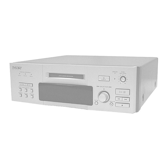
MDS-EX770 is the mini disk deck section in DHC-EX770MD.
The mechanical and electorical specifications of MDS-EX770 is almost
same as MDS-EX77.
So this manual contains only the points which differ from MDS-EX77.
For the informations not contained in this manual, please refer to the
MDS-EX77 service manuals (9-960-938- ) previously issued.
MDS-EX77
Description
–––––––––
,
)
, )
Sony Corporation
Home A&V Products Company
MDS-EX770
Ref. No.
Part No.
–––––––
–––––––
1
X-4949-866-1 PANEL ASSY, FRONT
3
4-985-889-11 BUTTON(REC)(CD SYNC, REC)
4
4-985-890-11 BUTTON(MODE)
5
4-985-891-11 BUTTON(EJECT) ( EJECT)
6
4-985-894-11 BUTTON(EDIT)
7
X-4949-931-1 BUTTON(F/R)ASSY(
8
4-985-892-31 BUTTON(PLAY)(
* 15
4-985-899-71 CASE
* 16
4-985-898-21 PANEL(MDS), BACK
23
4-985-896-21 KNOB(REC)
24
4-985-925-11 KNOB(JOG)
AEP Model
UK Model
MDS-EX770
Description
–––––––––
,
)
, )
MINI DISC SYSTEM
98D001648-1D
Printed in Japan ©1998.4
Published by Quality Assurance Dept.
(Shibaura)
Advertisement
Table of Contents


Need help?
Do you have a question about the MDS-EX770 and is the answer not in the manual?
Questions and answers