Advertisement
Quick Links
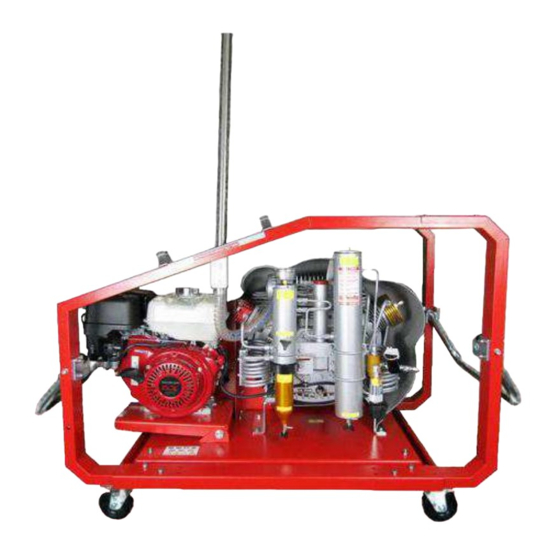
DO NOT USE WITH ENRICHED AIR SYSTEMS, ABOVE 21% OXYGEN
(the use of enriched air, above 21% oxygen, will void manufacturer's warranty)
High Pressure Breathing Air Compressors
Model # Max-Air 90 PBAC
Owner's Operating Manual & Parts List
MAX-AIR • 2807 Peddler Lane • Kerrville, Texas 78028 • USA • 830-257-5006 • FAX 830-257-3720
www.max-air.com
Max-Air is a registered trademark with the U.S. patent office – copyright 2006.
This manual cannot be reproduced without the express written permission of Max-Air.
WARNING!
service@max-air.com
9.0 cfm
Revised 6-30-21
Advertisement

Related Manuals for Max-Air Systems 90 PBAC


Summary of Contents for Max-Air Systems 90 PBAC
- Page 1 DO NOT USE WITH ENRICHED AIR SYSTEMS, ABOVE 21% OXYGEN (the use of enriched air, above 21% oxygen, will void manufacturer’s warranty) High Pressure Breathing Air Compressors Model # Max-Air 90 PBAC 9.0 cfm Owner's Operating Manual & Parts List MAX-AIR •...
- Page 2 Thank you for choosing MAX-AIR, where quality and commitment give you the best in technology and support available today. Be sure to ask your MAX-AIR dealer about our complete line of compressors and accessories. This owner's manual uses signal words recommended by the American National Standards Institute (see ANSI Z535.4) to designate levels of hazards.
- Page 3 TECHNICAL DESCRIPTION Model: MAX-AIR 90(9.0cfm) Weight: 276 lbs (125kg) w/9 HP Honda engine Dimensions: 42"L x 20"W x 28.5"H Construction: Air cooled, three stage, three cylinder high pressure compressor, all stainless steel interstage cooling Max. pressure: 340 bar (5000 psig) Approx.
- Page 4 2.2 Working System Ambient air, which must be free from exhaust fumes, is drawn through the intake filter and inlet valve into the 1st stage cylinder, where it is pre-compressed. A portion of the compression heat is dissipated through the valve head, piston, cylinder, crankcase and lubricating oil to the cooling airflow.
- Page 5 DANGER 2.3.3 Safety valves The safety valves prevent damage to the compressor by overpressure and are factory set at the following pressures: 1st stage: 113 psi (8 bar) 2nd stage: 725 psi (50 bar) 3rd stage: 5000 psi (340 bar). In case a safety valve blows, do not adjust to a higher pressure but check for the cause.
- Page 6 Filling hoses must be in perfect condition, connecting threads faultless. Particular attention should be paid to damage of the connecting fittings. If the rubber is scored, the hose must not be used any longer because water can enter and attack the wire gauze. In that case it is not guaranteed that the hose is able to hold the pressure.
- Page 7 4.2 Starting-up Before starting engine check oil level in the crankcase of the horizontally placed compressor (§ 4.8.1) Use MAXLUBE 501 synthetic oil. Starting of the engine: Before starting electric motors, check voltage. Electric connections must comply with the respective regulations.
- Page 8 4.4 Shutdown procedure On compressors using gasoline drive, close hand lever on carburetor and turn "On/Off" switch off. Close fuel cylinder valve and drain condensate out of compressor. In addition, check oil level of compressor, gasoline level in engine tank and carry out current service (§ 4.8). 4.5 Preparation for extended storage Prior to extended storage, the compressor should run a few minutes against a small backpressure of approximately 300PSI (20 bar), by partly closing filling valve in order to prevent possibility of corrosion.
- Page 9 WARNING 4.8.2 Safety valve control The final safety valve protects the 3rd stage and the high-pressure cylinders and is factory set to 10% above the requested filling pressure. The safety valve of the 3rd stage must be checked for proper functioning periodically.
- Page 10 condensate often, derate by 10% for every 5 F above 72 F. The reverse applies for temperatures below 72 Important for filter maintenance: Service only when unit is turned off and totally depressurized. Check filter case, threads and O-rings and maintain or replace if necessary. It is recommended to record the quantity of pressure cylinders filled in order to reassure that the precise replacement intervals are kept.
- Page 11 Maintenance after operating hours: Hours Recommended Service Check valve heads. Intake piping must be hand warm; outlet piping must be hot (§2.2) First oil change (§4.8.1) check tension of v-belt (§4.8.3) Maintenance of intake filter (§4.8.4) Check tension of v-belts (§4.8.3) Check fixation of cooler and belt guard (§4.8.9) Oil change (§4.8.1) Check tension of v-belt (§4.8.3)
- Page 12 4.9.4 Tightening torque screw thread max. torque hex. screw 1,0 kpm / 7 ft-lbs inner hex. Screw hex screw 2,5 kpm / 18 ft-lbs inner hex. Screw hex. screw M 10 4,5 kpm / 32 ft-lbs inner hex. screw Valve head screw requires torque wrench tightening Page 11 of 22...
-
Page 13: Troubleshooting
Trouble Shooting Trouble Cause Remedy Gas engine does not start See operating manual Electric motor does not start One phase failed Check fuses Safety valve 1 blows off 2nd stage valves Clean valves or defective replace Safety valve II blows off 3rd stage valves Replace defective... - Page 14 2807 Peddler Lane Kerrville Texas 78028 Ph. 830-257-5006 Fax. 830-257-3720 Email service @max-air.com www.max-air.com Compressor Pumping Group Identification Sheet Model Max-Air 55, 90 and 180 Twin INSIDE Figure 1. Oil Level Sight Glass Intake filter housing Oil and water separator (high pressure) Valve Head 1st Stage 15.A.
- Page 15 YOU MUST READ AND UNDERSTAND THIS INFORMATION PRIOR TO FILLING BREATHING AIR CYLINDER!! BREATHING AIR PURIFICATION FILTER CARTRIDGE (DISPOSABLE) Part Number LF-65247 Fits all Max-Air compressors with upgraded purification PU-35000 for breathing air Typical processing capacity (cartridge life) @ 72 F intake temperature for Grade “E”...
- Page 16 C. D. E. Close up view of plastic plug “E” at bottom of cartridge. A. Seal Foil envelope not shown Part Number LF-65247 35,000 cft @ 72 F @ 5000psi Page 15 of 22...
- Page 17 YOU MUST READ AND UNDERSTAND THIS INFORMATION PRIOR TO FILLING BREATHING AIR CYLINDER!! BREATHING AIR PURIFICATION FILTER CARTRIDGE (DISPOSABLE) Part Number LF-1002 Fits only compressor model Max-Air 90 with standard filtration Typical processing capacity (cartridge life) @ 72 F intake temperature for Grade “E”...
- Page 18 14 1/4” x 1 3/4” dia. Part Number LF-1002 10,000 cft @ 72 F @ 5000psi NOTE: Dimensions exclude threaded plastic nipple w/O’ring Page 17 of 22...
- Page 19 CARBON MONOXIDE ELEMENT #MI-4002R DESCRIPTION This detector consists of a ‘Visual” indicator (#MI-4000), into which a small (15 mm diameter) replaceable disc is inserted. The ‘Visual’ indicator has a clear sight lens through which the disc may be seen. The disc changes color in the presence of low concentrations of carbon monoxide within 5 to 10 minutes of exposure and therefore acts as a clear visible warning before the proportion of gas reaches an unacceptable level.
-
Page 20: Maintenance
Assembly and Disassembly BLEED ALL PRESSURE FROM UNIT AND SHUT OFF POWER Model MI-4000 Visual Indicator Unscrew by hand , counter-clockwise, to remove and replace elements. Reinstall cap hand tight. Item Part No. Description Body Window 592-1 O ring 2-018 592-2 O ring 2-019 592-3... - Page 21 Remove top half of element housing and invert. Place the blue moisture indicator down inside element against the glass taking care not to touch the blue element with your fingers. Place the beige element on top of the spring. Re-attach the top half of the element housing hand tight. DANGEROUS DO NOT USE AIR...
-
Page 22: Warranty
Warranty IMPORTANT: The materials supplied by Max-Air are covered by a 12-month warranty, the validity of which begins on the date of delivery as proven by the delivery document. Max-Air shall repair or replace those parts it acknowledges to be faulty during the warranty period. In replacing the faulty part Max-Air shall not be liable for any other expenses sustained by the dealer or his customer such as presumed damage (present or future), lost earnings or fines. - Page 23 NOTES _________________________________________________________________________________ _________________________________________________________________________________ _________________________________________________________________________________ _________________________________________________________________________________ _________________________________________________________________________________ _________________________________________________________________________________ _________________________________________________________________________________ _________________________________________________________________________________ _________________________________________________________________________________ _________________________________________________________________________________ _________________________________________________________________________________ _________________________________________________________________________________ _________________________________________________________________________________ _________________________________________________________________________________ _________________________________________________________________________________ _________________________________________________________________________________ _________________________________________________________________________________ _________________________________________________________________________________ _________________________________________________________________________________ _________________________________________________________________________________ _________________________________________________________________________________ _________________________________________________________________________________ _________________________________________________________________________________ _________________________________________________________________________________ _________________________________________________________________________________ _________________________________________________________________________________ _________________________________________________________________________________ _________________________________________________________________________________ _________________________________________________________________________________ _________________________________________________________________________________ _________________________________________________________________________________ _________________________________________________________________________________ _________________________________________________________________________________ _________________________________________________________________________________ _________________________________________________________________________________ _________________________________________________________________________________ _________________________________________________________________________________ _________________________________________________________________________________ Page 22 of 22...
Need help?
Do you have a question about the 90 PBAC and is the answer not in the manual?
Questions and answers