Advertisement
Quick Links
Advertisement

Related Manuals for DAS AUDIO LARA

Summary of Contents for DAS AUDIO LARA
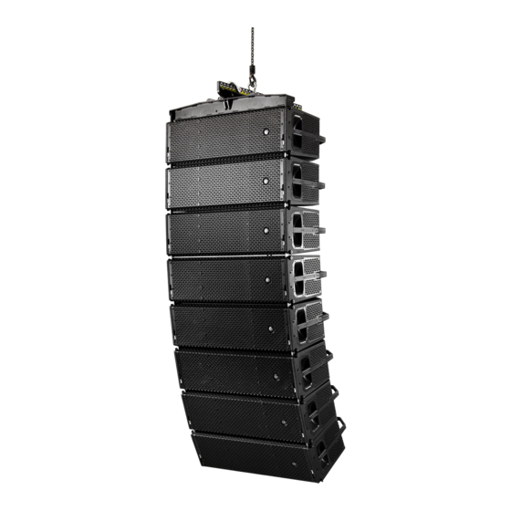
- Page 1 LARA AND LARA-SUB RIGGING MANUAL LARA manual / LARA - SUB...
- Page 2 Assembly and use of AX-PULL-LARA Assembly of JP-LARA on a LARA-SUB unit for stacking LARA units on top Flying a cluster of 2 or 3 LARA-SUB units after transport platform is removed FUN-4-LARA installation. With and without AX-LARA FUN-2-LARA-SUB and FUN-3-LARA-SUB installation...
-
Page 3: Safety Precautions
SAFETY PRECAUTIONS This manual offers all the necessary information for flying Rigging hardware should be regularly inspected and DAS Audio systems. This document contains safety precautions defective units replaced discarded. It is highly recommended that you implement an equipment inspection and maintenance and a description of the elements to be used. - Page 4 2.-Assembly of LARA unit on its transport platform. Disassembly Fig.1 Fig.1 Fig. 2 Remove the two front security pins from the LARA unit and release the connecting rods. Gently place the unit inserting the connecting rods into the dedicated slots of the transport platform. Fig.2 To attach the LARA unit to the transport platform, insert the security pins into the front holes of the platform as shown in the figure.
-
Page 5: Video-Tutorial
2.- Video-tutorial Stack four LARA on top of PL-LARA Click or scan the code LARA manual / LARA - SUB... - Page 6 3.- Assembly of a LARA-SUB unit on its transport platform. Disassembly Fig.1 Fig.1 Fig. 2 Only use the PL-LARA-SUB accessory (WLL 400kgf) shown in the figure to stack and transport up to 3 units of LARA-SUB. Fig.2 Place the LARA-SUB unit on the platform aligning its feet with the marks on the platform.
- Page 7 4.- Assembly of GS-PL-LARA. Play angle settings in LARA units. Stability, max. and min. angle and maximum number of units Fig.1 Fig. 1 Fig. 2 The figure shows the PL-LARA (WLL=400 kgf) accessory. Fig.2 The GS-PL-LARA accessory can be at- tached to the PL-LARA to provide addi- tional stability in ground stacked LARA (WLL=400kgf) applications. Fig.3 The figure shows how the different parts of the accessory fit into the correspond-...
- Page 8 4.- Assembly of GS-PL-LARA. Play angle settings in LARA units. Stability, max. and min. angle and maximum number of units Fig.5 As shown in the figure, the splay angles between two adjacent LARA units can range from 0 to 7 degrees maximum (the numbers on the rear plates of the LARA units indicate the splay angles in de- grees). When shipped from the factory, the units have a security pin stowed in the “PIN...
- Page 9 4.- Video-tutorial GS-LARA installation Click or scan the code LARA manual / LARA - SUB...
- Page 10 5.- Assembly of 4 LARA units with TOP-PL-LARA on platform Fig.1 Fig.1 Fig. 2 Stack the first LARA unit on the platform as previously described in this manual. To attach the following unit, remove the top security pins of the bottom unit. Align the two units and remove the two bottom security pins of the upper unit. Lower the connecting rods and make sure the holes are aligned correctly. Fig.2 Re-insert the four security pins to attach the two LARA units at the front.
- Page 11 5.- Assembly of 4 LARA units with TOP-PL-LARA on platform Fig.7 Fig.7 Fig. 8 Follow the same steps to stack further units, the result can be seen in the figure. Fig.8 Rear view. LARA manual / LARA - SUB...
- Page 12 5.- Assembly of 4 LARA units with TOP-PL-LARA on platform Fig.9 Fig.9 Fig. 10 Fig.11 To attach the TOP-PL-LARA to the unit on top, first, remove the two upper security pins from the LARA unit. Fig.10 Lower the TOP-PL-LARA, align the holes and attach with the two security pins. Fig.11 Align the TOP-PL-LARA rear bracket with the last hole oin the LARA rear plate.
- Page 13 5.- Video-tutorial Stacking four LARA units on PL-LARA TOP-PL-LARA Assembly Click or scan the code Click or scan the code LARA manual / LARA - SUB...
- Page 14 6.- Storage of platforms with TOP-PL-LARA during a show Fig.1 Fig.1 Fig. 2 Fig.3 Align the platform with the top as shown in the figure. Fig.2 View from below. Remove the three security pins from their housing. Fig.3 Attach the top with the security pins, as shown in the figure. Fig.4 The figure shows the two accessories together in a single block. Fig.5 These blocks can be piled up, fitting the Fig.4 Fig.5 Fig.6 wheels into the slots as shown in the figure.
- Page 15 7.- AX-LARA introduction: FRAME + PICK-UP unboxing Fig.1 Fig.1 Fig.2 The AX-LARA accessory is packed in a wooden crate, as shown in the figure, due to its weight. Fig.2 To open it, remove the two security pins through the square openings in the crate, as shown in the figure. Fig.3 Now you can remove the lid. Fig.3 Fig.4 Fig.4 The figure shows the two parts that make up the accessory: the FRAME and the PICK-UP. Fig.5 Attach the two parts with the pins as shown.
- Page 16 8.- Assembly of AX-LARA on a LARA unit. Max. number of units. LARA units AX-LARA (flying/transport mode). Ease Focus coverage figure Fig.1 Fig.1 Fig.2 The figure shows how to attach the AX-LARA accessory (WLL=2100kgf) to a LARA unit. To do this, remove the LARA´s upper front pins, align the holes with the accessory and attach with the same pins. Fig.2 The result can be seen in the figure. Fig.3 Now it is time to attach the back.
- Page 17 8.- Assembly of AX-LARA on a LARA unit. Max. number of units. LARA units AX-LARA (flying/transport mode). Ease Focus coverage figure Fig.6 Fig.6 Fig.7 Fig.8 Remove the PIN HOLDER pin from the LARA. Fig.7 Finally, insert the pin at “1” (=0+1) to lock the assembly. This is the correct way to transport the accessory on top of LARA units stacked on their platform.
- Page 18 8.- Assembly of AX-LARA on a LARA unit. Max. number of units. LARA units AX-LARA (flying/transport mode). Ease Focus coverage figure Fig.11 Fig.11 Fig.14 Fig.15 The figure shows the two rear connecting rods of the accessory. One on the FRAME and the other on the PICK-UP. Fig.12 For a standard configuration, the PICK- UP connecting rod is folded away with a security pin.
- Page 19 8.- Assembly of AX-LARA on a LARA unit. Max. number of units. LARA units AX-LARA (flying/transport mode). Ease Focus coverage figure Fig.16 Fig.16 Fig.17 To obtain the desired tilt, attach the accessory to the splay angle hole indicated by the Ease Focus software. The figure shows the numbers displayed on the label of the PICK-UP accessory.
- Page 20 AX-LARA From assembly and transportation transportation mode to flying mode with AX-LARA Click or scan the code: Click or scan the code: Flying four Adding LARA LARA units systems to the array LARA manual / LARA - SUB...
- Page 21 9.- AX-LARA on LARA units with inverted PICK-UP (Tilt-up). Ease Focus coverage figure Fig.1 Fig.1 Fig.2 Start with the PICK-UP folded on the FRAME, as shown in the image. Remove the pin that lock the PICK-UP in place. Fig.2 Attach the PICK-UP, as shown in the image, with the inverted PICK-UP (Tilt-up), extending to the front of the LARA unit.
- Page 22 9.- AX-LARA on LARA units with inverted PICK-UP (Tilt-up). Ease Focus coverage figure Fig.4 Fig.4 Fig.5 Fig.6 The figure shows an uptilted configuration. Fig.5 Side view of the same configuration. Fig.6 Ease Focus simulated coverage for this type of configuration. (EASE FOCUS: 10 LARA Uptilt) LARA manual / LARA - SUB...
- Page 23 To attach the AX-LARA on a LARA-SUB unit, first note the AX-LARA figure with the rear connecting rods unfolded. Fig.2 To attach the accessory to a LARA unit, the outer connecting rod had to be fold- ed away. However, to attach the accesso- ry to a LARA-SUB unit, fold away the con- necting rod shown in the figure and lock it with a security pin. Fig.3 The result can be seen in the figure. Attach the LARA-SUB following the same steps as with the LARA units, i.e., first, at- tach the two upper front pins and then a pin to the rear connecting rod.
- Page 24 10.- Video-tutorial Flying two LARA-SUB Click or scan the code LARA manual / LARA - SUB...
- Page 25 11.- V-AX-LARA assembly and use Fig.1 Fig.1 Fig.2 The V-AX-LARA allows you to tilt the array systems horizontally and prevents them from swinging, by adding a third pickup point to the array. Fig.2 The result can be seen in the figure. LARA manual / LARA - SUB...
- Page 26 After removing the accessory and the shackle, as shown in the figure, use the accessory to obtain a lower pickup point for the system. Fig.2 The figure shows the point where the AX-PULL-LARA is attached to the bottom unit. Fig.3 The result can be seen in the figure. Fig.4 The system will look as illustrated in the figure. The lower pickup point helps the Fig.2...
- Page 27 13.- JP-LARA assembly on a LARA-SUB unit for stacking a LARA unit Fig.1 Fig.1 Fig.2 On the top of the unit, you can find a pair of screws in the center, close to the back of the cabinet. These screws will be used to attach the JP-LARA (WLL 270kgf) ac- cessory.
- Page 28 13.- JP-LARA assembly on a LARA-SUB unit for stacking a LARA unit Fig.5 Fig.5 Fig.6 Once the LARA cabinet is placed on the sub, release the two front connecting rods and align them with the holes. Next, insert the two previously removed pins. Fig.6 Once the front is securely attached, it is time for the back. Fig.7 Remove the security pin that locks the rear connecting rod of the cabinet.
- Page 29 13.- JP-LARA assembly on a LARA-SUB unit for stacking a LARA unit Fig. 11 Fig.11 Fig.12 Fig.13 Before adding another unit, remove the two pins at the front of the cabinet as be- fore. Fig.12 Place the next unit on top, lower the two front connecting rods and align them with the pin holes.
- Page 30 13.- JP-LARA assembly on a LARA-SUB unit for stacking a LARA unit Fig.18 Fig.18 Fig.19 Back view. The result can be seen in the figure. Fig.19 Front view. The result can be seen in the figure. LARA manual / LARA - SUB...
- Page 31 13.- Video-tutorial LARA and LARA-SUB groundstack with JP-LARA Click or scan the code LARA manual / LARA - SUB...
- Page 32 14.- Flying a cluster of 2 or 3 LARA-SUB units after transport platform is removed Fig.1 Fig.2 Fig.1 To fly a LARA-SUB array, which is usually transported in clusters of 2 or 3 units on their platform, first attach the AX-LARA to the unit on top, removing the two upper front pins of the unit.
- Page 33 14.- Flying a cluster of 2 or 3 LARA-SUB units after transport platform is removed Fig.5 Fig.5 Fig.6 Lift the cluster as shown in the figure. Fig.6 To add another cluster below, proceed as before. The maximum allowed weight that the AX-LARA can handle (WLL) is 2100kgf. LARA manual / LARA - SUB...
- Page 34 14.- Video-tutorial Flying two LARA-SUB Click or scan the code LARA manual / LARA - SUB...
- Page 35 15.- FUN-4-LARA installation. With or without AX-LARA Fig.1, Fig.2 and Fig.3 Fig.1, Fig.2 and Fig.3 Without AX-LARA or Top Without AX-LARA or Top Open the rear velcro and put the cover on from the top. The velcro should be at the back and the cover´s “front” indicator should be at the front. Pull down the cover and adjust it. Finally, close the rear velcro. Fig.4 With AX-LARA Repeat the steps above, but this time, expand the cover at the top using the corresponding zipper. Fig. 4 Fig.
- Page 36 15.- Video-tutorial Cover over AX-LARA Cover features Click or scan the code Click or scan the code LARA manual / LARA - SUB...
- Page 37 16.- FUN-2-LARA-SUB and FUN-3-LARA-SUB installation Fig.1 Two stacked units will require the FUN-2- LARA-SUB accessory shown in the figure. Three units will require the FUN-3-LARA- SUB. Both have flaps that can be folded away so it is not necessary to remove the covers to access the cabinets. LARA manual / LARA - SUB...
- Page 38 17.- Using the FUN-2-LARA-SUB or FUN-3-LARA-SUB during a show (stacked usage) Fig.1 Fig.1 Fig.2 For two units, use the FUN-2-LARA-SUB accessory shown in the figure in transport mode, with the flaps down. Note that the FUN-3-LARA-SUB will be used for three units in the same way. Fig.2 The flaps are attached with Velcro and are easy to open. Fig.3 To use the equipment without removing the cover, simply fold the flaps over the top of the equipment as shown.
Need help?
Do you have a question about the LARA and is the answer not in the manual?
Questions and answers