Table of Contents
Advertisement
Quick Links
Advertisement
Table of Contents

Subscribe to Our Youtube Channel
Related Manuals for MCS MCS16

Summary of Contents for MCS MCS16
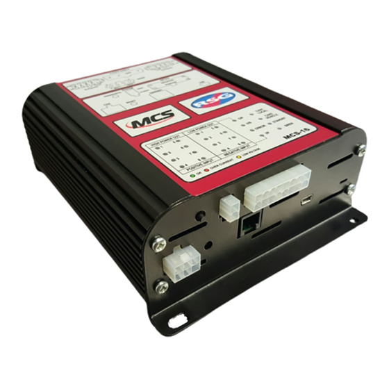
- Page 1 MCS16 INSTALLATION GUIDE...
-
Page 2: Table Of Contents
MCS16 Installation Guide 1V1 CONTENTS Pre-Installation ........................... 3 1.1) Required Tools ........................3 Installation ............................3 2.1) Mounting ..........................3 2.3) Power Inputs (CON2) ......................4 2.4) Power Outputs (CON1 & CON3) ..................4 2.5) Configurable Outputs (CON1 & CON3) ................4 2.6) -
Page 3: Pre-Installation
MCS16 Installation Guide 1V1 MCS16 Installation Guide 1V1 1) Pre-Installation 1.1) Required Tools • Crimping Tool 1 Mega Fit Connector Mega Fit Connector - Molex part number: 63825-7100 http://uk.farnell.com http://uk.farnell.com Part Number: 2383206 • http://www.digikey.co.uk/ http://www.digikey.co.uk/ Part Number: WM10384-ND •... -
Page 4: Power Inputs (Con2)
MCS16 Installation Guide 1V1 MCS16 Installation Guide 1V1 4 x M4 holes are supplied for mounting the unit to a base panel. mounting the unit to a base panel. 2.2) Wiring Power In and Outputs 2.3) Power Inputs (CON2) Name... -
Page 5: Siren Speaker Connector
Name Function Remote Power 12V Output for CAN Remotes. Protected with a 500mA resettable fuse. CAN 1 High Use CAN1 with MCS System Handsets and Expansion Modules CAN 1 Low Ground CAN 2 High Use CAN2 with Vehicle CAN Only. -
Page 6: 1) Rs485
MCS16 Installation Guide 1V1 2.11) RS485 Name Function Microphone Input Ground Common RS485 Data RS485 Data 12VDC 12V Supply Output 1000mA Max. PTT Sw PTT Active Low. 3) Diagnostics CAN1 Off: No local CAN devices in use Green: All local CAN devices ok... -
Page 7: Volume Setting
4) Volume Setting To set the volume levels for the MCS16, follow the following procedure: 4.1) Press and hold the MCS16 Diagnostic Button on the side of the unit (this is located next to the System Connector). 4.2) While holding the MCS16 Diagnostic Button, press and release the reset button (this is located just below the diagnostic button). -
Page 8: Version History
MCS16 Installation Guide 1V1 6) Version History Version Changes Responsible Date Person(s) AES Spec 5 Requirements Added and E-Marking included 30 Aug 2016 Page 8 of 8...
Need help?
Do you have a question about the MCS16 and is the answer not in the manual?
Questions and answers