
Related Manuals for MCS MCS-Magnum

Summary of Contents for MCS MCS-Magnum
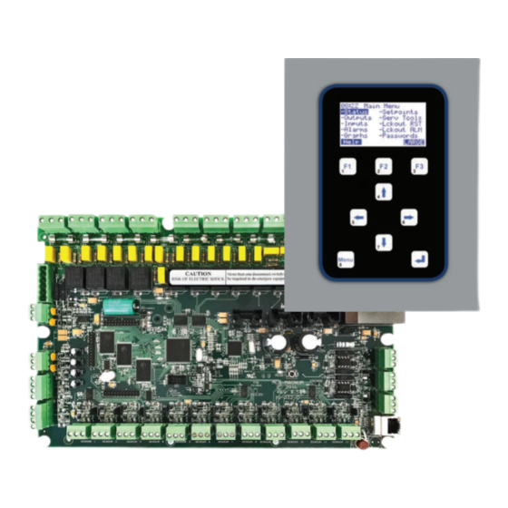
- Page 1 MCS-Magnum Controller System Simplified Description and Troubleshooting Plus MCS-MAGNUM Alarms and Safeties Revision 2.05B Revision 2017-11-07...
- Page 2 Phone: (239) 694-0089 Fax: (239) 694-0031 www.mcscontrols.com Information contained in this manual has been prepared by Micro Control Systems, Inc. and is company confidential and copyright © protected 2017. Copying or distributing this document is prohibited unless expressly approved by MCS.
-
Page 3: Table Of Contents
Appendix E 1.1. Analog Sensor Input Reference Table ..................................17 Appendix F 1.1. MCS-UPC Status LED Code Descriptions ..................................18 Magnum Alarms and Safeties 1.1. There are four types of alarms that are generated by the Magnum control logic: .......................19 1.2. Information Only Alarms ......................................19 1.2.1... -
Page 4: Mcs-Magnum Controller Troubleshooting
MCS-MAGNUM CONTROLLER TROUBLESHOOTING... -
Page 5: Troubleshooting General Dead Board Symptoms
1.1. Troubleshooting General Dead Board Symptoms Measure voltage at ac If board has a Voltage voltage selector Ac input input connector block and Start verify that it is within 10 fuse blown? switch, is it set percent of rated voltage correctly? Turn power off, set Replace fuse. -
Page 6: Troubleshooting Sensor Input Problems
1.2. Troubleshooting Sensor Input Problems If system uses expansion boards, verify MCS-I/O communication by Check that all sensor input seeing if red TX light blinks on all Analog / Digital jumpers Start boards and also check for proper are set correctly and all... -
Page 7: Troubleshooting Relay Output Problems
At the connector base connector block to outbound controlled is there less than 1 device. Also, if board is a MCS-I/O or ohm of resistance Replace board Magnum Micro Controller Systems RO8 refer to Appendix K for possible... - Page 8 1.4. Troubleshooting Lost I/O Communication Problems Verify that MCS I/O Verify that MCS I/O Verify that address wiring between boards jumpers on all termination jumper is Start expansion boards are on first and last board is correct, especially Magnum was locked...
-
Page 9: Entering Authorization Codes To Log In And Out Of A Magnum
Appendix A 1.5. Entering Authorization Codes to Log In and Out of a Magnum 09:56 Main Menu -Status -Setpoints -Outputs -Serv Tools -Inputs -Lckout RST First, at the Main Menu use the arrow keys to navigate to Passwords: -Alarms -Lckout ALM -Graphs -Passwords Help... -
Page 10: Appendix A (Continued)
Appendix A (continued) 1.6. Entering Authorization Codes to Log In and Out of a Magnum 09:56 Password Level – Factory The Magnum will tell you if it accepted your code and the level of authorization. Then Press ‘ ‘ Key For example, if you entered a valid factory authorization code you will see the following: 09:56... -
Page 11: Manually Turning On And Off A Magnum Relay Output
Appendix B 1.1. Manually Turning On and Off a Magnum Relay Output 09:56 Main Menu -Status -Setpoints -Outputs -Serv Tools Note: If a relay is in a Lockout state you cannot manually turn it on or off. -Inputs -Lckout RST -Alarms -Lckout ALM First, after logging into the Magnum with your authorization code... -
Page 12: Appendix B (Continued)
Appendix B (continued) 1.2. Manually Turning On and Off a Magnum Relay Output 09:56 Outputs Relays Status M-1 COMP1-1 Off. Use the up and down arrow keys to cycle through the three modes for the relay output: COMP1-1 M-2 LOAD1-1 Manual MANON AUTO, MANON or MANOFF... -
Page 13: Determining And Changing The Network Address Of A Magnum
Appendix C 1.1. Determining and Changing the Network Address of a Magnum 09:56 Main Menu -Status -Setpoints -Outputs -Serv Tools -Inputs -Lckout RST First, at the Main Menu use the arrow keys to navigate to Serv Tools: -Alarms -Lckout ALM -Graphs -Passwords Help... -
Page 14: Appendix C (Continued)
Appendix C (continued) 1.2. Determining and Changing the Network Address of a Magnum 09:56 RS-485 Setup Protocol Address Baud Rate 19200 Address Now press the Enter key. You should see something similar to the following: Back, 09:56 RS-485 Setup Protocol Address Baud R Use the up and down arrow keys to select the Address number:... -
Page 15: Sensor Input Reference Table
To troubleshoot analog sensor input problems and determine where the problem is, simply remove the sensor input connector block of the input you want to test and plug in a MCS-SENSOR-TEST block. If you do not have a MCS-SENSOR-TEST block you can connect a 100K ohm 1% ¼... -
Page 16: Appendix D (Continued)
500p STAT 50 23.5” STAT CO2 M 50-KW 43.6K -999p M 75-KW 65.1K STAT.25 -9.99” M100-KW 86.6K STAT0.2 0.07” MCS 667 100.0P STAT1 % 1233.6% MCS CO2 1001p STAT1 F 1233.6% MCS-200 100.0P STAT2 % 4.8% MCS-500 100.0P STAT2 F -99.9F... -
Page 17: Magnum Alarms And Safeties
TurboCor Compressor Alarms All alarms have the same format. The alarm is identified and is date/time stamped. Alarms can be viewed from the Magnum keypad by selecting the ‘Alarms’ from the main menu, or through MCS-Connect. 1.2. Information Only Alarms 1.2.1 System Generated Alarms... -
Page 18: User Initiated Alarms
1.3.1 Configuration Alarms These alarms indicate a problem with the configuration file in the system. The system is not operational and a new configuration must be transmit- ted to the unit through MCS-Connect. INVALID CONFIG – Checksums are incorrect. „... -
Page 19: Mcs Local Network Alarms
„ number of the board will be displayed with the alarm. The system can be accessed but will be in a NO RUN- I/O LOST state. MCS-STAT OFFLINE – The Magnum has lost communications to the MCS-STAT. „ LOST IO SHUTDOWN – Generated when Magnum is running and there are no communications to one or more of the I/O boards. The „... -
Page 20: Sensor Inputs Used With Magnum Setpoint Safeties
1.4.1 Sensor Inputs Used With Magnum Setpoint Safeties: Suction Pressure(Analog or Digital) „ Discharge Pressure (Analog or Digital) „ Oil Pressure (Analog or Digital) „ Oil Differential Pressure (Calculated value) „ Oil Temperature (Analog or Digital) „ Discharge Temperature (Analog or Digital) „... - Page 21 Low Differential Oil Pressure This safety is designed to meet the compressor manufacturer requirements on oil pressure. For the first 5 seconds following a compressor start (60 seconds if Hitachi screw compressor) this safety is NOT checked. For the next 30 seconds, if the oil differential pressure drops below ½ of the value of the Setpoint or the digital input turns ON for the time specified in the ‘Time (sec)’...
-
Page 22: Turbocor Compressor Alarms
High Motor Amperage If the amperage analog input rises above the value of the compressor’s respective FLA Setpoint #171 – 190 times the value of Setpoint #75 or the digital input turns ON for the time specified in the Time (sec)’ field, then the circuit will be Locked Out and a HIGH MOTOR AMP alarm generated. Refer to section 11 Setpoint #75. - Page 23 Cavity Temperature Fault (Hex code =0x0020) The measured Cavity Temperature has exceeded either the Alarm or Fault limit, probably due to insufficient motor cooling (shaft cavity). Leaving Fluid Temperature Fault (Hex code =0x0040) The measured Air / Water Temperature has exceeded either the Alarm or Fault limit, probably due to insufficient air / water flow. Pressure Ratio Fault (Hex code =0x0080) The measured Compression Ratio of Discharge and Suction has exceeded either the Alarm or Fault limit, probably due to faulty condenser or insufficient load on the evaporator.
- Page 24 Winding Temperature Fault (Hex code =0x1000) The measured motor winding temperature has exceeded 155ºC. Superheat Fault (Hex code =0x2000) The Fault limit is based on the suction pressure and temperature values. There is no time delay on this fault or alarm. The difference between the fault limit and alarm limit is the dead band for the control.
- Page 25 Providing HVAC/R Control Solutions Worldwide 5580 Enterprise Pkwy. Fort Myers, FL 33905 Office: (239) 694-0089 Fax: (239) 694-0031 www.mcscontrols.com...
Need help?
Do you have a question about the MCS-Magnum and is the answer not in the manual?
Questions and answers