
Related Manuals for Thwaites MACH 2071 2022


Summary of Contents for Thwaites MACH 2071 2022
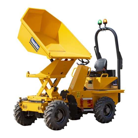
- Page 1 2.0 - 3.0 Tonne (hydrostatic) MACH 2071, 2076, 2077, 2080, 2081. Operator’s Instruction Manual Mach 2077 - 2.3 Tonne Powerswivel Mach 2071 - 2.0 Tonne Hi Swivel...
-
Page 2: Safety Symbols
Due to the varied nature of the operation of site dumpers and the absence of an agreed test standard, any figures quoted It is the policy of Thwaites Limited to promote safety in the by Thwaites in relation to vibration values and exposure are operation of its machines and to create a general awareness of for reference purposes only. -
Page 3: Before Operating This Machine
Before operating this machine Read this operator’s instruction manual Distributor Contact your Thwaites dealer in case of further questions Learn to operate this machine Ensure that you are fit to operate Wear correct safety clothing and ensure that safety equipment is available... -
Page 4: Safety Label Identification
Safety label identification 20% max 25% max 25% max 16% max 25% max 20% max 16% max 20% max 25% max 25% max 20% max 25% max 20% max 20% max Complete checks in section before starting the engine... -
Page 5: Safety Labels
Safety label identification Safety labels The safety labels fitted to these machines are to warn the operator or bystanders of possible hazards. • Be sure you fully understand the content and position of the labels. • Ensure labels are clean and in good condition, do not clean labels with solvents. •... - Page 6 Before operating this machine Visually check the machine Are the chassis lock and the skip lock disengaged? Are the controls, crush zone or hydraulic rams clean, and clear of any debris? Walk around the machine Is the Roll-Over Protective frame (ROPS frame) secure, fully upright and undamaged? Is the seatbelt anchorage secure and serviceable? Are the covers and mudguards secure?
- Page 7 Before operating this machine Mount the machine and check the controls Use the grabrails and foot steps provided to manoevre into seating position. Face the machine at all times when mounting and dismounting Is the engine cover secure and locked? Adjust the seat position for comfort and easy access to controls Fasten the seatbelt.
-
Page 8: Layout Of Controls
Layout of controls Control location & functions Steering wheel Direction indicator selector - forward = left turn - back = right turn* 2 & 3 Lights - twist 1 = sidelights ON twist 2 = headlights ON* Hazard warning light switch* Foot brake pedal Throttle pedal Hand brake lever... - Page 9 Layout of battery Maxi fuse Isolater switch Hour meter CB1 Transmission CB2 Power CB3 Lights* / Becon / Horn CB4 Hazard* / Lights* CB5 LH side lights* CB6 RH side lights* * Optional items Complete checks in section before starting the engine...
-
Page 10: Seat Adjustment
Control functions – explained Seat adjustment A – Turn knob to set driver weight B – Lift to slide seat assembly forwards/backwards C – Lift handle to adjust backrest Adjusting the seat belt • Adjust length of belt when seated on the machine •... - Page 11 Control functions – explained Tip-skip lever (forward tip model) • Push forward to tip skip • Push backwards to return skip Rotate-skip lever (swivel models) • Raise skip 100 mm (4”) to disengage pivot centring lock Rotate skip, fully lowered, to automatically engage centring lock •...
- Page 12 Control function – explained FNR lever • Push forwards to travel in a forward direction • Lever centred = neutral • Pull back to travel in a reverse direction • Twist lever anti-clockwise for HIGH-speed travel • Twist lever clockwise for LOW-speed travel If green beacon option is fitted seat belt must be buckled for lever to function Hand brake lever - right hand...
-
Page 13: Steering Wheel
Control functions – explained Steering wheel • Turn the wheel clockwise to turn machine to right • Turn the wheel anticlockwise to turn machine to left Ensure the non-steering hand is on the engine cover grabrail when using the spinner knob for low-speed single-handed steering Throttle pedal –... - Page 14 Control functions – explained Raising and Lowering the folding ROPS frame • Remove linch pins and withdraw frame lock pins • Lower frame and insert lock pins and linch pins in new position • Reverse the procedure to raise the frame •...
-
Page 15: To Start The Engine
How to START and STOP the engine To start the engine • Apply hand brake • Set FNR lever to neutral • Cold start aid (when required)- Turn key to position ‘H’. When panel light extinguishes start engine (as above). •... -
Page 16: Preliminary Checks
Preliminary checks Function checks - engine ON Brakes • Does the foot brake pedal feel firm? • If the hand brake is on, and a gear is selected, a buzzer will sound and the drive may be disconnected. Steering • Rotate steering wheel clockwise and anti-clockwise Electrics •... - Page 17 Driving procedure and parking safely Moving from rest and stopping If green beacon option is fitted seat belt must be buckled. • Select forward or reverse • Select low gear • Release hand brake fully • Slowly depress accelerator to move away •...
- Page 18 DANGER IMMEDIATE HAZARDS WHICH WILL RESULT IN SEVERE PERSONAL INJURY OR DEATH WORKING ON GRADIENTS Swivel Skip DO NOT exceed maximum stated gradients DO NOT turn across gradients DO NOT brake suddenly in wet, muddy, icy conditions or when operating on loose surfaces DO NOT run downhill with controls in neutral DO NOT operate skip-raise lever (Hi swivel model) on sloping ground.
- Page 19 DANGER IMMEDIATE HAZARDS WHICH WILL RESULT IN SEVERE PERSONAL INJURY OR DEATH CRUSH ZONE Stay clear of articulation area when the engine is running Never operate machine controls when standing on either side of machine WORKING UNDER A RAISED SKIP Lock skip safety prop during maintenance Never work under an unpropped skip When using skip safety prop engage tip-skip lever lock...
- Page 20 DANGER IMMEDIATE HAZARDS WHICH WILL RESULT IN SEVERE PERSONAL INJURY OR DEATH VISIBILITY Mach 2071 The visibility maps show machines in standard build and travel configuration. The maps provide an approximate indication of what can be seen by the operator and any blind spots when seated in the driving position wearing a seatbelt.
- Page 21 DANGER IMMEDIATE HAZARDS WHICH WILL RESULT IN SEVERE PERSONAL INJURY OR DEATH Mach 2077 Mach 2076 1.2m 1.2m 0.45m 0.45m 4.35m 4.7m Operators field of vision Operators field of vision Blind spots Blind spots Attention! Section correct and incorrect working practices...
- Page 22 DANGER IMMEDIATE HAZARDS WHICH WILL RESULT IN SEVERE PERSONAL INJURY OR DEATH Mach 2080 Mach 2081 1.2m 1.2m 0.6m 0.6m 6.2m Operators field of vision Operators field of vision Blind spots Blind spots Attention! Section correct and incorrect working practices...
-
Page 23: Unloading The Machine
WARNING HAZARDS OR UNSAFE PRACTICES WHICH COULD RESULT IN SEVERE PERSONAL INJURY OR DEATH LOADING THE MACHINE DO NOT exceed the machine’s rated capacity Activate the hand brake, set drive to neutral, turn the engine off, disembark the machine, and stand clear Clear any debris from controls Ensure SAFE STABLE LOW load which allows good visibility Reduce payload if materials being carried are not free flowing... - Page 24 WARNING HAZARDS OR UNSAFE PRACTICES WHICH COULD RESULT IN SEVERE PERSONAL INJURY OR DEATH DRIVING DO NOT drive with NEVER dismount from the skip tipped a moving machine (bulldozing) DO NOT carry Avoid confined passengers work areas - exhaust fumes and noise can be a hazard Site hazards to avoid: DO NOT operate...
-
Page 25: Towing A Trailer
DO NOT exceed maximum tow bar pull or vertical load. Towing must not be carried out on sloping ground. Always use Thwaites-approved towing pin. TRANSPORTATION When transporting or storing machine with the ROPS frame folded down remove beacons and secure beneath the bonnet. - Page 26 CAUTION HAZARDS OR UNSAFE PRACTICES WHICH COULD RESULT IN MINOR PERSONAL INJURY OR PRODUCT OR PROPERTY DAMAGE LIFTING Tip skip fully forward Engage skip safety prop Engage chassis locking bar Lift using centre eye provided HAND BRAKE DO NOT apply hand brake if machine is moving (except in an emergency) SCISSOR LIFT Insert locking pin when working beneath skip...
- Page 27 CAUTION HAZARDS OR UNSAFE PRACTICES WHICH COULD RESULT IN MINOR PERSONAL INJURY OR PRODUCT OR PROPERTY DAMAGE HINGED ROPS Use grab handles, tread grips (if fitted) and steps when standing on the machine to lower the ROPS frame. Avoid wet surfaces. Never modify structure ELECTRICAL SYSTEM DAMAGE When pressure washing the machine avoid electrical system...
-
Page 28: Machine Recovery
CAUTION HAZARDS OR UNSAFE PRACTICES WHICH COULD RESULT IN MINOR PERSONAL INJURY OR PRODUCT OR PROPERTY DAMAGE MACHINE RECOVERY Towing procedure Ensure towing straps or chains are suitable for the machine to be towed. (1.5 time more than the gross weight.) Tow the machine using the front tie down points or around the rear axle. - Page 29 CAUTION HAZARDS OR UNSAFE PRACTICES WHICH COULD RESULT IN MINOR PERSONAL INJURY OR PRODUCT OR PROPERTY DAMAGE Open hydrostatic pump In order to tow the dumper, the high-pressure circuit at the hydrostatic pump must be opened. To open the pump, follow this procedure: At the left side of the pump below the floor plate there is one high- pressure control valve at the top, and another at the bottom.
-
Page 30: Towing The Machine
CAUTION HAZARDS OR UNSAFE PRACTICES WHICH COULD RESULT IN MINOR PERSONAL INJURY OR PRODUCT OR PROPERTY DAMAGE To release the fail safe brake: • Loosen the two screws (3) on the axle housing and remove the spacers (4). • Tighten the screws (3) by hand until they are in contact the internal pusher plate. -
Page 31: Troubleshooting
Check fuel line connections Black engine smoke Air filter clogged (Indicator on air filter is red) Replace or clean air filter Fuel system defect Contact Thwaites dealer Wrong fuel Replace fuel and filter Engine oil pressure Low oil level Top up engine oil... - Page 32 Powerswivel and Hi swivel – data chart Dimensions (mm) 2T Hi Sw 2.3T Weight (Kg) 2T Hi Sw 2.3T Noise A. Length ................3726 ..3726 ..3934 Unladen Airborne (10m) B. Width ................1471 ..1471 ..1638 Front axle ............910..700..760 C.
- Page 33 Forward tip – data chart Dimensions (mm) Weight (Kg) Noise A. Length ..................... 3603 ..3785 Unladen Airborne (10m) B. Width ....................1490 ..1650 Front axle .................590..620 C. Height (ROPS & Beacon) ..............3053 ..3108 Rear axle ................1330..1420 D. Bucket lip height ................1346 ..1381 Total ................1920..2040 Width over tyres ................
-
Page 34: Maintenance Tasks
Maintenance Tasks Safe Working Practice: Recommended maintenance tasks: Before lubrication and maintenance tasks: • Turn ignition switch ‘ON’ without starting engine, and wait • Machine must be on firm level ground. 2 seconds for all warning lamps to turn off. •... - Page 35 Daily (10 Hour) maintenance checks Diesel fuel tank volumes Engine oil level • Check fuel level on gauge (Fig 1, A) and fill fuel tank through • Pull out lubricating oil dipstick and wipe clean (Fig 2, A) filler cap (Fig 1, B) with required amount of diesel, noting •...
-
Page 36: Engine Coolant Level
Daily (10 Hour) maintenance checks Engine coolant level Hydraulic oil level • View level of coolant in expansion bottle • With oil cold, ensure rams are in correct position by lowered bucket, turning steering to full left lock and if power swivel, turn •... - Page 37 Daily (10 Hour) maintenance checks Check brake functions Check wheels and tyres Note: Refer to section1 of this manual for control layout. Check tyre pressures (Refer to data chart in section 4) Hand Brake No regular maintenance is required. Check hoses for leaks. Check Air Cleaner Indicator If leaks or damage is found do not operate the machine until the When window (Fig.
- Page 38 Weekly (50 Hour) maintenance checks Check wheel nut torque Check Fan/Drivebelt Tension Check wheel nuts are in position and tight (330Nm) • Isolate the battery (Fig. 2). • Belt should have 10-15 mm of movement for correct Check Brake Oil Level tension (Fig.
- Page 39 Weekly (50 Hour) maintenance checks Lubricate all grease points: Apply grease to the following points provided around the machine to improve operation of moving parts: Steering cylinder Tipping cylinder Kinglink assembly Skip pivot pins Propshafts Engine cover hinges Folding ROPS frame pins Slew cylinders (Powerswivel Only) Slew Ring (Powerswivel Only) 10.
- Page 40 Normal service intervals: 10hrs, 50hrs, (first 100hrs), 250hrs, 500hrs, 1000hrs, 2000hrs Please refer to the Thwaites service manual for further maintenance information. We reserve the right to change all specifications without prior notice. www.thwaitesdumpers.co.uk...
Need help?
Do you have a question about the MACH 2071 2022 and is the answer not in the manual?
Questions and answers