Advertisement
Quick Links
OVERVIEW
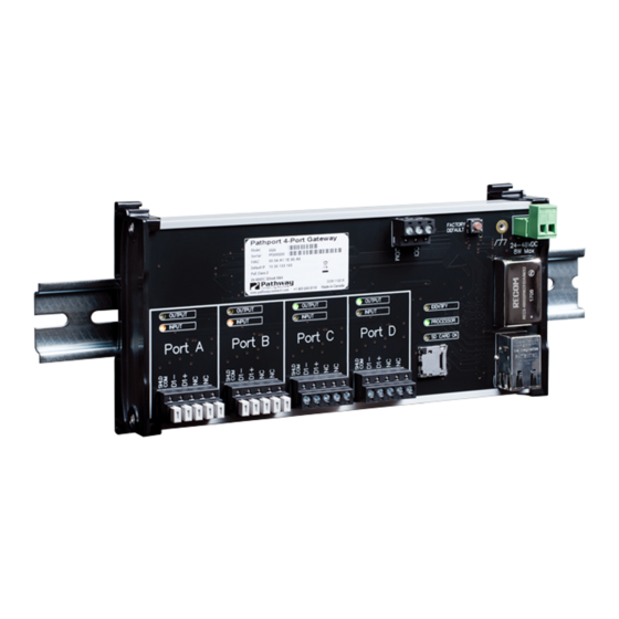
The Pathport® DIN-mount 4-Port Gateway (PWPP DIN P4)
provides the full functionality of other Pathport gateways
in a compact, DIN-rail mountable form factor.
System integrators can now easily put fully customized
universes of DMX where they are needed. Ideal for use in
NEMA enclosures. Fully compatible with DIN interfaces
(PWINF).
CONNECTIONS
The Pathport PWPP DIN P4 features terminal strips that can
be removed from the card to facilitate easy wiring installation or
replacement. Make the following connections, WITH THE POWER
TURNED OFF.
POWER
The PWPP DIN P4 is designed to run on either Power-over-Ethernet
(PoE), or on an auxiliary power supply providing between 24 and 48
volts DC. The gateway is Class 2 PoE and will draw up to 8 Watts.
If an auxiliary supply is used, observe the correct polarity when
wiring the power IN terminal plug. The earth ground terminal
must be connected to the enclosure's chassis or electrical ground
terminal to ensure EMC compliance.
DMX512
DMX connections consist of a shield and data pair. Connect DATA+
and DATA- to D1+ and D1-. Observe the same polarity convention
throughout the system. Connect the cable shield or common to the
SHLD COM terminal.
NETWORK
All network wiring should follow standard Ethernet rules and be
installed by a qualified person. As part of the installation, all wiring
should be certified under the TIA/EIA-568 standard.
CONTACT CLOSURE INTERFACE (CCI)
There is a 3-pole terminal connector included for dry contact
closure input. The CCI supports two functions: DMX Hold and RDM
Pause. See the Pathscape Manual for details on how to enable
these functions
OUTPUT
OUTPUT
INPUT
INPUT
Port A
Port B
DMX512 Inputs/Outputs (4)
Pathport DIN-Mount DMX/RDM Ethernet Gateway
PWPP DIN P4
Contact Closure
Input
OUTPUT
OUTPUT
INPUT
INPUT
Port C
Port D
microSD
Card Slot
STATUS INDICATORS
PROCESSOR
RJ45 LEDs
DMX INPUT
DMX OUTPUT
IDENTIFY
SD CARD OK
Factory Default/
Reset Button
FACTORY
Power In (If PoE not in use):
DEFAULT
24-48 VDC, 7W Supply required.
–
+
24–48VDC
Use PWPWR DIN TERM 100W
7W Max
48VDC or equal.
Connect Earth ground to to
improve EMC compliance
IDENTIFY
PROCESSOR
SD CARD OK
Ethernet connector
Manual
Green. Steady heartbeat indicates processor is
running; off indicates no power.
The RJ45 Ethernet jack has two green LEDs.
One will glow steady when the link is up and
the other will flash with activity.
Amber. Steady glow indicates port is receiving
active DMX. Blinking indicates no incoming
DMX signal. Off indicates Port is Disabled.
Steady
glow
Green.
transmitting DMX. Blinking indicates no DMX
output. Off indicates Port is Disabled.
Blue. Blinks when identify is active.
Green. Steady glow indicates microSD card is
present. Off indicates no SD card present or
SD card error/cannot be read.
Fastening Mechanism designed
for 35 x 7.5mm DIN Rail
DIN rail release lever
Use large flat-head screwdriver or
similar tool to gently pry lever away
from DIN rail to release
Female RJ45
indicates
port
is
03/08/22
Advertisement

Related Manuals for Pathport PWPP DIN P4


Summary of Contents for Pathport PWPP DIN P4
- Page 1 RJ45 LEDs The RJ45 Ethernet jack has two green LEDs. The PWPP DIN P4 is designed to run on either Power-over-Ethernet One will glow steady when the link is up and (PoE), or on an auxiliary power supply providing between 24 and 48 the other will flash with activity.
- Page 2 PWPP DIN P4. • The system is now ready for testing. • To remove the PWPP DIN P4 from the DIN rail, use a flathead Once checked, you may select the network protocol(s) to receive. screwdriver to gently pry the hooked foot on the end caps of the device away from the DIN rail.
- Page 3 Pathport DIN-Mount DMX/RDM Ethernet Gateway Manual PWPP DIN P4 ELECTRICAL INFORMATION • PoE-powered Class 2 device, 7W max power consumption • Auxiliary input voltage, 24-48V • 3000V isolation between DMX ports • 60V protection on each port • 10Mb TCP/IP connection COMPLIANCE •...
Need help?
Do you have a question about the PWPP DIN P4 and is the answer not in the manual?
Questions and answers