
Related Manuals for Actel IGLOO PLUS Starter Kit


Summary of Contents for Actel IGLOO PLUS Starter Kit
- Page 1 IGLOO PLUS Starter Kit User’s Guide Downloaded from Elcodis.com electronic components distributor...
- Page 2 No part of this document may be copied or reproduced in any form or by any means without prior written consent of Actel. Actel makes no warranties with respect to this documentation and disclaims any implied warranties of merchantability or fitness for a particular purpose. Information in this document is subject to change without notice.
-
Page 3: Table Of Contents
Introduction ........5 IGLOO PLUS Starter Kit Contents ....... . . 5 1 Board Components and Settings . - Page 4 Actel Technical Support ........
-
Page 5: Introduction
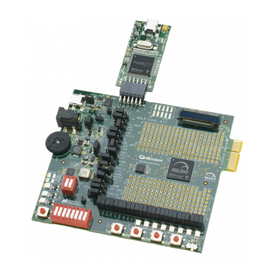
This development kit includes an on-board programmer and demonstrates the ultra-low power of Actel IGLOO PLUS devices. Table 1 lists the contents of the box. Table 1 · IGLOO PLUS Starter Kit Contents Quantity Contents IGLOO PLUS board with AGLP125 IGLOO PLUS FPGA... - Page 6 Downloaded from Elcodis.com electronic components distributor...
-
Page 7: Board Components And Settings
This evaluation board enables you to measure power consumption (dynamic, static, and Flash*Freeze modes) with the core operating between 1.2 V and 1.5 V. When using the board in conjunction with Actel’s power analysis tools, you will have a clear picture of application power consumption at each stage in your design. In addition, the Libero® Integrated Design Environment (IDE) tool suite now includes power-driven layout (PDL), which can reduce the power consumption of designs up to 30 percent. -
Page 8: Igloo Plus Board Stackup
Figure 1-3 on page 10 show the top (L1) and bottom (L10) silkscreens. The full PCB design layout is provided on the Actel website, on the IGLOO PLUS Starter Kit page: http://www.actel.com/products/hardware/devkits_boards/iglooplus_starter.aspx. To view the PCB design layout files, you can use the Allegro Free Physical Viewer, which can be downloaded from the... - Page 9 IGLOO PLUS Board Stackup Figure 1-2 · IGLOO PLUS Top Silkscreen (L1) IGLOO PLUS Starter Kit User’s Guide Downloaded from Elcodis.com electronic components distributor...
- Page 10 Board Components and Settings Figure 1-3 · IGLOO PLUS Bottom Silkscreen (L10) IGLOO PLUS Starter Kit User’s Guide Downloaded from Elcodis.com electronic components distributor...
-
Page 11: Connectors, Jumpers, And Switch Settings
Pin 1-4 = 2.5 V Pin 2-3 Current measurement header for VCCI_2 Select VCC or VCC_SWEEP for VCCI_0 Pin 1-2 Pin 1-2 = VCC Pin 3-2 = VCC_SWEEP IGLOO PLUS Starter Kit User’s Guide Downloaded from Elcodis.com electronic components distributor... - Page 12 FPGA. J28 = D_SWITCH1 J29 = D_SWITCH2 J30 = D_SWITCH3 J28-J35 Pin 1-2 J31 = D_SWITCH4 J32 = D_SWITCH5 J33 = D_SWITCH6 J34 = D_SWITCH7 J35 = D_SWITCH8 IGLOO PLUS Starter Kit User’s Guide Downloaded from Elcodis.com electronic components distributor...
- Page 13 Contains DIP switches for D_SWITCH[1:8] Push-button switch for system reset PBRESET_N Flash*Freeze: To enable Flash*Freeze mode, SW8 toward ON. In Flash*Freeze mode, current consumption of FPGA goes below 50 μA. IGLOO PLUS Starter Kit User’s Guide Downloaded from Elcodis.com electronic components distributor...
- Page 14 Downloaded from Elcodis.com electronic components distributor...
-
Page 15: Fpga Description
4,608-Bit Blocks FlashROM (bits) Secure (AES) ISP Integrated PLLs in CCCs VersaNet Globals I/O Banks Maximum User I/Os For further information, refer to the IGLOO PLUS datasheet: http://www.actel.com/documents/IGLOOPLUS_DS.pdf IGLOO PLUS Starter Kit User’s Guide Downloaded from Elcodis.com electronic components distributor... -
Page 16: Power And Ground Pins
VCCIB2_3 GND37 GND38 VCCIB2_4 GND39 GND40 GND41 VCCIB3_1 GND42 GND43 VCCIB3_2 GND44 GND45 VCCIB3_3 GND46 GND47 VCCIB3_4 GND48 AGLP125-CSG289 Figure 2-1 · Power and Ground Pins for AGLP125-CSG289 IGLOO PLUS Starter Kit User’s Guide Downloaded from Elcodis.com electronic components distributor... -
Page 17: Bank I/O Signals
TP100 TP100 IO35RSB0 GBB1/IO60RSB0 TP99 TP99 TP123 TP123 AGL_B0_PIN_E10 AGL_B0_PIN_A17 IO36RSB0 GBC0/IO57RSB0 AGL_B0_PIN_B10 AGL_B0_PIN_B16 TP119 TP119 IO37RSB0 GBC1/IO58RSB0 AGLP125-CSG289 Figure 2-2 · Bank 0 I/O Signals for AGLP125-CSG289 IGLOO PLUS Starter Kit User’s Guide Downloaded from Elcodis.com electronic components distributor... - Page 18 AGL_B1_PIN_K13 IO94RSB1 TP16 TP16 AGL_B1_PIN_K14 IO95RSB1 TP30 TP30 AGL_B1_PIN_M16 IO96RSB1 TP18 TP18 AGL_B1_PIN_M15 IO97RSB1 TP41 TP41 AGL_B1_PIN_L15 IO98RSB1 AGLP125-CSG289 Figure 2-3 · Bank 1 I/O Signals for AGLP125-CSG289 IGLOO PLUS Starter Kit User’s Guide Downloaded from Elcodis.com electronic components distributor...
- Page 19 TP177 IO136RSB2 GEA2/IO164RSB2 TP149 TP149 AGL_B2_PIN_N9 IO137RSB2 FF/GEB2/IO163RSB2 IGLOO_FF [6] TP173 TP173 TP136 TP136 AGL_B2_PIN_U8 AGL_B2_PIN_T2 IO138RSB2 GEC2/IO162RSB2 AGLP125-CSG289 Figure 2-4 · Bank 2 I/O Signals for AGLP125-CSG289 IGLOO PLUS Starter Kit User’s Guide Downloaded from Elcodis.com electronic components distributor...
- Page 20 PBRESET_N [6] AGL_B3_PIN_G3 IO198RSB3 AGL_B3_PIN_H5 IO199RSB3 IO200RSB3 AGL_B3_PIN_G5 IO201RSB3 IO202RSB3 AGL_B3_PIN_G4 IO203RSB3 IO204RSB3 IO205RSB3 AGL_B3_PIN_G6 IO206RSB3 AGL_B3_PIN_F6 IO208RSB3 IO210RSB3 AGLP125-CSG289 Figure 2-5 · Bank 3 I/O Signals for AGLP125-CSG289 IGLOO PLUS Starter Kit User’s Guide Downloaded from Elcodis.com electronic components distributor...
-
Page 21: Jtag Pins
SEC 6/6 SEC 6/6 JTAG JTAG VJTAG VJTAG TRST TRST VPUMP VPUMP AGLP125-CSG289 HDR_4PIN HDR_4PIN V3P3 1V5_1V2 VJTAG HDR_3PIN HDR_3PIN HDR_4PIN HDR_4PIN V3P3 VPUMP Figure 2-6 · JTAG Pins IGLOO PLUS Starter Kit User’s Guide Downloaded from Elcodis.com electronic components distributor... -
Page 22: Decaps And Ground Post Schematics
DECAPS FOR I/O BANK0 , BANK1 ,BANK2 & BANK3 VCCI_0 VCCI_1 VCCI_2 VCCI_3 GROUND POST HEADER 1 HEADER 1 HEADER 1 HEADER 1 Figure 2-7 · Schematics for Decaps and Ground Post IGLOO PLUS Starter Kit User’s Guide Downloaded from Elcodis.com electronic components distributor... -
Page 23: Power
R0402 R0402 0.027UF 0.027UF 0.1uF 0.1uF 0.1uF 0.1uF C0402 C0402 SI3407DV SI3407DV 220K 220K R0402 R0402 BAT54 BAT54 ACTIVE INRUSH LIMITER Figure 3-1 · USB Active Inrush Limiter IGLOO PLUS Starter Kit User’s Guide Downloaded from Elcodis.com electronic components distributor... -
Page 24: Power Modes
The ULSICC macro, when enabled, disables the FlashROM, reducing the overall power of the device. Table 3-2 gives a summary of the power modes available with IGLOO PLUS devices in general and is extracted from the “Actel’s Flash*Freeze Technology and Low Power Modes” chapter of the IGLOO PLUS FPGA Fabric User’s Guide.. -
Page 25: Battery
3.3 V 3.3 V VCCI_0 2.5 V VCCI_1 3.3 V -Sweep VCCI_2 VCCI_3 1.5 V -Sweep -Sweep 3.3 V JTAG 3.3 V PUMP Figure 3-3 · Current Measurement Headers IGLOO PLUS Starter Kit User’s Guide Downloaded from Elcodis.com electronic components distributor... -
Page 26: Current Measurement
Figure 3-7 on page Voltage sources can be selected using jumpers or can be selected to sweep between 1.2 V and 1.5 V using the potentiometer on the development board. IGLOO PLUS Starter Kit User’s Guide Downloaded from Elcodis.com electronic components distributor... - Page 27 3.3 V or 2.5 V VCCI_3 3.3 V or 2.5 V 1.5 V 3.3 V JTAG 3.3 V PUMP Figure 3-6 · Current Measurement Headers for Power Rails IGLOO PLUS Starter Kit User’s Guide Downloaded from Elcodis.com electronic components distributor...
- Page 28 4PIN_HEADER 4PIN_HEADER 1V5_1V2 VCC_SWEEP HDR_4PIN HDR_4PIN HDR_3PIN HDR_3PIN V3P3 VCCI_1 VCC_SWEEP 4PIN_HEADER 4PIN_HEADER HDR_4PIN HDR_4PIN HDR_3PIN HDR_3PIN V3P3 VCCI_2 HDR_4PIN HDR_4PIN V3P3 VCCI_3 Figure 3-7 · Power-Up Options IGLOO PLUS Starter Kit User’s Guide Downloaded from Elcodis.com electronic components distributor...
-
Page 29: Operation Of Board Components
The PLL can be configured and instantiated in the FPGA to generate a wide range of clock frequencies. Reference For more information, refer to the IGLOO PLUS Starter Kit website page: http://www.actel.com/products/hardware/devkits_boards/iglooplus_starter.aspx. Schematic Figure 4-1 shows the schematic for the clock oscillator. -
Page 30: Flash*Freeze Mode
FF pin AND user-defined logic. Flash*Freeze management IP can be used in type 2 mode for clock and data management while entering and exiting Flash*Freeze mode. For more information and detailed usage of Flash*Freeze modes, refer to the “Actel’s Flash*Freeze Technology and Low Power Modes” chapter of the IGLOO PLUS FPGA Fabric User’s... - Page 31 Figure 4-4 · Flash*Freeze Mode Type 1 – Controlled by the Flash*Freeze Pin Normal Normal Flash*Freeze Operation Operation Mode Flash*Freeze Pin t = 1 µs t = 1 µs Figure 4-5 · Flash*Freeze Mode Type 1 – Timing Diagram IGLOO PLUS Starter Kit User’s Guide Downloaded from Elcodis.com electronic components distributor...
- Page 32 Operation of Board Components Flash*Freeze Type 2: Control by Dedicated Flash*Freeze Pin and Internal Logic The device can be made to enter Flash*Freeze mode by activating the FF pin together with Actel's Flash*Freeze management IP core or user-defined control logic (Figure 4-6) within the FPGA core.
- Page 33 2. Internal core logic driven by this input buffer will be tied High as long as the device is in Flash*Freeze mode. 3. For bidirectional buffers: Internal core logic driven by the input portion of the bidirectional buffer will be set to the hold state. IGLOO PLUS Starter Kit User’s Guide Downloaded from Elcodis.com...
- Page 34 Flash*Freeze variants can be demonstrated by configuring the I/Os in Designer and using switches as inputs to control the FET LEDs. Refer to the demo design, which provides additional details on demonstrating these Flash*Freeze variants (“IGLOO PLUS Board Demo” on page 51). IGLOO PLUS Starter Kit User’s Guide Downloaded from Elcodis.com electronic components distributor...
- Page 35 Flash*Freeze variants. Refer to the demo design that demonstrates the Flash*Freeze variants with these switches. 3V3_SWITCH1 3V3_SWITCH2 3V3_SWITCH1 3V3_SWITCH2 76SB02ST 76SB02ST Figure 4-9 · Two I/Os Controlled via DIP Switch Toggling High or Low IGLOO PLUS Starter Kit User’s Guide Downloaded from Elcodis.com electronic components distributor...
- Page 36 N TYPE FET V3P3 1.5K 1.5K MOSFET_NTYPE MOSFET_NTYPE Mfg P/N = FDV301N Mfg P/N = FDV301N Manufacturer = FairChild Manufacturer = FairChild FET_N Figure 4-10 · FET LEDs for Debugging IGLOO PLUS Starter Kit User’s Guide Downloaded from Elcodis.com electronic components distributor...
-
Page 37: Push-Button Switches
Figure 4-11 · Push-Button Switches Schematic HDR1X2 HDR1X2 HDR1X2 HDR1X2 SWITCH1 HDR1X2 HDR1X2 SWITCH2 HDR1X2 HDR1X2 SWITCH3 HDR1X2 HDR1X2 SWITCH4 3V3_SWITCH1 [8] Figure 4-12 · Jumper Header Schematic for Push-Button Switches IGLOO PLUS Starter Kit User’s Guide Downloaded from Elcodis.com electronic components distributor... -
Page 38: Dip Switches
D_SWITCH3 [6] HDR1X2 HDR1X2 D_SWITCH4 [6] HDR1X2 HDR1X2 D_SWITCH5 [6] HDR1X2 HDR1X2 D_SWITCH6 [6] HDR1X2 HDR1X2 D_SWITCH7 [6] D_SWITCH8 [6] Figure 4-14 · Jumper Header Schematic for DIP Switches IGLOO PLUS Starter Kit User’s Guide Downloaded from Elcodis.com electronic components distributor... -
Page 39: User Leds
HDR1X2 HDR1X2 LED2 HDR1X2 HDR1X2 LED3 HDR1X2 HDR1X2 LED4 HDR1X2 HDR1X2 LED5 HDR1X2 HDR1X2 LED6 HDR1X2 HDR1X2 LED7 LED8 Figure 4-16 · Jumper Header Schematic for User LEDs IGLOO PLUS Starter Kit User’s Guide Downloaded from Elcodis.com electronic components distributor... -
Page 40: I/O Test Pins
TP55 TP190 TP190 TP259 TP259 TP316 TP316 TP296 TP296 TP56 TP56 TP191 TP191 V3P3 1V5_1V2 TP13 TP13 TP11 TP11 TP12 TP12 Figure 4-18 · I/O Test Pins Schematic IGLOO PLUS Starter Kit User’s Guide Downloaded from Elcodis.com electronic components distributor... -
Page 41: Oled
The demo design included in this kit contains a roulette game that uses the OLED for display and the push-button switch for game control. Additional OLED info is available at the IGLOO PLUS Starter Kit website page: http://www.actel.com/products/hardware/devkits_boards/iglooplus_starter.aspx. V3P3... -
Page 42: Interface Connector
Matting Conn P/N: MEC1-120-02-F-S-EM2 20x2 Edge Fingers Mfr : Samtec Pin No:15 & 16 Should be NC For Matting Connector Polarised Pins Figure 4-20 · Interface Connector Schematic IGLOO PLUS Starter Kit User’s Guide Downloaded from Elcodis.com electronic components distributor... -
Page 43: Usb-To-Uart Interface
COM port and communication settings selected, you can use the HyperTerminal program to communicate with a design running in the IGLOO PLUS FPGA device. Information on the USB-to-UART bridge datasheet and device drivers are available at the IGLOO PLUS Starter Kit website page: http://www.actel.com/products/hardware/devkits_boards/iglooplus_starter.aspx. -
Page 44: Spi Flash
I2C. In the schematics shown in Figure 4-22, either the Winbond or Atmel 2 Mbyte SPI flash will be populated on-board. Winbond and Atmel SPI flash datasheets are available at the IGLOO PLUS Starter Kit website page: http://www.actel.com/products/hardware/devkits_boards/iglooplus_starter.aspx 2 MByte SPI FLASH... -
Page 45: Low-Cost Programming Stick (Lcps)
Figure 4-23 · Low-Cost Programming Stick (LCPS) Note: The LCPS supplied with this kit is intended for use with the IGLOO PLUS Starter Kit. An LCPS supplied for other kits, although electrically and functionally equivalent, may not connect seamlessly with the IGLOO PLUS Starter Kit board. - Page 46 VJTAG TRST VJTAG TRSTB VPUMP VPUMP GND4 GND5 HEADER 6x2/SM HEADER 6x2/SM 6X2 Right Angled Header Mfr P/N :TSW-106-08-T-D-RA Mfr: SAMTEC Figure 4-24 · FPGA Programming Headers Schematic IGLOO PLUS Starter Kit User’s Guide Downloaded from Elcodis.com electronic components distributor...
- Page 47 The LCPS is built on a four-layer PCB with the layers arranged in the following stackup: Top signal layer (Figure Ground plane Power plane Bottom signal layer (Figure 4-26 on page Figure 4-25 · Low-Cost Programming Stick – Top Silkscreen IGLOO PLUS Starter Kit User’s Guide Downloaded from Elcodis.com electronic components distributor...
- Page 48 Operation of Board Components Figure 4-26 · Low-Cost Programming Stick – Bottom Silkscreen IGLOO PLUS Starter Kit User’s Guide Downloaded from Elcodis.com electronic components distributor...
-
Page 49: Programming
Attach a USB cable to the LCPS. This allows a programming data file, in programming database format (*.pdb) or STAPL format (*.stp), to be downloaded via the FlashPro software to the Actel IGLOO PLUS device fitted to the board. - Page 50 Downloaded from Elcodis.com electronic components distributor...
-
Page 51: Igloo Plus Board Demo
During Flash*Freeze mode, the active LEDs will be weakly ON, since they are driven by the weak hold state resistors. Flash*Freeze variants can be demonstrated using the F*F switches and FET LEDs. The IGLOO PLUS demo design RTL and design files are available at the IGLOO PLUS Starter Kit website page: http://www.actel.com/products/hardware/devkits_boards/iglooplus_starter.aspx. Refer to the Quick Start Guide available on the website to run the demo. - Page 52 Name I/O Hold Description Resister Pull FET Switch 1 Enabled Down Drives FET LED D13 directly FET Switch 2 Disabled Down Drives FET LED D14 and D15 directly IGLOO PLUS Starter Kit User’s Guide Downloaded from Elcodis.com electronic components distributor...
- Page 53 Ensure the F*F switch is in the OFF position. Power-on the IGLOO PLUS Starter Kit board using the power supply or USB cable included in the starter kit. Press and release the System Reset button (SW7) to reset the IGLOO PLUS FPGA.
- Page 54 OFF (1) OFF (1) ON (0) ON (0) OFF (0) ON (1) OPEN (1) OPEN (1) OFF (1) OFF (1) OFF (1) ON (0) ON (1) ON (1) IGLOO PLUS Starter Kit User’s Guide Downloaded from Elcodis.com electronic components distributor...
-
Page 55: A Resources
Resources IGLOO PLUS Starter Kit http://www.actel.com/products/hardware/devkits_boards/iglooplus_starter.aspx IGLOO PLUS Overview http://www.actel.com/products/iglooplus/default.aspx IGLOO PLUS Datasheet http://www.actel.com/documents/IGLOOPLUS_DS.pdf IGLOO PLUS FPGA Fabric User’s Guide http://www.actel.com/documents/IGLOOPLUS_UG.pdf Libero IDE Design Software http://www.actel.com/products/software/libero/default.aspx [BOOK TITLE IS A VARIABLE] [BOOK SUBTITLE IS A VARIABLE] Downloaded from Elcodis.com electronic components distributor... - Page 56 Downloaded from Elcodis.com electronic components distributor...
- Page 57 Fax, from anywhere in the world 650.318.8044 Actel Customer Technical Support Center Actel staffs its Customer Technical Support Center with highly skilled engineers who can help answer your hardware, software, and design questions. The Customer Technical Support Center spends a great deal of time creating application notes and answers to FAQs.
- Page 58 ., Pacific Time, Monday through Friday. The Technical Support numbers are: 650.318.4460 800.262.1060 Customers needing assistance outside the US time zones can either contact technical support via email (tech@actel.com) or contact a local sales office. Sales office listings can be found at www.actel.com/contact/offices/index.html.
- Page 59 LEDs 39 USB-to-UART 43 switches hardware DIP 38 components 7 push-button 37 settings 11 I/O test pins 40 IGLOO PLUS Starter Kit board technical support 57 photograph 5 IGLOO PLUS Starter Kit User’s Guide Downloaded from Elcodis.com electronic components distributor...
- Page 60 Index submit case online 57 User LEDs 39 USB-to-UART web-based technical support 57 interface 43 IGLOO PLUS Starter Kit User’s Guide Downloaded from Elcodis.com electronic components distributor...
- Page 61 Downloaded from Elcodis.com electronic components distributor...
- Page 62 Phone 650.318.4200 • Fax 650.318.4600 • Customer Service: 650.318.1010 • Customer Applications Center: 800.262.1060 Actel Europe Ltd. • River Court, Meadows Business Park • Station Approach, Blackwater • Camberley Surrey GU17 9AB • United Kingdom Phone +44 (0) 1276 609 300 • Fax +44 (0) 1276 607 540 Actel Japan •...
Need help?
Do you have a question about the IGLOO PLUS Starter Kit and is the answer not in the manual?
Questions and answers