Advertisement
Quick Links
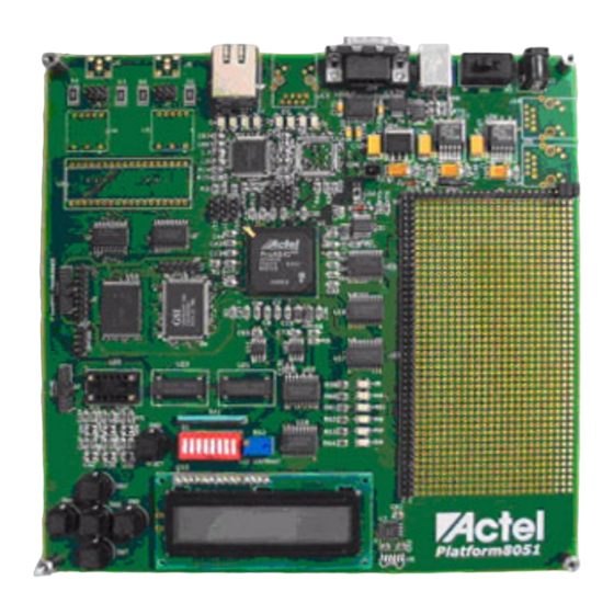
Core429 Daughter Board
Programming and Testing Procedure v1.1
This guide provides instructions to program the Platform8051 Development Board and test the
Core429 Daughter Board.
Note: Steps 1-31 can be performed once because only one correctly programmed Platform8051
Board is needed to test multiple Core429 Daughter Boards. Step 32 and above are
required to test each Core429 Daughter Board.
Jan 2005
©
2005 Actel Corporation
Core429 PCB
Programming and Testing Procedure
50400031-1
v1.1
1
Advertisement

Subscribe to Our Youtube Channel
Related Manuals for Actel Core429


Summary of Contents for Actel Core429
- Page 1 This guide provides instructions to program the Platform8051 Development Board and test the Core429 Daughter Board. Note: Steps 1-31 can be performed once because only one correctly programmed Platform8051 Board is needed to test multiple Core429 Daughter Boards. Step 32 and above are required to test each Core429 Daughter Board. 50400031-1 Jan 2005 ©...
- Page 2 FlashPro Lite Programmer. 2. Prepare the PC a. Install FlashPro 3.2 or later. A FlashPro 3.2 CD can be found in the Core429 Devkit, insert the CD and follow the on-screen instructions. b. Install FS2 debugger. A FS2 ISA-Actel51 Debugger CD can be found in the Core429 Devkit, insert the CD and follow the on-screen instructions.
- Page 3 Core429 PCB Programming and Testing Procedure v1.1 3. Install jumper “J1” (if not already installed). 50400031-1 Jan 2005 © 2005 Actel Corporation...
- Page 4 Core429 PCB Programming and Testing Procedure v1.1 4. Peel off the plastic cover on the LCD (if not already removed). 50400031-1 Jan 2005 © 2005 Actel Corporation...
- Page 5 Core429 PCB Programming and Testing Procedure v1.1 5. Connect FlashPro Lite (not FlashPro) to the pf8051 board. 6. Connect the FlashPro Lite to the PC’s parallel port. 50400031-1 Jan 2005 © 2005 Actel Corporation...
- Page 6 Core429 PCB Programming and Testing Procedure v1.1 7. Connect the power supply to the pf8051 board (ensure the switch is off). 50400031-1 Jan 2005 © 2005 Actel Corporation...
- Page 7 Core429 PCB Programming and Testing Procedure v1.1 8. Set the DIPSWITCH. There are 8 switches on the DIPSWITCH: a. 1-6 should be set to “closed’, push the small button to the side opposite the one marked “open” b. 7-8 should be set to “open”, push the small button to the side marked “open”...
- Page 8 Core429 PCB Programming and Testing Procedure v1.1 9. Turn on the power by sliding the power switch (SW1) to the left. 50400031-1 Jan 2005 © 2005 Actel Corporation...
- Page 9 Core429 PCB Programming and Testing Procedure v1.1 10. Run the FlashPro software on the PC. 11. Select: “File -> Connect…” 50400031-1 Jan 2005 © 2005 Actel Corporation...
- Page 10 Core429 PCB Programming and Testing Procedure v1.1 12. Click “Connect”. 13. Select “File -> Analyze Chain”. Check that APA600 appears in the above window. 50400031-1 Jan 2005 © 2005 Actel Corporation...
- Page 11 Core429 PCB Programming and Testing Procedure v1.1 14. Select “File -> Open STAPL File”. 15. Browse to “<CD Drive>:/ core429_devkit_2.0/Core429_Demonstration/FPGA_design/bitstream/”, select “core429.stp” and click “Open”. 50400031-1 Jan 2005 © 2005 Actel Corporation...
- Page 12 Core429 PCB Programming and Testing Procedure v1.1 16. Select “Action -> PROGRAM”. 50400031-1 Jan 2005 © 2005 Actel Corporation...
- Page 13 Core429 PCB Programming and Testing Procedure v1.1 17. Click the “Play” button circled below: 18. Click on “Execute”. 50400031-1 Jan 2005 © 2005 Actel Corporation...
- Page 14 Core429 PCB Programming and Testing Procedure v1.1 19. Wait until the message “PASSED, EXIT 0” appears at the bottom of the window (approximately 10 minutes). 20. Select “File -> Exit”. 50400031-1 Jan 2005 © 2005 Actel Corporation...
- Page 15 Core429 PCB Programming and Testing Procedure v1.1 21. Start “FS2 Debugger” on the PC by clicking “Start -> Programs -> FS2 -> FS2 ISA-Actel51 Debugger”. (If Debugger fails to start, exit program, power cycle the PF8051 board, then start FS2 Debugger again) 22.
- Page 16 Core429 PCB Programming and Testing Procedure v1.1 23. Browse to “<CD Drive>:/ Core429_devkit_2.0/Core429_Demonstration/demo_software/”, select “demo.hex” and click “Open” then “OK”. 50400031-1 Jan 2005 © 2005 Actel Corporation...
- Page 17 Core429 PCB Programming and Testing Procedure v1.1 24. Wait for about 30 seconds and click on “Go”, the message “Running” should appear in green at the bottom of the window. 50400031-1 Jan 2005 © 2005 Actel Corporation...
- Page 18 Core429 PCB Programming and Testing Procedure v1.1 25. Adjust the screw on the LCD contrast control (circled below) until the characters on the LCD are clear. 50400031-1 Jan 2005 © 2005 Actel Corporation...
- Page 19 Core429 PCB Programming and Testing Procedure v1.1 26. Set the DIPSWITCH There are 8 switches on the DIPSWITCH: a. 1 should be set to “open”, push the small button to the side marked “open” b. 2-6 should be set to “closed’, push the small button to the side opposite the one marked “open”...
- Page 20 Core429 PCB Programming and Testing Procedure v1.1 27. Press the Reset button once and wait for about 15 seconds. 50400031-1 Jan 2005 © 2005 Actel Corporation...
- Page 21 Core429 PCB Programming and Testing Procedure v1.1 28. In FS2 Debugger, Select “File -> Exit”. 50400031-1 Jan 2005 © 2005 Actel Corporation...
- Page 22 Core429 PCB Programming and Testing Procedure v1.1 29. Turn off the PF8051 board by sliding the switch below to the right. 50400031-1 Jan 2005 © 2005 Actel Corporation...
- Page 23 Core429 PCB Programming and Testing Procedure v1.1 30. Disconnect the FlashPro Lite from the PF8051 Board. 50400031-1 Jan 2005 © 2005 Actel Corporation...
- Page 24 Core429 PCB Programming and Testing Procedure v1.1 31. Set the DIPSWITCH There are 8 switches on the DIPSWITCH: a. 1-8 should be set to “closed”, push the small button to the side opposite the one marked “open” 50400031-1 Jan 2005 ©...
- Page 25 Core429 PCB Programming and Testing Procedure v1.1 32. Install Jumper (J1) on the Core429 Daughter Board (circled below): 50400031-1 Jan 2005 © 2005 Actel Corporation...
- Page 26 Core429 PCB Programming and Testing Procedure v1.1 33. Install Jumper (J3) such that the top two pins (2 & 3) are connected leaving the bottom most pin (1) unconnected. 50400031-1 Jan 2005 © 2005 Actel Corporation...
- Page 27 Core429 PCB Programming and Testing Procedure v1.1 34. Install Jumpers J20 and J21 (circled below): 50400031-1 Jan 2005 © 2005 Actel Corporation...
- Page 28 Core429 PCB Programming and Testing Procedure v1.1 35. Install Jumper (J22) (circled below): 50400031-1 Jan 2005 © 2005 Actel Corporation...
- Page 29 36. Attach the Core429 Daughter Board (J2) to the PF8051 Board (J23). Note: Ensure that pin 1 of the Core429 Daughter Board connects to pin 1 on the PF8051 connector (J23) (See below and picture on following page) PIN 1 on J23...
- Page 30 Core429 PCB Programming and Testing Procedure v1.1 50400031-1 Jan 2005 © 2005 Actel Corporation...
- Page 31 Core429 PCB Programming and Testing Procedure v1.1 37. Attach the two DB9 cables. a. Channel 0 connects to Channel 1 b. Channel 2 connects to Channel 3 hannel 0 hannel 1 Channel 2 Channel 3 50400031-1 Jan 2005 © 2005 Actel Corporation...
- Page 32 Core429 PCB Programming and Testing Procedure v1.1 38. Turn on the power by sliding the power switch (SW1) to the left. Note: If the LCD remains blank after the power has been turned on: a. Turn off the board power (SW1).
- Page 33 Core429 PCB Programming and Testing Procedure v1.1 39. Hold down the Reset button (SW2) and the UP button (SW3) on the keypad. While holding down the UP button (SW3), Release the Reset button (SW2). Keep the UP button (SW3) depressed until “Test Mode” is displayed on the LCD.
- Page 34 41. Record the test results and turn off the board power by sliding SW1 to the right. 42. Unplug the two DB9 cables from the Core429 Daughter Board and disconnect the Core429 Daughter Board from the Platform8051 Board. 43. Proceed to Step 32 to test another Core429 Daughter Board.
Need help?
Do you have a question about the Core429 and is the answer not in the manual?
Questions and answers