
Subscribe to Our Youtube Channel
Related Manuals for unicraft PG-E Series


Summary of Contents for unicraft PG-E Series
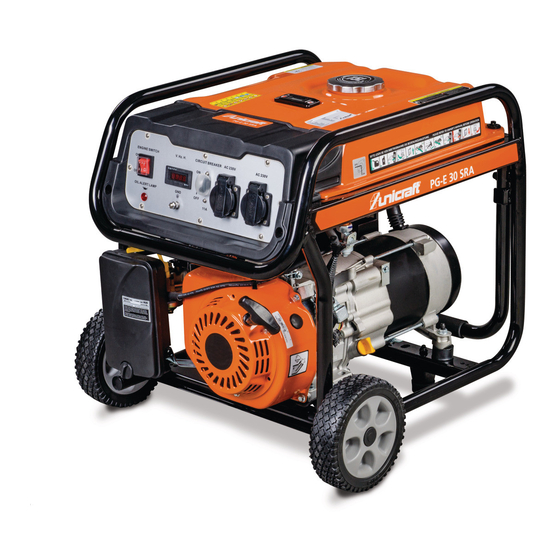
- Page 1 Operating Instructions Generator PG-E 30 SRA, PG-E 40 SRA PG-E 60 SEA, PG-E 90 SEA PG-E 80 TEA, PG-E 100 TEA PG-E 80 TEA...
-
Page 2: Table Of Contents
7.2 Mounting ............11 Fax: 0049 (0) 951 96555 - 55 8 Start-up..............12 8.1 Before starting ..........13 E-Mail: info@unicraft.de 8.2 Starting the generator ........14 Internet: www.unicraft.de 8.3 Operation ............15 8.4 Switching off the generator ....... 16 9 Care, maintenance and repair ......16 9.1 Care by cleaning.......... -
Page 3: Introduction
Fax: 0049 (0) 951 96555-111 E-Mail: service@stuermer-maschinen.de DANGER! Internet: www.unicraft.de This combination of symbol and signal words indi- cates an imminently dangerous situation which may Spare part orders: lead to death or severe injuries if they are not Fax: 0049 (0) 951 96555-119 avoided. -
Page 4: Obligations Of The Operating Company
Safety conditions at the place of use of the machine. These must be implemented in the form of opera- CAUTION! ting instructions for the operation of the machine. This combination of symbol and signal words indi- - During the entire period of use of the machine, the cates a possibly dangerous situation which may lead operator must check whether the operating instruc- to minor or light injuries if they are not avoided... -
Page 5: Personal Protective Equipment
Safety Operator: 2.5 General safety regulations The operator is instructed by the operating company about the assigned tasks and possible risks in case of - Operate the generator ONLY outdoors, sufficiently improper behaviour. Any tasks which need to be perfor- distant from windows, doors and fume cupboards. -
Page 6: Safety Labels On The Generator
Intended Use - Do not run the machine in rooms with a potentially explosive atmosphere. - In an emergency, do not use water to extinguish fi- res, only special safety systems (powder fire extin- guishers, etc.). - If it is necessary to work next to the machine, it is necessary to use hearing protection (headphones, ear protectors, etc.). -
Page 7: Technical Data
Technical Data Technical Data Model PG-E 60 PG-E 80 TEA 4.1 Table Voltage 230 V 230V/400 V Model PG-E 30 PG-E 40 Emergency output 5,5 kW 2,5 kW LTP 230V Voltage 230 V 230 V Continuous output 5,0 kW 2,3 kW Emergency output 2,8 kW 3,8 kW... -
Page 8: Type Plate
Transport, packaging, storage Transport, packaging, storage Model PG-E 90 SEA Voltage 230 V Delivery Apparent power LTP 230V 8,5 VA Check the generator on delivery for any visible transpor- Active power LTP 230V 8,2 kW tation damage. If you notice any damage to the device please report this immediately to the carrier or dealer. - Page 9 Transport, packaging, storage Packaging Step 1: Remove all gasoline from the fuel tank. Start and run ethe motor until motor stops from lack of fuel. All used packaging materials and packaging aids are re- cyclable and should be taken to a materials recycling de- Step 2: While motor is still warm, drain oil from crank- pot to be disposed of.
-
Page 10: Description Of The Device
Description of the device Description of the device Illustrations in these operating instructions may de- viate from the original. Fig. 5: Control panel PG-E 40 SRA (top) and PG-E 80 TEA (down) 1 ONN/OFF switch; Motor START switch 2 Display voltage, frequency, operating hours 3 Fuse switch 4 Oil control lamp 5 Ground connection... -
Page 11: Mounting And Set-Up
Mounting and Set-up Mounting and Set-up Step 3: Insert an M6 bolt through the rubber bumper and insert an M8 bolt through the bottom of the bum- per bracket. Secure the bolt with an M8 flange nut. Use protective gloves! Wear safety boots! Wear protective clothes! CAUTION! -
Page 12: Start-Up
Start-up Start-up WARNING! Danger of life! Failure to observe the following rules entails a risk of injury for the operator and other persons. - The operator must not work under the influence of drugs, alcohol or medication and in case of tired- ness or if suffering from an illness that impairs con- centration. -
Page 13: Before Starting
Start-up NOTE! CAUTION! Before you put the generator into operation for the Do not come into contact with the acid and do not first time, observe the following points. smoke or use open fire: the vapours emitted by the battery are highly flammable! Keep the battery acid - Make sure that the generator stands on a level, ho- out of the reach of children. -
Page 14: Starting The Generator
Start-up Max. fill level (red) Fuel gauge Tank cap Max fill level (red) empty full Fig. 14: ONN/OFF switch Fuel gauge Step 2: Turn fuel switch to “ON” position. Fig. 12: Petrol fill level 8.2 Starting the generator The motor is equipped with a low oil level sensor that au- tomatically shuts down the motor when the oil level drops below a certain level. -
Page 15: Operation
Start-up For electric start, turn and hold key in start switch 8.3 Operation to “start” position until generator starts.To pro- long the life of starter components, DO NOT hold key in “start” position for more than 15 seconds, ATTENTION! and pause for at least 1 minute between starting attempts. -
Page 16: Switching Off The Generator
Care, maintenance and repair Care, maintenance and repair ATTENTION! The generator should be started at least once every ATTENTION! seven days and be allowed to run at least 30 minu- tes. If this cannot be done and the unit must be sto- - All cleaning, care, maintenance and repair work red for more than 30 days, use the following may only be carried out with the generator switched... -
Page 17: Maintenance And Repair
Care, maintenance and repair 9.2 Maintenance and repair 9.4 Changing the motor oil Change the oil after the first five hours of operation, then every 25 hours thereafter. CAUTION! If running this unit under dirty or dusty conditions, or in Maintenance and repair works must only be per- extremely hot weather, change the oil more often.. -
Page 18: Replacing The Spark Plug
Care, maintenance and repair 9.5 Replacing the spark plug 9.7 Air filter Use spark plug F6TC, BPR4ES or Champioin The motor will not run properly and may be damaged if RN14YC.Replace the plug once each year. This will help using a dirty air filter. Replace the air filter once a year. the motor start easier and run better. -
Page 19: Disposal, Recycling Of Used Devices
Disposal, recycling of used devices 10 Disposal, recycling of used devices 11.1 Ordering spare parts The spare parts may be purchased with the authorised Please take care in your own interest and in the interest dealer. of the environment that all component parts of the ma- chine are only disposed of in the intended and permitted Indicate the following basic information for requests or way. -
Page 20: Spare Parts Drawings
Spare parts 11.2 Spare parts drawings In case of service, the following drawing shall help to identify the necessary spare parts. If necessary, send a copy of the parts drawing with the marked components to your authorised dealer. Spare parts drawing PG-E 30 SRA - Complete assembly Fig. - Page 21 Spare parts Spare parts drawing 1: PG-E 30 SRA Spare parts drawing 2: PG-E 30 SRA Fig. 23: Spare parts drawing 2 and Spare parts drawing 2 PG-E 30 SRA PG-E-Series | Version 2.08...
- Page 22 Spare parts Spare parts drawing 3: PG-E 30 SRA Fig. 24: Spare parts drawing 3 PG-E 30 SRA PG-E-Series | Version 2.08...
- Page 23 Spare parts Spare parts drawing 4: PG-E 30 SRA Fig. 25: Spare parts drawing 4 PG-E 30 SRA PG-E-Series | Version 2.08...
- Page 24 Spare parts Spare parts drawing 5: PG-E 30 SRA Fig. 26: Spare parts drawing 5 PG-E 30 SRA PG-E-Series | Version 2.08...
- Page 25 Spare parts Spare parts drawing PG-E 40 SRA - complete assembly Fig. 27: Spare parts drawing PG-E 40 SRA PG-E-Series | Version 2.08...
- Page 26 Spare parts Spare parts drawing 1: PG-E 40 SRA Spare parts drawing 2: PG-E 40 SRA Fig. 28: Spare parts drawing 1 and Spare parts drawing 2 PG-E 40 SRA PG-E-Series | Version 2.08...
- Page 27 Spare parts Spare parts drawing 3: PG-E 40 SRA Fig. 29: Spare parts drawing 3 PG-E 40 SRA PG-E-Series | Version 2.08...
- Page 28 Spare parts Spare parts drawing 4: PG-E 40 SRA Fig. 30: Spare parts drawing 4 PG-E 40 SRA PG-E-Series | Version 2.08...
- Page 29 Spare parts Spare parts drawing 5: PG-E 40 SRA Fig. 31: Spare parts drawing 5 PG-E 40 SRA PG-E-Series | Version 2.08...
- Page 30 Spare parts Spare parts drawing PG-E 60 SEA , PG-E 80 TEA and PG-E 90 SEA - Complete assembly Fig. 32: Spare parts drawing PG-E 60 SEA, PG-E 80 TEA and PG-E 90 SEA - complete assembly PG-E-Series | Version 2.08...
- Page 31 Spare parts Spare parts drawing 1: PG-E 60 SEA , PG-E 80 TEA and PG-E 90 SEA Spare parts drawing 2: PG-E 60 SEA , PG-E 80 TEA and PG-E 90 SEA Fig. 33: Spare parts drawing 1 und Spare parts drawing 2 PG-E 60 SEA, PG-E 80 TEA and PG-E 90 SEA PG-E-Series | Version 2.08...
- Page 32 Spare parts Spare parts drawing 3: PG-E 60 SEA , PG-E 80 TEA and PG-E 90 SEA Fig. 34: Spare parts drawing 3 PG-E 60 SEA, PG-E 80 TEA and PG-E 90 SEA PG-E-Series | Version 2.08...
- Page 33 Spare parts Spare parts drawing 4: PG-E 60 SEA , PG-E 80 TEA and PG-E 90 SEA Fig. 35: Spare parts drawing 4 PG-E 60 SEA, PG-E 80 TEA and PG-E 90 SEA PG-E-Series | Version 2.08...
- Page 34 Spare parts Spare parts drawing 5: PG-E 60 SEA , PG-E 80 TEA and PG-E 90 SEA Fig. 36: Spare parts drawing 5 PG-E 60 SEA, PG-E 80 TEA and PG-E 90 SEA PG-E-Series | Version 2.08...
- Page 35 Spare parts Spare parts drawing 1: PG-E 100 TEA - Complete assembly Fig. 37: Spare parts drawing 1 PG-E 100 TEA - Complete assembly PG-E-Series | Version 2.08...
- Page 36 Spare parts Spare parts drawing 2: PG-E 100 TEA Fig. 38: Spare parts drawing 2 PG-E 100 TEA PG-E-Series | Version 2.08...
- Page 37 Spare parts Spare parts drawing 3: PG-E 100 TEA Fig. 39: Spare parts drawing 3 PG-E 100 TEA PG-E-Series | Version 2.08...
- Page 38 Spare parts Spare parts drawing 4: PG-E 100 TEA Fig. 40: Spare parts drawing 4 PG-E 100 TEA PG-E-Series | Version 2.08...
- Page 39 Spare parts Spare parts drawing 5: PG-E 100 TEA Fig. 41: Spare parts drawing 5 PG-E 100 TEA PG-E-Series | Version 2.08...
-
Page 40: Electrical Circuit Diagrams
Electrical Circuit Diagrams 12 Electrical Circuit Diagrams Fig. 42: Electrical circuit diagrams PG-E 30 SRA (above) and PG-E 40 SRA (below) PG-E-Series | Version 2.08... - Page 41 Electrical Circuit Diagrams Fig. 43: Electrical circuit diagrams PG-E 60 SEA (above) and PG-E 80 TEA (below) PG-E-Series | Version 2.08...
- Page 42 Electrical Circuit Diagrams Abb. 44: Electrical circuit diagram PG-E 90 SEA PG-E-Series | Version 2.08...
- Page 43 Electrical Circuit Diagrams Fig. 45: Electrical circuit diagram PG-E 100 TEA PG-E-Series | Version 2.08...
-
Page 44: Ec Declaration Of Conformity
According to machine directive 2006/42/EC Annex II 1.A Manufacturer/distributing company: Stürmer Maschinen GmbH Dr.-Robert-Pfleger-Str. 26 D-96103 Hallstadt herewith declares that the following product Unicraft® Werkstatttechnik Product group: Machine type: Generator Designation of the machine *: Item number: PG-E 30 SRA... - Page 45 Notes 14 Notes PG-E-Series | Version 2.08...
- Page 46 www.unicraft.de...
Need help?
Do you have a question about the PG-E Series and is the answer not in the manual?
Questions and answers