
Related Manuals for Jumbuck Astro 4


Summary of Contents for Jumbuck Astro 4
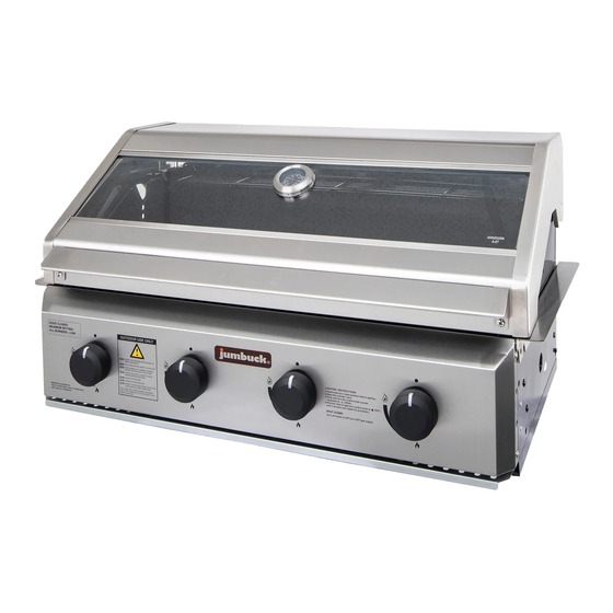
- Page 1 Astro Built Large glass viewing window Front Removable Grease Tray ● 900(L) x 540(W) x 460(H) mm...
- Page 2 BBQ ASSEMBLY & OPERATION INSTRUCTIONS 4 BURNER BULIT IN – MODEL SYGP 4BB...
- Page 9 2 Warming rack 3 Cooking grill 4 Hotplate 1 Hood 6 Firebox 7 Firebox side panel 8 Firebox side panel 5 Firebox rear panel - left - right 9 Flame tamer X 2 12 Control knob X 4 10 Support plate 11 Support plate - left - right...
- Page 10 Hardware Pack Description Image M6x10 Screws ( Silver ) M5x10 Screws ( Black ) M5 Flat Washer ( Black ) M5 Nuts ( Black ) M8x20 Hinge Pin R pin Screwdriver...
- Page 11 NOTE: - Always wear gloves during assembly of this BBQ. - Assemble the BBQ on a flat level surface STEP 1 Assemble the ' Support plate-left' (10) 1pc & ' Support plate-right' (11) 1pc to the 'Firebox'(6) using Screw (A) 8pcs as shown. STEP 2 Assemble the 'Fire box side panel - left' (7) and 'Firebox side panel - right' (8) to the 'Firebox' (6) using Screw (B) 6pcs and Flat washer (C) 6pcs as shown.
- Page 12 STEP 3 Assemble the 'Fire box rear panel' (5) to the 'Firebox'(6) using Screw (B) 7pcs, Flat washer © 7pcs and nut (D) 4pcs as shown. STEP 4 Assemble the 'hood' (1) to the 'firebox' (6) using'Hinge pin'(E) 2pcs and'R pin'(F) 2pcs as shown.
- Page 13 STEP 5 Put the 'Flame tamer' (9) 2pcs into the fire box as shown. NOTE: Flame tamers should be located under the cooking grill. STEP 6 Put the'Hotplate'(4) 1pc,'Cooking grill'(3) 1pc and'Warming rack'(2) 1pc into the firebox as shown.
- Page 14 STEP 7 Insert the Grease tray (13) into the firebox as shown. STEP 8 Assemble the 'Control knob' (12) 4pcs to the 'Firebox' as shown.
- Page 15 STEP 9 Your BBQ is now fully assembled.
-
Page 18: Installation
INSTALLATION CUT OUT DIMENSIONS The cut out must be made from non-combustible material only. 400mm 110mm x 110mm hole for hose access 160mm min. 505mm 220mm The 400mm tall, non-combustible rear splashback is not necessary provided there is no combustible material within 500mm of the rear of the BBQ. If the BBQ is supplied with a duplicate data label, apply this label in the immediate vicinity of the BBQ in an easily accessible area. - Page 29 How to replace the battery in the LED Knobs STEP 1 Ensure the knob is in the OFF position, then gently pull the LED knob straight out from the control panel. STEP 2 Exchange the battery as shown below. First loosen the screw, then remove the battery contact and battery, replace the battery taking note of the orientation shown below.
- Page 30 How to replace the glass in hood Note: Always wear gloves during replacement of the hood glass STEP 1 Remove the temperature gauge as shown. STEP 2 Using a screwdriver loosen the two side 'Glass retaining brackets'as shown. Glass fixed panel...
- Page 31 STEP 3 Move the glass panel to the left side of the BBQ hood, as seen in picture 1. The glass can now be lifted and carefully removed, as seen in picture 2 Picture 1 Picture 2 STEP 4 Remove the stainless steel edging as shown. Stainless steel bar...
- Page 32 STEP 5 Remove silicone seal as shown. Silicone seal STEP 6 After disposing of the old glass correctly, the new glass panel can be installed. Place the new silicone seal around the edges of the glass as shown. Silicone seal...
- Page 33 STEP 7 Assemble the stainless steel edging over the silicone seal as shown. Stainless steel bar STEP 8 Carefully place the left side of the glass panel into the hood before lowering the right side in, as seen in picture one. Then move the glass panel to the right until it is in the centre of the hood.
- Page 34 STEP 9 Using a screwdriver replace the two side'Glass fixing brackets'as shown using the M6 Screws (4pcs) Glass fixed panel STEP 10 Assemble the temperature gauge on the hood as shown. Note: Please do not overtighten the temperature gauge nut.
- Page 35 Thank you for purchasing one of our quality Jumbuck products. Your Jumbuck product is covered against defects for a period of 12 months for parts and labour, repair or replacement. This warranty excludes surface rust and damage caused by abuse or neglect.
- Page 36 Removal or re-installation costs. This If you experience any technical issues with warranty does not cover costs for your Jumbuck product, in the first instance transit nor in home service. review the instruction manual or call the warranty service agent below.
Need help?
Do you have a question about the Astro 4 and is the answer not in the manual?
Questions and answers