
Related Manuals for Lauda LRZ 913

Summary of Contents for Lauda LRZ 913
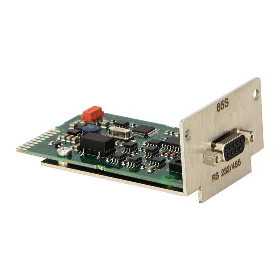
- Page 1 Operation manual Interface module LRZ 913 RS 232/485 module V1R63 Read this manual prior to performing any task!
- Page 2 Manufacturer: LAUDA DR. R. WOBSER GMBH & CO. KG Laudaplatz 1 97922 Lauda-Königshofen Germany Telephone: +49 (0)9343 503-0 Fax: +49 (0)9343 503-222 E-mail: info@lauda.de Internet: https://www.lauda.de Translation of the original operation manual Q4DA-E_13-012, 1, en_US 10/18/2021 © LAUDA 2021 2 / 39...
-
Page 3: Table Of Contents
Read commands............................19 7.2.3 Write commands............................24 7.2.4 Availability of the interface functions....................27 7.2.5 Error messages............................30 Control and automation software..........................32 Maintenance..................................33 Faults....................................34 Alarm.................................... 34 Error..................................... 34 Warning..................................34 Interface module LRZ 913 3 / 39... - Page 4 Decommissioning................................35 Disposal....................................36 Accessories................................... 37 Technical data..................................38 Index..................................... 39 4 / 39 Interface module LRZ 913...
-
Page 5: General
The interface module is an accessory that increases the connections options of LAUDA constant temperature equipment. It may only be installed in con- stant temperature equipment that supports the interface provided. Refer to the chapter "Compatibility” in this operating manual for a list of compatible product lines. -
Page 6: Technical Changes
This operating manual or parts thereof may not be modified, translated or used in any other capacity without the written consent of LAUDA. Violation of this may obligate the violator to the payment of dam- ages. Other claims reserved. -
Page 7: Safety
This operating manual is applicable in combination with the operating manual of the constant temperature equipment in which the interface module is installed. Manuals for LAUDA products are available for download on the LAUDA website: https://www.lauda.de The warnings and safety instructions in this operating manual must be ... -
Page 8: Information About The Interface Module
Use only suitable cables of sufficient length for cable connections. Make sure that the protective screen on the cables and connec- tors complies with EMC regulations. LAUDA recommends using pre- assembled cables. Always lay cables correctly so that they do not pose a tripping hazard. ... -
Page 9: Unpacking
After installing the equipment, dispose of the packaging materials in line with environmental regulations, see Ä “Packaging” on page 36. If you discover any damage on the interface module, contact LAUDA Service immediately, see Ä Chapter 1.6 “Contact LAUDA” on page 6. Interface module LRZ 913... -
Page 10: Device Description
The RS 232/485 module is designed for installation in constant temperature equipment that supports the serial interface. The RS 232/485 interface allows the user to activate constant temperature equipment via the LAUDA command set (for example, control station). Combining the RS 232/485 interface with a Profibus interface is only permitted in conjunction with the Command remote control, whose RS 232/485 interface can be used independently. -
Page 11: Before Starting Up
Always observe safety measures against electrostatic dis- charge. The module installation description essentially applies to all LAUDA constant temperature equipment; the example diagrams here show the installation of an analog module in constant temperature equip- ment from the Variocool product line. - Page 12 Secure the cover to the casing using two M3 x 10 screws. The new interface on the constant temperature equipment is ready for operation. Fig. 5: Securing the cover (schematic dia- gram) 12 / 39 Interface module LRZ 913...
-
Page 13: Using The Module Box
Using the module box You can extend LAUDA constant temperature equipment by two additional module slots using the LiBus module box. The module box is designed for interface modules with a large cover and is connected to constant tem- perature equipment via a vacant LiBus socket. -
Page 14: Commissioning
- Status information is transmitted at the same time as the handshake data. Status information is not included in the operating data, but the signaling requires a 7-wire cable for additional signal lines. 14 / 39 Interface module LRZ 913... - Page 15 D-Sub socket on the PC: Table 2: D-Sub sockets for RS 232 with hardware handshake Constant temperature PC / control station equipment Signal Contact Contact Contact Signal (9‑pin) (9‑pin) (25‑pin) Interface module LRZ 913 15 / 39...
-
Page 16: 6.1.2 Contact Assignment Rs 485
Switch on the constant temperature equipment after installing the new interface. Check whether a software warning appears on the display: Warning SW too old : Please contact LAUDA Service, see Ä Chapter 1.6 “Contact LAUDA” on page 6. No software warning: Operate the constant temperature equip- ... -
Page 17: Operation
Menu Modules Serial interface Fig. 9: RS 232/485 interface menu Master operating unit (Only available for product lines Proline and Integral XT.) Fig. 10: Menu - RS 232/485 interface to Master operating unit Interface module LRZ 913 17 / 39... -
Page 18: Interface Functions
In order to ensure that a request and response are uniquely assigned to one another, commands can only be sent to the constant tem- perature equipment once a response to the previous command has been received. 18 / 39 Interface module LRZ 913... -
Page 19: Read Commands
5 Controlled temperature (internal / external Pt / external analog / external [°C] IN_PV_01 serial) 7 External temperature T (Pt) [°C] IN_PV_03 8 External temperature T (analog input) [°C] IN_PV_04 14 External temperature T (Pt) [°C], IN_PV_13 0.001 °C Interface module LRZ 913 19 / 39... - Page 20 – negative value à device is cooling – positive value à device is heating 13 Controller actuating signal in watts IN_PV_08 – negative value à device is cooling – positive value à device is heating 20 / 39 Interface module LRZ 913...
- Page 21 69 Offset source X for set point: 0 = normal / 1 = external Pt / 2 = external [–] IN_MODE_04 analog / 3 = external serial / 5 = external Ethernet / 6 = external EtherCAT / 7 = external Pt second (only for Integral) Interface module LRZ 913 21 / 39...
- Page 22 98 Contact input 2: 0 = open / 1 = closed [–] IN_DI_02 100 Contact input 3: 0 = open / 1 = closed [–] IN_DI_03 102 Contact output 1: 0 = open / 1 = closed [–] IN_DO_01 22 / 39 Interface module LRZ 913...
- Page 23 122 Solenoid valve, shut off valve 2 [–] VERSION_M_4 (solenoid valve must be present) 124 Pump 0 [–] VERSION_P_0 125 Pump 1 [–] VERSION_P_1 126 Heating system 0 [–] VERSION_H_0 127 Heating system 1 [–] VERSION_H_1 Interface module LRZ 913 23 / 39...
-
Page 24: Write Commands
Table 19: Pump ID Function Unit Command 17 Pump power stage (device-specific, e.g. 1 – 6) [–] OUT_SP_01_XXX 30 Set pressure (for pressure control settings) [bar] OUT_SP_06_X.XX 36 Flow rate control set point [l/min] OUT_SP_09_X.XX 24 / 39 Interface module LRZ 913... - Page 25 66 Control in control variable X: 0 = internal / 1 = external Pt / [–] OUT_MODE_01_X 2 = external analog / 3 = external serial / 5 = external Ethernet / 6 = external EtherCAT / 7 = external Pt second (only for Integral) Interface module LRZ 913 25 / 39...
- Page 26 5 when the constant temperature equipment is switched on. 78 Start programmer [–] RMP_START 79 Pause programmer [–] RMP_PAUSE 80 Continue programmer (after pause) [–] RMP_CONT 81 End programmer [–] RMP_STOP 26 / 39 Interface module LRZ 913...
-
Page 27: 7.2.4 Availability Of The Interface Functions
ü ü ü ü ü ü ü ü ü ü ü ü ü ü ü ü ü ü – – – – – – ü ü * Equipment type as per rating label Interface module LRZ 913 27 / 39... - Page 28 ü ü ü ü ü ü ü ü ü ü ü ü ü ü ü ü ü ü ü ü ü ü ü ü ü ü * Equipment type as per rating label 28 / 39 Interface module LRZ 913...
- Page 29 ü ü ü ü ü ü ü ü ü ü ü ü ü ü ü ü ü ü ü ü ü ü ü ü ü ü * Equipment type as per rating label Interface module LRZ 913 29 / 39...
-
Page 30: 7.2.5 Error Messages
The string ERR_X or ERR_XX is output after an incorrect command. Error Description ERR_2 Incorrect entry (for example, buffer overflow) ERR_3 Wrong command ERR_5 Syntax error in value ERR_6 Impermissible value ERR_8 Module or value not available 30 / 39 Interface module LRZ 913... - Page 31 Analog value not present ERR_35 Automatically configured Not possible to specify set point, programmer is running or ERR_36 has been paused Not possible to start programmer (analog set point value input ERR_37 is ON) Interface module LRZ 913 31 / 39...
-
Page 32: Control And Automation Software
In order to cater for the programming needs of the interface used here, drivers designed specially for LABVIEW ® can be downloaded free of charge from the download area of its LAUDA website: https://www.lauda.de/de/services/download-center/filter/Software 32 / 39... -
Page 33: Maintenance
When using compressed air: Always set a low working pressure to prevent mechanical damage to the connections. If you have any questions about technical modifications, please contact LAUDA Service, see Ä Chapter 1.6 “Contact LAUDA” on page 6. Interface module LRZ 913... -
Page 34: Faults
The RS 232/485 interface recognizes the following error messages: Code * Meaning 501 – 504, 507, 508 Interface module hardware faulty. Contact the LAUDA department. Internal 24 V voltage of the interface module is too low. Internal 24 V voltage of the interface module is too high. -
Page 35: Decommissioning
The storage location must meet the ambient conditions specified in the technical data. If you intend to dispose of the module, please read the information in Ä “Old device” on page 36 first. Interface module LRZ 913 35 / 39... -
Page 36: Disposal
Dispose of the device in accordance with the applicable disposal guidelines in your region. Comply with Directive 2012/19/EU (WEEE Waste of Electrical and Electronic Equipment) if disposing of the product takes place in a member state of the EU. 36 / 39 Interface module LRZ 913... -
Page 37: Accessories
Accessories The following LAUDA accessories are available for assembling the required connection cables: Article Catalog number LiBus module box; Extension of constant temperature equipment by up to two LCZ 9727 interface modules with large cover Pin header, 9-pin D-SUB, soldered EQM 042 Connector shell F. -
Page 38: Technical Data
Maximum relative air humidity 80 % at 31 °C and up to 40 °C, 50 % with linear decrease. Ambient temperature range [°C] 5 – 40 Temperature range for storage [°C] 5 – 50 38 / 39 Interface module LRZ 913... -
Page 39: Index
Warranty ....... . . 6 Interface module LRZ 913 39 / 39... - Page 40 Manufacturer: LAUDA DR. R. WOBSER GMBH & CO. KG ◦ Laudaplatz 1 ◦ 97922 Lauda-Königshofen Telephone: +49 (0)9343 503-0 ◦ Fax: +49 (0)9343 503-222 E-mail: info@lauda.de ◦ Internet: https://www.lauda.de...
Need help?
Do you have a question about the LRZ 913 and is the answer not in the manual?
Questions and answers