Initial Inspection 1 Overview This document outlines the operation and functionality of the 
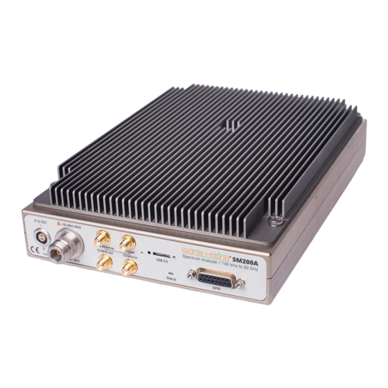
SM200A/B/C and SM435B Signal Hound spectrum monitor and spectrum analyzer. This document will help you understand the capabilities, performance specifications, and features of your SM200 / SM435.
Page 6
Check your package for shipping damage before opening. Your box should contain either a USB 3.0 Vision cable (SM200A/B) or a SFP+ module and 3 meter fiber optic cable (SM200C), a CD- ROM, a GPS antenna, a 12V power supply, and a Signal Hound SM200A/B/C.
Page 7
SM435 may be hot to the touch after prolonged use. Use caution when touching the unit. 2.5 Front Panel 2.5.1 The SM200A/B and SM435B Front Panel The front panel has 8 connectors: 1. 9-16V DC power input: Use the included 12V supply, or a battery that can source 40 watts.
Page 8
9. Status LED: Alternates red/green as commands are processed and sweeps are generated. 2.5.1.1 LED States The possible SM200A/B LED states are OFF, RED, GREEN, and FLASHING. All combinations of device and LED state are described below. Initialization States: OFF – until the power cable and USB cable are both connected.
Page 9
Preparation | Front Panel 1. 9-16V DC power input: Use the included 12V supply, or a battery that can source 40 watts. 2. 50Ω type N RF Input: Do not exceed +20 dBm or damage may occur. 3. SMA GPS antenna port: The GPS antenna (included) may be connected here to discipline the time base and time stamp I/Q data 4.
Page 10
Preparation | Front Panel GREEN – once the device is initialized, the GREEN LED state represents the IDLE state. Operational States: ALTERNATING RED/GREEN – when the device is actively transmitting data. GREEN – Device is idle RED – Indicates a failure. Usually indicates no 10 GbE connection to PC. OFF –...
Page 11
Preparation | Measurement Descriptions The GPIO may be configured as 8 outputs, or 4 outputs and 4 inputs, or 8 inputs. The inputs are automatically read at the end of each sweep, but may be read between sweeps as well. The outputs may be written between sweeps, or configured to generate a pattern during each sweep.
Page 12
Preparation | Measurement Descriptions immediately. Users can choose to continuously retrieve traces or manually request them one at a time with the Single and Continuous buttons found on the Sweep Toolbar. 2.6.1.1 RBW/VBW limitations Low RBW/VBW values increase the working memory footprint of an SM200/SM435 application by increasing the FFT size and increasing buffer sizes for VBW averaging.
Page 13
The Spike application can display amplitude, frequency, and phase vs. time, and display the results through multiple plots. The SM200A can be configured for up to 50 MS/s, the SM200B/SM435B has an additional 250 MS/s option for captures, and the SM200C...
Page 14
Preparation | Measurement Descriptions has additional sample rates of 100 and 200 MS/s available. See the Spike Software manual for further information on using Zero Span analysis. 2.6.3.1 Triggering in Zero Span You can specify an immediate, video, external, or frequency mask trigger (FMT) in zero-span mode.
Understanding the SM-series Hardware | Highlights include video, external, and frequency mask triggers (FMT). A user-specified pre-trigger capture length enables the capture of I/Q data both before and after the trigger event. After the I/Q data is captured, it is transferred to the PC at approximately 200 MB/s. This new function is available through the application programming interface (API).
Page 16
Front End Architecture 3.2 Front End Architecture 3.2.1 SM200A/B/C The SM200 is a low IF receiver. We chose this architecture to complement our low phase noise local oscillator (LO), while avoiding the shortfalls of zero IF (direct) conversion, and because of the availability of high linearity direct conversion demodulators and I/Q mixers.
Page 17
Understanding the SM-series Hardware | Front End Architecture 3.2.2 SM435B/C The SM435 uses the same low IF architecture as the SM200, extended to 43.5 GHz. The LO translation loop has been improved to reduce spurious even further, and LO and RF filtering have been added to improve spurs from LO sub-harmonics.
Page 18
Understanding the SM-series Hardware | Front End Architecture IF output is centered at 1.5 GHz, has >800 MHz 3-dB bandwidth, and may be used from 24 to 43.5 GHz. The IF output option limits the maximum RF frequency it can digitize and send to the PC to about 41 GHz.
Page 19
Understanding the SM-series Hardware | Front End Architecture When using optional preselector filters with I/Q streaming, or when predicting if a preselector will help block an interfering signal, use the tables below.
Page 20
Understanding the SM-series Hardware | Front End Architecture Optional Preselector Filters Range used for Sweeps Useable Range for I/Q Bypass Filter Filter (MHz) streaming (Preselector Off) 0 (LPF) 0-19.5 0-40 160 MHz LPF 19.5-29.3 19-31 160 MHz LPF 27-36 23.8-39 160 MHz LPF 36-47 33-52...
Page 21
Understanding the SM-series Hardware | Signal Processing in the FPGA Always-On Preselector Filters (SM435) Filter Frequency Range used for Sweeps 644.5 - 957 MHz 957 - 1390 1390-1820 1820 - 2400 2400 - 3260 3260 - 4460 4460 - 6150 6150 - 8200 8200 - 12300 12300 - 16000...
Page 22
The SM200B and SM435B include a 2 GB DDR capture buffer at the 250 MSPS I/Q rate. The SM200A/B and SM435B I/Q Streaming processing block first tunes the 250 MSPS I/Q data to a new center frequency, and then decimates by 5, to provide 50 MSPS I/Q data with 40 MHz useable bandwidth.
Page 23
Understanding the SM-series Hardware | Scalloping Loss 3.4.2 Spurious Signals Typically, the spur with the highest amplitude will be the image response, located 40-120 MHz below the actual RF signal. This will typically be around -63 dBc below 6 GHz, -57 dBc above 6 GHz.
Page 24
Understanding the SM-series Hardware | Dynamic Range 3.6 Dynamic Range Dynamic range has many definitions, but one common definition in spectrum analysis is 2/3(TOI – DANL). A typical number for 1 GHz, -10 dBm reference level (10 dB attenuator), would be: TOI= +21 dBm, DANL = -150 dBm (1 Hz RBW).
10GbE networking issues. 5 Calibration and Adjustment Calibration and adjustment of the SM200/SM435 can be performed by Signal Hound. Additionally, calibration software is freely available for customer on-site calibration, but requires specialized equipment typically found only in calibration labs. The calibration software provided can perform...
Sweep – Normal timebase adjustments only. If other adjustments are required, the analyzer must be returned to Signal Hound. Contact Signal Hound for more information regarding calibration software and required equipment, or to schedule a calibration. 6 Functional Specifications 6.1 Sweep – Normal...
SM200 Specifications | Zero Span (IQ Streaming) RBW Range 1.5kHz to 800kHz VBW Ratio 1 (VBW not selectable) 6.5 Zero Span (IQ Streaming) 40MHz (all models, all frequencies) 160 MHz (SM200B/C above 650 MHz) Frequency Range 100kHz to 20GHz / 43.5GHz Sample Rate 12.2kS/s to 50MS/s (all models) (Base 50MS/s decimated by powers of two up to 4096)
Page 28
SM200 Specifications | Zero Span (IQ Streaming) (±2 x 10⁻⁸ first day typical) Holdover of ±1 x 10⁻⁸ for temperature over -40°C to 65°C typical System Noise Figure (typical) 11dB from 700MHz to 2.7GHz 14dB from 2.7GHz to 4.5GHz 18dB from 4.5GHz to 15GHz +64dBm from 100kHz to 2GHz +74dBm from 2GHz to 11GHz +76dbm from 11GHz to 15GHz...
Page 29
SM200 Specifications | Zero Span (IQ Streaming) Displayed Average Noise Level (DANL) Input Frequency Range dBm/Hz –156 dBm 100 kHz to 700 MHz –160 dBm 700 MHz to 2.7 GHz –158 dBm 2.7 GHz to 4.5 GHz –153 dBm 4.5 GHz to 8.5 GHz –154 dBm 8.5 GHz to 15 GHz –149 dBm...
Page 30
Connectivity Local external computer with Microsoft Windows or Ubuntu Linux and one USB3.0 port is required to operate the SM200A/B (minimum of Intel 3 Gen i7 processor or equivalent). For the SM200C, a PC / laptop with a 10 GbE SFP+ interface is required, and a minimum of a quad core 6 Gen i7 is recommended.
SM435 Preliminary Specifications | Zero Span (IQ Streaming) For EVM measurements of signals having symbol rates between 100 kHz and 1MHz. The SM200A/B will contribute a somewhat higher EVM error for symbol rates outside of this range. Streaming I/Q and burst I/Q are bandwidth limited to the speed of the available Ethernet connection.
Page 32
SM435 Preliminary Specifications | Zero Span (IQ Streaming) Holdover of ±1 x 10⁻⁸ for temperature over -40°C to 65°C typical System Noise Figure (typical) 12dB from 700MHz to 2.5GHz 15dB from 2.5GHz to 24GHz 18dB + 0.5 dB/GHz from 24GHz to 40GHz 26 dB + 2 dB/GHz above 40 GHz +75dBm from 100kHz to 20GHz +50dBm from 20GHz to 24GHz...
Page 33
SM435 Preliminary Specifications | Zero Span (IQ Streaming) Displayed Average Noise Level (DANL) Input Frequency Range dBm/Hz –156 dBm 100 kHz to 160 MHz –159 dBm 160 MHz to 2.2 GHz –155 dBm 2.3 GHz to 24 GHz start –153 dBm + 0.5 dB/GHz 24 GHz to 36 GHz start –147 dBm + 1.1 dB/GHz 40 GHz to 43.5 GHz...
Page 34
SM435 Preliminary Specifications | Zero Span (IQ Streaming) SSB Phase Noise at 1 G Hz Center Frequency Offset Frequency dBc/Hz 10Hz 100 H z -108 1 k Hz -125 10 k Hz -136 100 k Hz -138 1 M Hz -138 SSB Phase Noise at 20 ...
This Signal Hound product has a warranty against defects in material and workmanship for a period of two years from date of shipment. During the warranty period, Signal Hound will, at its option, either repair or replace products that prove to be defective.
9.5 Certification Signal Hound certifies that, at the time of shipment, this product conformed to its published specifications. 9.6 Credit Notice Windows®...
Page 37
Appendix A: Typical Performance | Sweep Speed (Fast) RBW, lower RBWs require larger FFT sizes which increase the overall USB throughput and dwell times at each IF frequency. PC performance (less so when using the API directly), the Spike software performs trace averaging/maxholding as well as persistence and waterfall displays which can all contribute to lower sweep times.
Page 44
Appendix A: Typical Performance | SM435 Note: Where accurate measurements are required on a high VSWR signal source, a high quality 10 dB coaxial attenuator, such as a Keysight 8493C, will drastically reduce mismatch uncertainty and provide more accurate measurements. 10.2.2 Typical IP3 IP3 testing for receivers is typically run with preamplifier off, or a combination of preamplifier gain and attenuation equivalent to 0 dB gain.
Page 46
Appendix A: Typical Performance | SM435 Note: Preselector performance from 20-24 GHz is being reviewed for future improvements to IP2 in this region. 10.3.4 Typical Input IP3 (at 0 dBm reference level) 10.3.5 Typical LO Leakage...
Need help?
Do you have a question about the SM200A and is the answer not in the manual?
Questions and answers