
Related Manuals for Sound Choice Pro Audio A4 Series


Summary of Contents for Sound Choice Pro Audio A4 Series
- Page 1 INSTALLATION AND OPERATION MANUAL A4 Series Professional Class-D Four Channel Amplifier Caution: Please read this manual carefully before operating Damage caused by misuse is not covered by the warranty...
- Page 2 SAFTY WARNINGS! Read and keep these instructions. Heed all warnings and follow all instructions. Do not use this apparatus near water. Do not block any ventilation openings. Install in accordance with the manufacturer’s instructions. Do not install near any heat sources such as radiators, heat registers, stoves, or other apparatus that produce heat. Do not defeat the safety purpose of the polarized or grounding-type plug.
- Page 3 INTRODUCTION Description The A series four channel power amplifiers are designed for professional audio application and fix installations, while the digital class-D technology helps the amplifiers generate powerful output while keep less heat because of its high efficiency, up to 85%. The power amplifier is designed with special PWM power supply to ensure extreme stability, less noise and minimum heat.
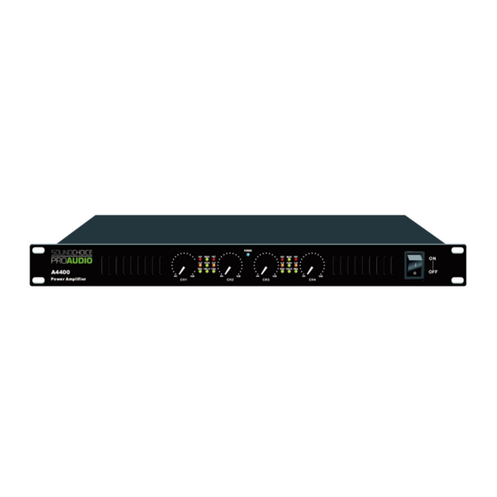
- Page 4 FRONT PANEL 1. CH1 volume knob 7. CH3 volume knob 2. CH1 protect, clip & signal indicators 8. CH3 protect, clip & signal indicators 3. Bridge, stereo & parallel indicators 9. Bridge, stereo & parallel indicators 4. CH2 protect, clip & signal indicators 10.
- Page 5 AMPLIFIER OPERATION GUIDE Setup Before operating the A series amplifiers, check the mains supply voltage and connect the IEC inlet to the mains power supply using the power lead supplied (or equivalent). Ensure that the cooling vents at front and rear are not covered or obstructed in any way with adequate space for air-flow through the unit.
- Page 6 SPECIFICATION A4100 A4200 A4300 A4400 Model Description Four Channel Power Amplifier Rated Output 4Ω 4×170W 4×350W 4×500W 4×600W Rated Output 8Ω 4×100W 4×200W 4×300W 4×400W Bridge Out 4Ω 2×330W 2×600W 2×900W 2×1000W Bridge Out 8Ω 2×160W 2×330W 2×500W 2×630W Frequency Response 20Hz~20KHz <0.3% S/N Ratio...
- Page 7 SERVICE Procedures Ensure the problem is not related to operator error, or system devices that are external to this unit. Information provided in the troubleshooting portion of this manual may help with this process. Once it is certain that the problem is related to the product contact your warranty provider as described in the warranty section of this manual.
Need help?
Do you have a question about the A4 Series and is the answer not in the manual?
Questions and answers