
Subscribe to Our Youtube Channel
Related Manuals for Tuxhorn tubra- PGS multi

Summary of Contents for Tuxhorn tubra- PGS multi
- Page 1 ® tubra - PGS multi Pumpstation für Solaranlagen Montage- und Bedienungsanleitung...
-
Page 2: Table Of Contents
Inhalt Einführung ........................3 Verwendungszweck ....................3 Sicherheitshinweise....................3 Mitgeltende Unterlagen ................... 3 Lieferung und Transport ..................3 Aufbau – Lieferumfang ....................4 Technische Daten ......................5 Allgemein ........................ 5 Abmessungen / Platzbedarf ..................6 Druckverlust ......................6 Montage ......................... 7 Wandmontage ...................... -
Page 3: Einführung
E i n f ü h r u n g Diese Anleitung beschreibt die Montage der Solarstation tubra ® -PGS multi sowie die Bedie- nung und die Wartung. Lesen Sie diese Anleitung vor Beginn der Montagearbeiten sorgfältig durch. Bei Nichtbeachtung entfallen sämtliche Garantie- und Gewährleistungsansprüche. Die Anleitung richtet sich an ausgebildete Fachhandwerker, die entsprechende Kenntnisse im Umgang mit Heizungsanlagen, Wasserleitungsinstallationen und mit Elektroinstallationen haben. -
Page 4: Aufbau - Lieferumfang
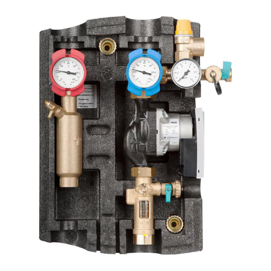
A u f b a u – L i e f e r u m f a n g Pos. Bezeichnung Pos. Bezeichnung Vorlauf-Kugelhahn mit integrierter Zeigerthermometer Schwerkraftbremse Montageplatte Rücklauf-Kugelhahn mit integrierter Formfeder Schwerkraftbremse Dämmung bestehend aus Solarsicherheitsventil 6/10 bar Vorder- und Hinterschale Kesselfüll- und Entleerungshahn Anschluss Membranausdehnungsgefäß... -
Page 5: Technische Daten
T e c h n i s c h e D a t e n Allgemein ® Bezeichnung / Typ tubra -PGS multi Max. Kollektorfläche (Flachkollektor) 26 m² Nennleistung bei ΔT 12K 13 kW Empfohlene Betriebsweise High-Flow (30 l/m²h) Max. Betriebsdruck 6/10 bar Max. -
Page 6: Abmessungen / Platzbedarf
Abmessungen / Platzbedarf Druckverlust Art.-Nr. 676.15.67.00 Stand 2021/09/09 - 6 -... -
Page 7: Montage
M o n t a g e Wandmontage Vorlauf- und Rücklaufstrang aus der Montageplatte [12] herausziehen. Befestigungspunkte der Montageplatte [12] an der Wand anzeichnen und zwei Löcher ø8 mm bohren. Dübel setzen und Montageplatte [12] mit den Schrauben und Unterlegscheiben festschrau- ben. -
Page 8: Hydraulischer Anschluss
Hydraulischer Anschluss Bezeichnung Beschreibung Solarvorlauf Solarrücklauf Speichervorlauf Speicherrücklauf Beispieldarstellung, erhebt keinen Anspruch auf Voll- ständigkeit und ersetzt keine fachmännische Planung. Achtung! Zum Eindrehen der Anschlüsse am Solarvor- lauf- und Solarrücklauf-Kugelhahn die Griffe der Kugelhähne in Stellung „geschlossen“ drehen (Griffe stehen waagerecht). Beim Festdrehen der Anschlüsse am Kugel- hahn gegenhalten [A]! Abschließend die Kugelhähne in Stellung „ge-... -
Page 9: Elektrischer Anschluss
E l e k t r i s c h e r A n s c h l u s s Allgemein Arbeiten an der elektrischen Anlage sowie das Öffnen von Elektrogehäusen darf nur in spannungsfreiem Zustand und nur von autorisiertem Fachpersonal durchgeführt werden. Bei den Anschlüssen auf richtige Klemmenbelegung und Polarität achten. -
Page 10: Funktion Der Schwerkraftbremsen
F u n k t i o n d e r S c h w e r k r a f t b r e m s e n Die Schwerkraftbremsen sind jeweils im Vorlauf-[1] und Rücklauf-Kugelhahn [2] integriert. Die Betätigung erfolgt durch Drehung der Griffe der Kugelhähne. Betriebsstellung Zur Verhinderung der Schwerkraftzirkulation dürfen die Ventilteller nicht angelüftet sein. -
Page 11: Durchflussanzeiger
D u r c h f l u s s a n z e i g e r Die Einstellung des Volumenstromes des Wärmeträgermediums erfolgt erst über die Einstellung der Drehzahlstufen der Umwälz- pumpe und dann über die Drossel [B] am Durchflussanzeiger. -
Page 12: Befüllen, Spülen Und Entleeren
B e f ü l l e n , S p ü l e n u n d E n t l e e r e n Befüllen Zum Befüllen der Solaranlage muss der Vorlauf- und Rücklaufkugelhahn [1, 2] in Stellung „Schwerkraftbremse geöffnet“... -
Page 13: Kontrollspülung
Kontrollspülung Schritt 1 Spindel [B] in Stellung „S“ drehen. Der Schlitz steht waagerecht, Abflachung nach links. Vorlaufkugelhahn [1] in Betriebsstellung, Rück- laufkugelhahn [2] in 45° Stellung. Befüllschlauch am KFE-Hahn [4a] anschließen. Entleerschlauch am KFE-Hahn [4b] anschließen. Die KFE-Hähne öffnen und die Kontrollspülung wie dargestellt durchführen. -
Page 14: Regelung (Optional)
R e g e l u n g ( o p t i o n a l ) 10.1 Bedienung Beachten Sie hierzu die Montage- und Bedienungsanleitung der verwendeten Regelung. 10.2 Einstellungen Beachten Sie hierzu die Montage- und Bedienungsanleitung der verwendeten Regelung. I n b e t r i e b n a h m e Voraussetzung für die Inbetriebnahme ist eine vollständige Installation aller hydraulischen und elektrischen Komponenten. -
Page 15: Störungen / Fehlerbehebung
S t ö r u n g e n / F e h l e r b e h e b u n g Liegt eine Fehlermeldung vor, wird diese im Display der Regelung angezeigt. Bitte beachten Sie hierzu die entsprechende Anleitung der Regelung. Störung Mögliche Ursache Behebung... -
Page 16: Wartung / Service
W a r t u n g / S e r v i c e Der Hersteller empfiehlt eine jährliche Wartung durch autorisiertes Fachpersonal durchzufüh- ren. A u ß e r b e t r i e b n a h m e 14.1 Vorübergehend Bleibt die Solarstation tubra... -
Page 17: Konformitätserklärungen
15.2 Konformitätserklärungen 15.2.1 Wilo Yonos Para Art.-Nr. 676.15.67.00 Stand 2021/09/09 - 17 -... - Page 18 15.2.2 Grundfos Art.-Nr. 676.15.67.00 Stand 2021/09/09 - 18 -...
- Page 19 Art.-Nr. 676.15.67.00 Stand 2021/09/09 - 19 -...
- Page 20 Händler Gebr. Tuxhorn GmbH & Co. KG • Senner Straße 171 • 33659 Bielefeld Tel.: +49 (0) 521 44 808-0 • Fax: +49 (0) 521 44 808-44 • www.tuxhorn.de...
- Page 21 ® tubra - PGS multi Pump station for solar systems Assembly and operating manual...
- Page 22 Content Introduction ........................3 Intended use ......................3 Safety instructions ....................3 Applicable documents ..................... 3 Delivery and transport ..................... 3 Layout – scope of delivery ....................4 Technical data ........................ 5 General description ....................5 Dimensions/required space ..................6 Pressure loss ......................
-
Page 23: Introduction
I n t r o d u c t i o n ® This manual describes the installation process for the tubra -PGS multi solar station, as well as its operating and maintenance procedures. Read this manual carefully before starting any installation work. Non-compliance will invalidate all claims under the guarantee and warranty. -
Page 24: Layout - Scope Of Delivery
L a y o u t – s c o p e o f d e l i v e r y Item Designation Item Designation Dial thermometer Supply ball valve with integrated gravity brake Wall mounting sets Shaped spring Return ball valve with integrated gravity brake Insulation consist of... -
Page 25: Technical Data
T e c h n i c a l d a t a General description ® Designation/type tubra -PGS multi Max. collector surface (flat plate collector) 26 m² Nominal output at ΔT 12K 13 kW Recommended mode of operation High-Flow (30 l/m²h) Max. -
Page 26: Dimensions/Required Space
Dimensions/required space Pressure loss Art.-Nr. 676.15.67.00 Dated 2021/09/09 - 6 -... -
Page 27: Assembly
A s s e m b l y Wall-mounted assembly Pull the feed and return line from the mount- ing plate [12]. Mark drilling points for the mounting plate [12] on the wall and drill two ø8 mm holes. Insert the wall plugs and secure the mounting plate [12] in place by using the screws and washers. -
Page 28: Hydraulic Connection
Hydraulic connection Designation Description Solar supply line Solar return line Tank supply Tank return This is a sample illustration which does not claim to be exhaustive; it does not replace specialist planning. Caution ! To close the connections of the solar flow and return ball valve, rotate the handles of the ball valves to the "closed"... -
Page 29: Electrical Connections
E l e c t r i c a l c o n n e c t i o n s General description Only authorised, specialist personnel is permitted to open electrical housings and work on the electrical system after de-energising the equipment. When creating connections, make sure the terminal assignments and polarity are correct. -
Page 30: Gravity Brake Function
G r a v i t y b r a k e f u n c t i o n The gravity brakes are integrated in the supply [1] and return ball valve [2]. They are opera- ted by turning the ball valve handles. Operating position In order to prevent circulation under the force of gravity, the valve discs should not be... -
Page 31: Flow Meter
F l o w m e t e r The flow rate of the heat transfer fluid is ad- justed initially via the speed settings on the circulation pump and then via the throttle [B] on the flow indicator. The flow indicator displays the set volume flow. -
Page 32: Filling, Flushing And Draining
F i l l i n g , f l u s h i n g a n d d r a i n i n g Filling In order to fill the solar system the supply and return ball valve [1, 2] must be set to the "gravity brake open"... -
Page 33: Controlled Flush
Controlled flush Step 1 Turn the spindle [B] to the "S" position. The slot is now horizontal, while the flat section points to the left. Set the supply ball valve [1] to the operating posi- tion; set the return ball valve [2] to a 45° setting. Connect the filling hose to the filling and drain valve [4a]. -
Page 34: Regulation (Optional)
R e g u l a t i o n ( o p t i o n a l ) 10.1 Operation Observe the installation and operating instructions of the control used. 10.2 Settings Observe the installation and operating instructions of the control used for this purpose. S t a r t - u p Complete installation of all hydraulic and electrical components is a precondition for commis- sioning. -
Page 35: Malfunctions / Troubleshooting
M a l f u n c t i o n s / t r o u b l e s h o o t i n g If an error message is present, it is shown in the display of the control. Please refer to the corresponding instructions for the control. -
Page 36: Maintenance/Service
M a i n t e n a n c e / s e r v i c e The manufacturer recommends having the system serviced annually by authorised, special- ist personnel. D e c o m m i s s i o n i n g 14.1 Temporary ®... -
Page 37: Declarations Of Conformity
15.2 Declarations of conformity 15.2.1 Wilo Yonos Para Art.-Nr. 676.15.67.00 Dated 2021/09/09 - 17 -... - Page 38 15.2.2 Grundfos Art.-Nr. 676.15.67.00 Dated 2021/09/09 - 18 -...
- Page 39 Art.-Nr. 676.15.67.00 Dated 2021/09/09 - 19 -...
- Page 40 Reseller Gebr. Tuxhorn GmbH & Co. KG • Senner Straße 171 • 33659 Bielefeld Tel.: +49 (0) 521 44 808-0 • Fax: +49 (0) 521 44 808-44 • www.tuxhorn.de...
- Page 41 ® tubra -PGS multi Stazione pompa per impianti solari Istruzioni di assemblaggio e d'uso...
- Page 42 Indice Introduzione ........................3 Scopo d'utilizzo ....................... 3 Avvertenze di sicurezza ..................3 Documentazione associata ..................3 Fornitura e trasporto ....................3 Struttura – Fornitura ....................... 4 Dati tecnici........................5 Generale ......................... 5 Dimensioni / Ingombro .................... 6 Caduta di pressione ....................6 Montaggio ........................
-
Page 43: Introduzione
I n t r o d u z i o n e ® Le presenti istruzioni descrivono il montaggio della stazione solare tubra -PGS multi, il suo impiego e la sua manutenzione. Leggere attentamente le presenti istruzioni prima di iniziare i lavori di montaggio. La mancata osservanza di dette istruzioni farà... -
Page 44: Struttura - Fornitura
S t r u t t u r a – F o r n i t u r a Pos. Denominazione Pos. Denominazione Rubinetto a sfera di mandata con Termometro a lancetta Freno di gravità Piastra di montaggio Molla sagomata Rubinetto a sfera di riflusso con freno gra- vitazionale integrato Isolamento composto da... -
Page 45: Dati Tecnici
D a t i t e c n i c i Generale ® Descrizione / Tipo tubra -PGS multi Max. superficie di collettori (collettore piatto) 26 m² Potenza nominale con ΔT 12K 13 kW Modalità di funzionamento raccomandata High-Flow (30 l/m²h) Max. -
Page 46: Dimensioni / Ingombro
Dimensioni / Ingombro Caduta di pressione Grundfos UPM 3 15-75 PWM Art.-Nr. 676.15.67.00 Ultimo aggiornamento 2021/09/09 - 6 -... - Page 47 Wilo Yonos Para 15/7.0 Perdita di pressione PGS multi, PGS-01 con flussimetro Art.-Nr. 676.15.67.00 Ultimo aggiornamento 2021/09/09 - 7 -...
-
Page 48: Montaggio
M o n t a g g i o Montaggio a parete Estrarre dalla piastra di montaggio [12 ] il condotto di mandata e di riflusso. Segnare i punti di fissaggio della piastra di montaggio [12] sulla parete e creare due fori di ø8 mm. -
Page 49: Attacco Idraulico
Attacco idraulico Denominazio- Descrizione Mandata solare Ritorno solare MANDSERB Mandata serbatoio RITSERB Ritorno serbatoio Illustrazione esemplificativa, non ha alcuna pretesa di completezza e non sostituisce la progettazione a regola d'arte. Attenzione! Per avvitare gli attacchi dei rubinetti a sfera di mandata solare e di riflusso solare girare le impugnature dei rubinetti a sfera in posizione "chiuso“... -
Page 50: Allacciamento Elettrico
A l l a c c i a m e n t o e l e t t r i c o Generale I lavori sull'impianto elettrico e l'apertura delle custodie dei componenti elettrici possono es- sere effettuati solamente a corrente elettrica scollegata e solo da personale specializzato opportunamente autorizzato. -
Page 51: Funzionamento Dei Freni Gravitazionali
F u n z i o n a m e n t o d e i f r e n i g r a v i t a z i o n a l i I freni gravitazionali sono rispettivamente integrati nel rubinetto di mandata [1] e riflusso [2]. L'azionamento avviene girando le impugnature dei rubinetti. -
Page 52: Indicatore Di Flusso
I n d i c a t o r e d i f l u s s o L'impostazione della mandata del vettore ter- mico avviene dapprima attraverso la regola- zione dei livelli del numero di giri della pompa di circolazione, poi tramite la farfalla [B] dell'indicatore di flusso. -
Page 53: Travasare, Lavare E Svuotare
T r a v a s a r e , l a v a r e e s v u o t a r e Travasare Ai fini del travaso dell'impianto solare il rubinetto a sfera di mandata e riflusso [1, 2] deve trovarsi in posizione "Freno gravitazionale aperto“... -
Page 54: Lavaggio Di Controllo
Lavaggio di controllo Passo 1 Portare l'asta [B] in posizione "S“. L'intaglio si trova in posizione orizzontale, lo spia- namento è rivolto verso sinistra. Rubinetto a sfera di mandata [1] in posizione di funzionamento, rubinetto a sfera di riflusso [2] in posizione a 45°. -
Page 55: Dispositivo Di Regolazione (Opzionale)
D i s p o s i t i v o d i r e g o l a z i o n e ( o p z i o n a l e ) 10.1 Impiego Rispettare al proposito le istruzioni di montaggio e d'uso del dispositivo di regolazione impie- gato. -
Page 56: Guasti / Risoluzione Dei Problemi
G u a s t i / r i s o l u z i o n e d e i p r o b l e m i Gli eventuali messaggi di errore vengono visualizzati sul display del dispositivo di regolazio- Rispettare al proposito le relative istruzioni del dispositivo. -
Page 57: Manutenzione / Servizio
M a n u t e n z i o n e / S e r v i z i o Il produttore consiglia di far effettuare la manutenzione ogni anno da personale specializzato opportunamente autorizzato. M e s s a f u o r i f u n z i o n e 14.1 Temporanea ®... -
Page 58: Dichiarazioni Di Conformità
15.2 Dichiarazioni di conformità 15.2.1 Wilo Yonos Para Art.-Nr. 676.15.67.00 Ultimo aggiornamento 2021/09/09 - 18 -... - Page 59 15.2.2 Grundfos Art.-Nr. 676.15.67.00 Ultimo aggiornamento 2021/09/09 - 19 -...
- Page 60 Rivenditore Gebr. Tuxhorn GmbH & Co. KG • Senner Straße 171 • 33659 Bielefeld, Germania Tel.: +49 521 44 808-0 • Fax: +49 521 44 808-44 • www.tuxhorn.de...
Need help?
Do you have a question about the tubra- PGS multi and is the answer not in the manual?
Questions and answers