Table of Contents
Advertisement
Quick Links
ILLUSTRATIONS
Round Hole
1
2
components
shock.
From House:
Power Supply
Neutral
Earth (Yellow/Green)
4
5
Follow diagram above to connect wires.
Make sure that all exposed wiring is secured inside the
NOTE: Flushmouting will not require the downrod.
terminal block.
Mounting Slots
DOWNROD INSTALLATION ONLY
Mounting Slots
Carefully lift fan from mounting plate hook, making sure not to
break any wire connections. The canopy has 2 mating slots and 2
mating holes (see illustration). Position both slots in canopy
directly under and in line with 2 mounting plate screws and lock
washers lift fan until mounting plate screws are seated in
bottom of slots in canopy. Rotate clockwise until both
After fan is installed tighten
7
mounting screws drop into slot recesses. Tighten screws
8
true-balance canopy bolts with pliers or wrench to
securely. Install third and fourth screws with lock washer
eliminate wobble during operation.
into mating holes and tighten.
NOTE: Over-tightening bolts may damage canopy.
WALL CONTROL INSTALLATION
1
2
3
Two Wires are required to operate the fan from the wall control.
10
1) "Actile" wire form lighting circuit of the fuse box, connected to
terminal A on the wall control.
2) "Fan Active" wire from the fan connects to F on the wall control.
ENVIRONMENTAL PROTECTION
Waste electrical & Electronic equipment regulations requires that any of our products showing this
marking must not be disposed of with other household or commercial waste. To prevent possible
harm to the environment or human health from uncontrolled waste disposal, please separate any
such products from other waste types and recycle it responsibly at your local facilities.
Mounting Bracket
Clamp
Pin
Slotted Hole
Cross
Set Screws
Pin
Insert downrod into downrod yoke. Make sure to align
hole in downrod with the hole in downrod yoke.
Lift canopy and install yoke cross pin through yoke
3
downrod.
Insert clamp pin into cross pin until it snaps into place.
Tighten of set screw in yoke.
Clamp Ring
Canopy Tab
4 Pole
Connector
Ball Notch
From Fan:
L - Block
Insert downrod and ball assembly into large opening in
N - Block
canopy, making sure canopy tab engages notch in
- Block
downrod ball. Place true-balance clamp ring over down-
6
rod ball and install 3 true-balance bolts through the
bottom of the canopy and into clamp ring.
(These bolts will be tightened correctly in step #9) .
ATTACHING THE BLADES
Attach blades to top of motor using screws and
9
washers shown above.
WIRING GUIDE
Ø
A
F
L
1
3
2
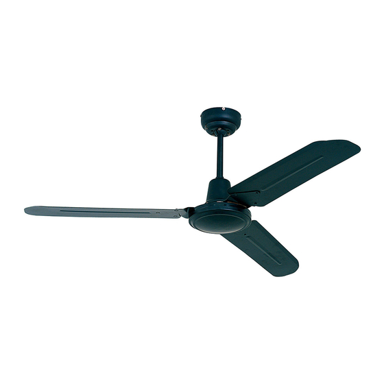
3 Blade Industrial Ceiling Fan
PRODUCT CODE
Cape Town - 9 Racecourse Road, Milnerton, 7441
Johannesburg - 10 Milkyway Avenue, Linbro Business Park, Sandton, 2065
email: admin@eurolux.co.za
Please read instructions before commencing installation and retain for
future reference.
F12B / CH / W
www.eurolux.co.za
, web:
Advertisement
Table of Contents

Subscribe to Our Youtube Channel
Related Manuals for Eurolux F12B


Summary of Contents for Eurolux F12B
- Page 1 ATTACHING THE BLADES Mounting Slots PRODUCT CODE F12B / CH / W Carefully lift fan from mounting plate hook, making sure not to break any wire connections. The canopy has 2 mating slots and 2 mating holes (see illustration). Position both slots in canopy...
- Page 2 1) Check fuses are in place in the switchboard. 2) Recheck the terminal strip connections. F12B / CH / W attachments: 3) Ensure the wall & direction switches are not stuck in a “middle” position. Should your fan be noisy:...
Need help?
Do you have a question about the F12B and is the answer not in the manual?
Questions and answers