
Subscribe to Our Youtube Channel
Related Manuals for Zero Zone CRYSTAL MERCHANDISER RVMC24

Summary of Contents for Zero Zone CRYSTAL MERCHANDISER RVMC24
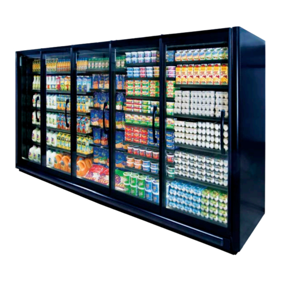
- Page 1 ZERO ZONE CRYSTAL MERCHANDISER COOLERS ® RVMC With CoolView Doors and ChillBrite lED lighting ® ® INSTALLATION & OPERATION MANUAL COMPLIANT 66-0014 REV G • Jul 2022...
-
Page 2: Table Of Contents
Table of Contents ZERO ZONE WARRANTY ..................1 INTRODUCTION ..................... 2 ƒ Important user Information ................2 ƒ Manufacturer ..................... 2 ƒ Intended use ..................... 2 ƒ Display Case Models ..................2 ƒ Case Features ....................3 ƒ Testing Standards ..................... 3 INSTALLATION &... -
Page 3: Zero Zone Warranty • 1
Zero Zone that the compressor is inoperative due to defects in factory workmanship or material under normal use and services as outlined by Zero Zone in its Installation &... -
Page 4: Introduction
The information in this manual is subject to change without notice and does not represent a commitment on the part of Zero Zone. Zero Zone does not assume any responsibility for any errors that may appear in this manual. In no event will Zero Zone be liable for technical or editorial omissions made herein, nor for direct, indirect, special, incidental, or consequential damages resulting from the use or defect of this manual. -
Page 5: Case Features
INTRODUCTION Case Features Zero Zone produces high quality refrigerated display cases using state-of-the-art components. The cases are built with the thickest insulation in the industry and a high efficiency evaporator coil. Case features include: Brushless DC electronic motors ƒ Zero Zone ChillBrite lED lighting ƒ... -
Page 6: Installation & Operation
Zero Zone cases must not be installed in the direct rays of the sun or near a source of radiant heat. Be certain that the floor under the installation is of sufficient strength to prevent sagging. Uneven surfaces will result in reduced performance. -
Page 7: Moving Cases
OPTIONAL BASES For low shipping height applications, such as 80" tall doorways, Zero Zone offers 1" bases or 1 3/4" bases. Cases with 1" bases will be shipped on a wooden pallet and are not forkliftable. The case can be removed from the pallet to slide it through ƒ... -
Page 8: Leveling
INSTALLATION & OpERATION (See Figure 3). The drain elbow will be shipped loose and Cases with 1" or 1 3/4" bases will be set on hat channel rails or into nested bases must be installed using extra thick PVC cement after the case set in place. Spacer blocks (also called filler blocks) are included in the end bases of 4-door, 5-door, and 6-door cases that use bases which are taller than 3 1/2". - Page 9 INSTALLATION & OpERATION FIGURE 7: Hat Channel Rail Orientation Base Hat Channel Rail Shim Position hat channel rails with tape up. Place shims perpendicularly under the hat channel rails. 2-door cases get 2 hat channel rails. ƒ...
- Page 10 INSTALLATION & OpERATION FIGURE 10: RVMC30 Base Locations Drawings are top views with bases shown under the case. The front of the case is toward the bottom of the page. Case length does not include end panels (2 1/2" wide each). 2RVMC30 3RVMC30 4RVMC30...
- Page 11 INSTALLATION & OpERATION FIGURE 11: RVMC24 Base Locations Drawings are top views with bases shown under the case. The front of the case is toward the bottom of the page. Case length does not include end panels (1 1/2" wide each). 2RVMC24 3RVMC24 4RVMC24...
- Page 12 INSTALLATION & OpERATION FIGURE 12: RVMC30D (Deep Case) Base Locations Drawings are top views with bases shown under the case. The front of the case is toward the bottom of the page. Case length does not include end panels (2 1/2" wide each). 2RVMC30D 3RVMC30D 4RVMC30D...
- Page 13 INSTALLATION & OpERATION FIGURE 13: RVMC24D (Deep Case) Base Locations Drawings are top views with bases shown under the case. The front of the case is toward the bottom of the page. Case length does not include end panels (1 1/2" wide each). 2RVMC24D 3RVMC24D 4RVMC24D...
- Page 14 INSTALLATION & OpERATION The case is designed with minimal gaps between adjacent doors to provide a clean appearance. To maintain even, consistent gaps and proper door operation, the case must be leveled front-to-back and side-to-side. Ensure that the case is set square to within 1/8" (See Figure 15).
-
Page 15: Lineup Assembly
Total height of shims should be less than 3/4". lineup Assembly Zero Zone display cases have been designed for continuous display so that multiple cases may be joined together to create a lineup of any ... -
Page 16: Ultra Narrow Case Anchoring
TO CENTER TO CENTER TO-WALL 14 • Installation & Operation TOLERANCES SHALL APPLY MATERIAL: REVISION INFORMATION ZERO ZONE, INC. UNLESS OTHERWISE SPECIFIED .X = ± .1 .XX = ± .02 110 NORTH OAKRIDGE DRIVE .XXX = ± .005 ANGLES, ± 1º... - Page 17 INSTALLATION & OpERATION Before joining the cases, remove all packaging material on the display case, including any spacer blocks inside the bases. Repeat caulking between each case in the lineup. FIGURE 18: Case Joint Caulking (Butyl*) DETAIL A DETAIL B Critical Area: Apply caulk along center of metal flanges...
- Page 18 INSTALLATION & OpERATION FIGURE 19: NSF Compliance Sealing (Silicone) Seal between all access holes and cut-outs THIS PROCEDURE MUST BE FOLLOWED FOR NSF COMPLIANCE. SURFACES TO BE SEALED MUST BE CLEAN, DRY, FREE OF BUTYL CAULK, AND FREE OF FROST (ABOVE 40ºF). DR-295-B Note: Cases must be properly caulked and joined before NSF sealing.
-
Page 19: Door Leveling (Door Sag/Sawtooth)
INSTALLATION & OpERATION FIGURE 20: Anchoring Ultra Narrow to Another Case 9'1 1/2" 3" GAP BETWEEN CASES LEFT SWING DOORS RELEASED SCREW CASE-TO-CASE 9" RIGHT SWING DOORS SUPPORT BRKT (18-0066) IN CEILING OF 2RVMC24UN 7" & 3RVMC24BBUN DOUBLE STICK TAPE THE CASE-TO-CASE TRIM TO THE 2RVMC24UN END CASE-TO-CASE TRIM (37-0528-XP1) -
Page 20: Bottom Mounting Plate
“R” trap are shipped loose for field installation. Condensate Removal System Zero Zone remote cases can be equipped with a condensate removal system. The system uses a drain pan with pump located behind the kickplate and a condensate evaporation pan mounted on the top of the case. -
Page 21: Kickplates
INSTALLATION & OpERATION Kickplates FIGURE 24: Kickplate Installation Each case is shipped with a front kickplate. Cases with end panels are shipped with 1 side kickplate per end panel. Cases that join together are shipped with a kickplate splice. -
Page 22: Door Gasket
INSTALLATION & OpERATION DOOR GASKET upper and lower horizontal magnetized gaskets run the length of each case. The gaskets mate up to steel plates installed at the top and bottom of each door. A vertical gasket runs along the hinge-side of each door. The gasket seals against the handle-side of each adjacent door. At the end of each case, another gasket is placed on the handle-side of the door and is used to seal against the side of the case (instead of an adjacent door). -
Page 23: Rear Load Cases
INSTALLATION & OpERATION Rear load Cases Rear load cases are shipped with the rear sliding doors removed and shipped loose with the case. To maintain proper temperature, the Rear load case must be positioned in the opening of a walk-in cooler. Before attaching the cases to the walk-in, measure the diagonal opening of the Rear load case to ensure a square case installation. -
Page 24: Refrigeration
Refrigerant Piping Correct refrigeration line sizing and industry standard installation practices are essential for proper system operation. Zero Zone offers many refrigerant choices. We recommend using the Sporlan Virtual Engineer Toolbox to calculate sizing for liquid, suction, and discharge lines: https://solutions.parker.com/sporlanvirtualengineer. -
Page 25: Operation Set Points
Adjust evaporator pressure as needed to maintain discharge air temperature. To receive the full benefit of high-glide refrigerant properties, the superheat may need to be lowered to 4-6°F. Contact Zero Zone with questions. Defrost Crystal Merchandiser coolers can be set up with either off-cycle defrost or electric defrost. -
Page 26: Electrical
ELECTRICAL ELECTRICAL General CAUTION! DISCONNECT POWER TO THE CASE BEFORE SERVICING ElECTRICAl COMPONENTS TO AVOID PERSONAl INJuRY AND DAMAGE TO THE uNIT. Cases may have 2 or 3 electrical circuits. Standard cases have 2 electrical circuits: the fan FIGURE 35: Light Switch circuit and the lighting circuit. -
Page 27: Maintenance
Cleaning Although each Zero Zone display case is thoroughly cleaned before shipping, the cases should be thoroughly cleaned again before start-up and routinely thereafter to maintain a clean appearance. With just a few minutes of cleaning each week, the case will remain in top condition. - Page 28 Technical Resources page at: WWW.ZERO-ZONE.COM or contact the Zero Zone Service Department at: 800-247-4496 All specifications subject to change without notice. ZERO ZONE, INC. • 800-247-4496 • ZERO-ZONE.COM © 2022 Zero Zone, Inc. All Rights Reserved. • Jul 2022 66-0014 REV G...
Need help?
Do you have a question about the CRYSTAL MERCHANDISER RVMC24 and is the answer not in the manual?
Questions and answers