Grizzly G0580 Owner's Manual
14" bandsaw
Hide thumbs
Also See for G0580:
- Parts breakdown (5 pages) ,
- Instruction manual (60 pages) ,
- Owner's manual (64 pages)
Table of Contents
Advertisement
Quick Links
MODEL G0580
14" BANDSAW
OWNER'S MANUAL
(For models manufactured since 11/06)
COPYRIGHT © AUGUST, 2004 BY GRIZZLY INDUSTRIAL, INC. REVISED MARCH, 2015 (BL)
WARNING: NO PORTION OF THIS MANUAL MAY BE REPRODUCED IN ANY SHAPE
OR FORM WITHOUT THE WRITTEN APPROVAL OF GRIZZLY INDUSTRIAL, INC.
#CA6492 PRINTED IN TAIWAN
Advertisement
Table of Contents

Related Manuals for Grizzly G0580


Summary of Contents for Grizzly G0580
- Page 1 OWNER'S MANUAL (For models manufactured since 11/06) COPYRIGHT © AUGUST, 2004 BY GRIZZLY INDUSTRIAL, INC. REVISED MARCH, 2015 (BL) WARNING: NO PORTION OF THIS MANUAL MAY BE REPRODUCED IN ANY SHAPE OR FORM WITHOUT THE WRITTEN APPROVAL OF GRIZZLY INDUSTRIAL, INC.
- Page 2 This manual provides critical safety instructions on the proper setup, operation, maintenance, and service of this machine/tool. Save this document, refer to it often, and use it to instruct other operators. Failure to read, understand and follow the instructions in this manual may result in fire or serious personal injury—including amputation, electrocution, or death.
-
Page 3: Table Of Contents
Table of Contents INTRODUCTION ..........2 SECTION 5: ACCESSORIES ......41 Manual Accuracy ........... 2 SECTION 6: MAINTENANCE ......43 Contact Info............ 2 Schedule ............43 Identification ........... 3 Cleaning & Protecting ........43 Machine Data Sheet ........4 Lubrication ........... 43 SECTION 1: SAFETY ........ -
Page 4: Introduction
Do not remove jammed cutoff pieces until blade has stopped. c) Maintain proper adjustment of blade tension, blade guides, thrust Manufacture Date bearings. d) Adjust upper guide just clear workpiece. Serial Number e) Hold workpiece firmly against table. Model G0580 (Mfd. Since 11/06) -
Page 5: Identification
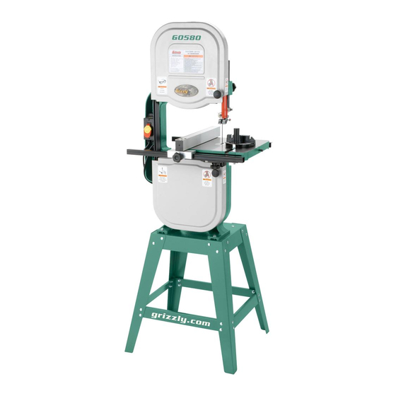
G. Miter Gauge Assembly R. Rear Table Lock Knob H. Lower Wheel Cover Fence Lock Knob Front Table Lock Knob K. Stand Assembly To reduce your risk of serious injury, read this entire manual BEFORE using machine. Model G0580 (Mfd. Since 11/06) -
Page 6: Machine Data Sheet
MACHINE DATA SHEET Customer Service #: (570) 546-9663 · To Order Call: (800) 523-4777 · Fax #: (800) 438-5901 MODEL G0580 14" BANDSAW 3/4 HP Product Dimensions: Weight................................154 lbs. Width (side-to-side) x Depth (front-to-back) x Height..............26 x 27 x 67-1/4 in. - Page 7 The information contained herein is deemed accurate as of 3/30/2015 and represents our most recent product specifications. Model G0580 PAGE 2 OF 2 Due to our ongoing improvement efforts, this information may not accurately describe items previously purchased. Model G0580 (Mfd. Since 11/06)
-
Page 8: Section 1: Safety
Everyday ery. Never operate under the influence of drugs or eyeglasses are NOT approved safety glasses. alcohol, when tired, or when distracted. Model G0580 (Mfd. Since 11/06) - Page 9 Contact our debris. Make sure they are properly installed, Technical Support at (570) 546-9663. undamaged, and working correctly. Model G0580 (Mfd. Since 11/06)
-
Page 10: Additional Safety For Bandsaws
Failure to do so could result in risk of operator injury. If normal safety pre- serious personal injury, damage to equip- cautions are overlooked or ignored, seri- ment, or poor work results. ous personal injury may occur. Model G0580 (Mfd. Since 11/06) -
Page 11: Section 2: Power Supply
Nominal Voltage ........230V meets the specified circuit requirements. Cycle ............60 Hz Phase ........... Single-Phase Power Supply Circuit ......15 Amps Plug/Receptacle ......NEMA 6-15 Model G0580 (Mfd. Since 11/06) - Page 12 The plug must only be inserted into a matching receptacle (see following figure) that is properly installed and grounded in accordance with all local codes and ordinances. -10- Model G0580 (Mfd. Since 11/06)
- Page 13 Plug 6-15 ............ 1 Figure 5. Saw motor rewired to 230V. Rewired for 220V To convert the Model G0580 to 230V: Close and secure the motor junction box. DISCONNECT SAW FROM POWER! Install a 6-15 plug on the power cord, accord- Neutral ing to the plug manufacturer's instructions.
-
Page 14: Section 3: Setup
Hex Wrench 5mm ........1 • Phillips Screwdriver ........1 • Machinist's Square ........1 • Ruler ............1 • Straightedge ..........1 • Leather Gloves (pair) ........1 • Feeler Gauge 0.016" ........1 -12- Model G0580 (Mfd. Since 11/06) -
Page 15: Hardware Recognition Chart
Hardware Recognition Chart -13- Model G0580 (Mfd. Since 11/06) -
Page 16: Inventory
—Flat Washers 8mm ......... 8 lost in packaging materials while unpack- —Hex Nuts M8-1.25 ........5 ing or they are pre-installed at the factory. —Hex Bolts M8-1.25 x 30 ......2 —Hex Bolts M8-1.25 x 80 ......1 -14- Model G0580 (Mfd. Since 11/06) -
Page 17: Cleanup
Repeat Steps 2–3 as necessary until clean, Figure 8. T23692 Orange Power Degreaser. then coat all unpainted surfaces with a quality metal protectant to prevent rust. -15- Model G0580 (Mfd. Since 11/06) -
Page 18: Site Considerations
Only install in an Shadows, glare, or strobe effects that may distract access restricted location. or impede the operator must be eliminated. 26" Figure 9. Minimum working clearances. -16- Model G0580 (Mfd. Since 11/06) -
Page 19: Assembling Stand
Support Braces ..........2 Wrenches or Sockets 13mm ......2 Tools Needed: Wrench or Socket 13mm ........1 The Model G0580 is a To assemble the stand: heavy machine (154 lbs.). DO NOT over-exert your- Place the base plate upside down on a flat... -
Page 20: Motor & Switch
Place the V-belt on the pulley, move the motor to the left with moderate pressure, and tighten the cap screws Push the belt with moderate pressure. If the ", repeat Step 3. belt deflects more than -18- Model G0580 (Mfd. Since 11/06) -
Page 21: Installing Blade Guides
M6-1 x 20 hex bolts and 6mm flat washers, as shown in Figure 15. Upper Blade Lower Guide Guard Assembly Lower Guard Figure 17. Installing upper blade guard. Figure 15. Installing lower blade guide assembly. -19- Model G0580 (Mfd. Since 11/06) -
Page 22: Table
(see Figure 22). Figure 19. Hex Bolts and Lock Washers Trunnions Knob Hex Bolt Figure 22. Securing trunnion to support bracket. Figure 19. Trunnion support bracket installed. -20- Model G0580 (Mfd. Since 11/06) -
Page 23: Installing Fence
Attach the front angled rail to the front of the table with two M6-1 x 20 hex bolts, flat wash- ers, and lock washers, as shown in Figure Front Rail Rear Rail Square Rail Figure 23. Installing front rail system. -21- Model G0580 (Mfd. Since 11/06) -
Page 24: Dust Collection
Figure 25. Example of attached dust hose. Tug the hose to make sure it does not come Note: See Calibrating Table Tilt Scale on off. Page 28. Note: A tight fit is necessary for proper per- formance. -22- Model G0580 (Mfd. Since 11/06) -
Page 25: Blade Center Tracking
When the blade consistently rides in the Knob Tension center of the wheel after several rotations, Scale tighten the tracking control lock nut and close the upper wheel cover. Figure 27. Blade tension and center tracking controls. -23- Model G0580 (Mfd. Since 11/06) -
Page 26: Power Connection
— Investigate and correct strange or unusual noises or vibrations before operating the machine further. Always disconnect the machine from power when investigating or correcting potential problems. Figure 30. Disconnecting power. -24- Model G0580 (Mfd. Since 11/06) -
Page 27: Tensioning Blade
After blade tension and tracking are set cor- rectly, properly adjust the upper and lower support bearings and guide-block assem- blies into position before cutting opera- tions. -25- Model G0580 (Mfd. Since 11/06) -
Page 28: Adjusting Support Bearings
Figure 34. Bolt Assembly Lock Bolt 0.016'' Support Bearing Side View Figure 32. Support bearing controls. Loosen the assembly lock bolt. Figure 34. Blade should be aligned approxi- mately 0.016" away from the bearing edge. -26- Model G0580 (Mfd. Since 11/06) -
Page 29: Adjusting Blade Guides
Guide blade support bearings and guide-blocks Blocks must be properly adjusted before cutting operations. Thumbscrews Figure 36. Blade guide controls. Loosen the thumbscrew on the adjustment rod. -27- Model G0580 (Mfd. Since 11/06) -
Page 30: Calibrating Table Tilt Scale
Tighten the screw on the pointer so that the pointer is locked in place. Tighten the thumbscrews. Whenever changing a blade or adjusting tension and tracking, the upper and lower blade support bearings and guide-blocks must be properly adjusted before cutting operations. -28- Model G0580 (Mfd. Since 11/06) -
Page 31: Aligning Table
Note: Refer to the Blade Lead instructions Note: Refer to the Blade Lead instructions on Page 52 for more table alignment adjust- on Page 52 for more fence alignment adjust- ments. ments. -29- Model G0580 (Mfd. Since 11/06) -
Page 32: Miter Gauge
Use a machinist's square with one edge against the face of the miter gauge and the other against the blade face, as shown in Figure 40. Figure 40. Squaring miter gauge to blade. -30- Model G0580 (Mfd. Since 11/06) -
Page 33: Section 4: Operations
OMMEND that you read books, review industry trade magazines, or get formal training before beginning any projects. Regardless of the content in this section, Grizzly Industrial will not be held liable for accidents caused by lack of training. -31- Model G0580 (Mfd. Since 11/06) -
Page 34: Disabling Switch
On the contrary, a workpiece supported on the bowed side will rock during a cut and could cause kickback or severe injury. -32- Model G0580 (Mfd. Since 11/06) -
Page 35: Guide Post
Loosen the guide post lock knob shown in Figure 42. Raise/lower the guide post to within 1" from the top of the workpiece to the bottom of the blade guide assembly. Lock the guide post in place with the lock knob. -33- Model G0580 (Mfd. Since 11/06) -
Page 36: Blade Information
These blades are excellent for the tough demands of resawing and rip- ping thick material. Cutting Radius Figure 44. Recommended cutting radius per blade width. -34- Model G0580 (Mfd. Since 11/06) - Page 37 Leaving blade tensioned when not in use. are excellent for cleaning dirty blades. • Using the wrong TPI for the workpiece thick- ness. (The general rule of thumb is three teeth in the workpiece at all times.) -35- Model G0580 (Mfd. Since 11/06)
-
Page 38: Blade Change
Rotate the blade 90˚ and slide through the the support bearings. slot in the table. Close the wheel covers. Replace the table insert and table pin, being sure not to use excessive force when insert- ing the table pin. -36- Model G0580 (Mfd. Since 11/06) -
Page 39: Basic Cutting Tips
If you slip, your hands or fingers may go into the blade. ALWAYS use a push stick when ripping narrow pieces. Failure to follow these warnings may result in serious personal injury! -37- Model G0580 (Mfd. Since 11/06) -
Page 40: Crosscutting
When resawing thin pieces, a wandering blade (blade lead) can tear through the side of the workpiece, exposing your hands to the blade teeth. Always use push blocks when resawing and keep your hands clear of the blade. -38- Model G0580 (Mfd. Since 11/06) -
Page 41: Cutting Curves
⁄ " ........⁄ " ⁄ " ........⁄ " ⁄ '' ........⁄ ⁄ '' ........1 ⁄ ⁄ '' ........2 ⁄ ⁄ '' ........3 ⁄ ⁄ '' ........5 ⁄ -39- Model G0580 (Mfd. Since 11/06) -
Page 42: Stacked Cuts
On the face of the top piece, lay out the Figure 50. Example of a stacked cut setup. shape you intend to cut. -40- Model G0580 (Mfd. Since 11/06) -
Page 43: Section 5: Accessories
ACCESSORIES SECTION 5: ACCESSORIES Bandsaw Blades Grizzly bandsaw blades are made from top quality saw steel manufactured to precise tolerances with Installing unapproved accessories may guaranteed welds for blades that last longer and cause machine to malfunction, resulting in produce smoother cuts. - Page 44 These super heavy-duty roller stands feature con- venient hand knobs for fast height adjustment. D2272 D2274 Figure 54. T10117 Big Mouth Dust Hood. D2273 Figure 56. Shop Fox Roller Stands. ® www.grizzly.com 1-800-523-4777 order online at or call -42- Model G0580 (Mfd. Since 11/06)
-
Page 45: Section 6: Maintenance
Keep the table rust-free with regular applications of products like G96 Gun Treatment, SLIPIT , or ® ® Daily Boeshield T-9 (contact Grizzly to purchase these ® • Check/correct loose mounting bolts. products). • Check/correct damaged or worn saw blade. •... -
Page 46: Redressing Rubber Tires
Re-install the blade, then make sure the blade tracking and tension are correct. -44- Model G0580 (Mfd. Since 11/06) -
Page 47: Section 7: Service
7. Cast iron motor mount loose/broken. 7. Tighten/replace. 8. Centrifugal switch is at fault. 8. Adjust/replace centrifugal switch.. 9. Test by rotating shaft; rotational grinding/loose 9. Motor or spindle bearings are at fault. shaft requires bearing replacement. -45- Model G0580 (Mfd. Since 11/06) - Page 48 (Page 49). each other. consistently, 2. Rubber tires on wheels are worn out. 2. Redress the rubber tires on the wheels (Page correctly, or 44); replace the rubber tires on the wheels. at all. -46- Model G0580 (Mfd. Since 11/06)
-
Page 49: V-Belt Tension
⁄ " deflection in the V-belt between the Approximately ⁄ " pulley when moderate pressure is applied. Re-tighten both cap screws and close the wheel cover. Deflection Pulley Figure 57. Checking the V-belt tension. -47- Model G0580 (Mfd. Since 11/06) -
Page 50: Replacing V-Belt
Roll the V-belt off the pulleys. Tip: For fine adjustments, use electrical washers on the bolts that secure the table. -48- Model G0580 (Mfd. Since 11/06) -
Page 51: Wheel Alignment
Make sure the straightedge fully extends across the rims of both wheels, as shown in the figure below. Figure 62. Wheel alignment illustration. Figure 61. Checking if the wheels are coplanar. -49- Model G0580 (Mfd. Since 11/06) - Page 52 Adjust the upper wheel tracking so that it is the wheels parallel, repeat this procedure. parallel with the bottom wheel. When you are satisfied with the adjustment, re-install the blade and close the wheel cov- ers. -50- Model G0580 (Mfd. Since 11/06)
- Page 53 (viewed with the upper wheel removed). cedure until the upper wheel is coplanar with the lower wheel. Rear Adjustment Set Screw Figure 65. Rear lateral adjustment set screw. -51- Model G0580 (Mfd. Since 11/06)
-
Page 54: Blade Lead
Shift the table to compensate for the blade lead, re-tighten the hex bolts, then re-connect the bandsaw to power. Repeat Steps 1–5 until there is no longer any blade lead. -52- Model G0580 (Mfd. Since 11/06) -
Page 55: Section 8: Wiring
Technical Support at (570) 546-9663. The photos and diagrams included in this section are best viewed in color. You can view these pages in color at www.grizzly.com. -53- Model G0580 (Mfd. Since 11/06) -
Page 56: Wiring Diagram
Run Capacitor 200M125V 25M 250V for 230V Ground Rewired for 230V Neutral 115 VAC 230 VAC 5-15 Plug 6-15 Plug (Pre-wired) (As Recommended) Ground Ground Rewired for 230V READ ELECTRICAL SAFETY -54- Model G0580 (Mfd. Since 11/06) ON PAGE 53! -
Page 57: Section 9: Parts
SECTION 9: PARTS Main -55- Model G0580 (Mfd. Since 11/06) - Page 58 TABLE P0580038 COIL SPRING 3.8 X 13.5 X 81 P0580098 T24385 TABLE INSERT P0580039 SQUARE NUT M10-1.5 P0580099 ROLL PIN 3 X 8 P0580040 UPPER WHEEL P0580100 TABLE PIN P0580041 WHEEL TIRE P0580101 TRUNNION -56- Model G0580 (Mfd. Since 11/06)
-
Page 59: Stand
POINTER Stand REF PART # DESCRIPTION REF PART # DESCRIPTION P0580127 BASE PLATE P0580131 LONG BRACE P0580128 BODY SUPPORT PLATE P0580132 FLANGE NUT M8-1.25 P0580129 P0580133 CARRIAGE BOLT M8-1.25 X 16 P0580130 SHORT BRACE -57- Model G0580 (Mfd. Since 11/06) -
Page 60: Fence
If any label comes off or becomes unreadable, the owner of this machine MUST replace it in the original location before resuming operations. For replacements, contact (800) 523-4777 or www.grizzly.com. -58- Model G0580 (Mfd. Since 11/06) - Page 61 Would you recommend Grizzly Industrial to a friend? _____ Yes _____No Would you allow us to use your name as a reference for Grizzly customers in your area? Note: We never use names more than 3 times. _____ Yes _____No 10.
- Page 62 FOLD ALONG DOTTED LINE Place Stamp Here GRIZZLY INDUSTRIAL, INC. P.O. BOX 2069 BELLINGHAM, WA 98227-2069 FOLD ALONG DOTTED LINE Send a Grizzly Catalog to a friend: Name_______________________________ Street_______________________________ City______________State______Zip______ TAPE ALONG EDGES--PLEASE DO NOT STAPLE...
-
Page 63: Warranty & Returns
WARRANTY & RETURNS Grizzly Industrial, Inc. warrants every product it sells for a period of 1 year to the original purchaser from the date of purchase. This warranty does not apply to defects due directly or indirectly to misuse, abuse, negligence, accidents, repairs or alterations or lack of maintenance.
Need help?
Do you have a question about the G0580 and is the answer not in the manual?
Questions and answers