Table of Contents
Advertisement
Quick Links
AD0504046AE
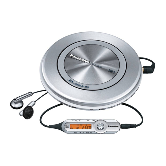
Portable CD Player
SL-CT520GK / SL-CT520GT
Colours
(A)...........Blue Type
(P)...........Pink Type [SL-CT520GK only]
(S)...........Silver Type
(Y)...........Yellow Type [SL-CT520GK only]
Please use this manual together with the service manual for Model
No. SL-CT520EB/EG/EE/SG, Order No. AD0502004C0.
2005 Matsushita Electric Industrial Co., Ltd. All rights reserved.
Unauthorized copying and distribution is a violation of law.
1
PDF created with pdfFactory Pro trial version
www.pdffactory.com
Advertisement
Table of Contents

Related Manuals for Panasonic SL-CT520EB


Summary of Contents for Panasonic SL-CT520EB
- Page 1 (S)...Silver Type (Y)...Yellow Type [SL-CT520GK only] Please use this manual together with the service manual for Model No. SL-CT520EB/EG/EE/SG, Order No. AD0502004C0. 2005 Matsushita Electric Industrial Co., Ltd. All rights reserved. Unauthorized copying and distribution is a violation of law.
- Page 2 1. Note - This simplified service manual is provided to indicate the differences between the original model No. SL-CT520SG-S and the subsequent model No. SL-CT520GK-A/P/S-Y, SL-CT520GT-A/S. 2. Replacement Parts List Note: - Important safety notice: Components identified by mark have special characteristics important for safety.
- Page 3 - All parts are supplied by SPC. Ref.No. Change of Parts No. Part Name & Description Remarks SL-CT520SG-S SL-CT520GK CABINET PARTS RGN2805-H NAME PLATE RGN2810-H1 ACCESSORIES L0BAB0000190 STEREO EARPHONES L0BAB0000183 N2QCBD000048 N2QCBD000049 WIRED REMOTE CONROL RFEA444Z-S AC ADAPTOR RFEA473T-1S RQT7819-Z OPERATING INSTRUCTIONS ------ DELETE...
- Page 4 AD0502004C0 Portable CD Player SL-CT520EB SL-CT520EG SL-CT520EE SL-CT520SG Colours (A)...Blue Type (P)...Pink Type [SL-CT520SG only] (S)...Silver Type (Y)...Yellow Type [SL-CT520SG only] © 2005 Matsushita Electric Industrial Co., Ltd. All rights reserved. Unauthorized copying distribution is a violation of law.
-
Page 5: Table Of Contents
SL-CT520EB / SL-CT520EG / SL-CT520EE / SL-CT520SG CONTENTS Page Page 1 Accessories 8 Automatic Adjustment Results Display Function (Self-Check 2 Location of Controls Function) 3 Precaution of Laser Diode 8.1. How to display automatic adjustment results 4 Handling Precautions for Traverse Deck 8.2. -
Page 6: Accessories
SL-CT520EB / SL-CT520EG / SL-CT520EE / SL-CT520SG 1 Accessories · AC adaptor for SL-CT520EB · Wired remote control for SL-CT520SG (RFEA435B-S)..........1 pc. (N2QCBD000048).........1 pc. · AC adaptor for SL-CT520EE/EG · External battery case (RFEA431E-S)..........1 pc. (RFA2666-H)..........1 pc. · AC adaptor for SL-CT520SG ·... -
Page 7: Precaution Of Laser Diode
SL-CT520EB / SL-CT520EG / SL-CT520EE / SL-CT520SG 3 Precaution of Laser Diode... -
Page 8: Handling Precautions For Traverse Deck
SL-CT520EB / SL-CT520EG / SL-CT520EE / SL-CT520SG 4 Handling Precautions for Traverse Deck The laser diode in the traverse deck (optical pick-up) may break 4.2. Caution when replacing down due to potential difference caused by static electricity of traverse deck clothes or human body. -
Page 9: Operation Checks And Component Replacement Procedures
SL-CT520EB / SL-CT520EG / SL-CT520EE / SL-CT520SG 5 Operation Checks and Component Replacement Procedures · This section describes procedures for checking the operation of the major printed circuit boards and replacing the main components. · For reassembly after operation checks or replacement, reverse the respective procedures. -
Page 10: Replacement For The Cd Lid Unit, Open Spring 1, Open Spring 2 And Retainer Plate
SL-CT520EB / SL-CT520EG / SL-CT520EE / SL-CT520SG 5.1.2. Checking for the P.C.B. (B side) · Follow the (Step 1) - (Step 5) of item 5.1.1. 5.2. Replacement for the CD lid unit, open spring 1, open spring 2 and retainer plate ·... -
Page 11: Replacement For The Traverse Motor
SL-CT520EB / SL-CT520EG / SL-CT520EE / SL-CT520SG 5.3. Replacement for the traverse motor · Follow the (Step 1) - (Step 4) of item 5.1.1. -
Page 12: Replacement For The Optical Pick-Up
SL-CT520EB / SL-CT520EG / SL-CT520EE / SL-CT520SG 5.4. Replacement for the optical pick-up · Follow the (Step 1) - (Step 4) of item 5.1.1. · Follow the (Step 1) - (Step 2) of item 5.3. -
Page 13: Replacement For The Rest Switch
SL-CT520EB / SL-CT520EG / SL-CT520EE / SL-CT520SG 5.5. Replacement for the rest switch · Follow the (Step 1) - (Step 4) of item 5.1.1. · Follow the (Step 1) , (Step 2) of item 5.4. -
Page 14: Display Of Self-Diagnostic Function
SL-CT520EB / SL-CT520EG / SL-CT520EE / SL-CT520SG 6 Display of Self-Diagnostic Function This unit (SL-CT520) has self-diagnostic function. It may display below-mentioned on the remote control display. · The substance of self-diagnostic display. Remote control display (Press PLAY and STOP button. After 15 seconds, it is displayed for 2 seconds.) -
Page 15: Checking The Operation Problems On The Traverse Deck (Optical Pick-Up)
SL-CT520EB / SL-CT520EG / SL-CT520EE / SL-CT520SG 7 Checking the Operation Problems on the Traverse Deck (Optical Pick-up) Make sure to follow the procedures below to check the replacing it. operation problems of the traverse deck (optical pick-up) before Replace the traverse deck only after the problem is identified. -
Page 16: Automatic Adjustment Results Display Function (Self-Check Function)
SL-CT520EB / SL-CT520EG / SL-CT520EE / SL-CT520SG 8 Automatic Adjustment Results Display Function (Self-Check Function) On the unit (SL-CT520), each automatic adjustment result are circuit is incorrect. displayed on the remote control display. This function is The followings are the contents of the automatic adjustment convenient to check or identify which automatic adjustment result displays (Self-Check Function). -
Page 17: Type Illustration Of Ics, Transistors And Diodes
SL-CT520EB / SL-CT520EG / SL-CT520EE / SL-CT520SG 9 Type Illustration of ICs, Transistors and Diodes B1ABMD000004 B1GFGCAA0001 MN6627962JB 128PIN C3EBCG000096 8PIN C0DBFFB00005 48PIN C3ABMG000207 50PIN C2BBGF000595 80PIN No.1 No.1 UN521LTX B1CFHA000002 MA8056MTX B3AAB0000037 2SB1182TLPQR 2SB709ATX MA8120MTX UN5114TX B1GBCFJG0004 UN521MTX Cathode... -
Page 18: Schematic Diagram
SL-CT520EB / SL-CT520EG / SL-CT520EE / SL-CT520SG 11 Schematic Diagram :POSITIVE VOLTAGE LINE :PLAYBACK SIGNAL LINE OPTICAL PICK-UP R809 R808 R811 C D E F G H I 6.8K 8.2K IC302 TRAVERSE SPINDLE S202 O P Q C3EBCG000096 MOTOR MOTOR... - Page 19 SL-CT520EB / SL-CT520EG / SL-CT520EE / SL-CT520SG :POSITIVE VOLTAGE LINE :PLAYBACK SIGNAL LINE L M N O P Q A B R517 R523 (1.4V) 1.8V ADPV 1.2V VREF TEIN C518 ATOFS 560P (1.2V) 0.9V FEIN SDRCK 3.2V AFOFS UDQM C534 (2.3V) 0V...
- Page 20 SL-CT520EB / SL-CT520EG / SL-CT520EE / SL-CT520SG :POSITIVE VOLTAGE LINE :PLAYBACK SIGNAL LINE 4.1V JK12 EXT BATT B1GBCFJG0004 DC IN DET. (AC ADAPTOR) ICP11 ERBSE1R00U CN12 2R03/LR03(UM-4) 2SB1182TLPQR BATTERIES REGULATOR (2.9V) 3.5V 3.7V 4.1V 36 35 34 33 32 31 30 29 28 27 26 25 220K 0V (0.2V)
- Page 21 SL-CT520EB / SL-CT520EG / SL-CT520EE / SL-CT520SG...
-
Page 22: Printed Circuit Board And Wiring Connection Diagram
SL-CT520EB / SL-CT520EG / SL-CT520EE / SL-CT520SG 12 Printed Circuit Board and Wiring Connection Diagram Note: This printed circuit board diagram may be modified at any time with the development of new technology. (SIDE: A) (SIDE: B) S801 (CHG) S802... - Page 23 SL-CT520EB / SL-CT520EG / SL-CT520EE / SL-CT520SG...
-
Page 24: Block Diagram
SL-CT520EB / SL-CT520EG / SL-CT520EE / SL-CT520SG 13 Block Diagram MN6627962JB OPTICAL PICK-UP IC501 SERVO AMP / SERVO PROCESSOR / SEMICONDUCTOR LASER DIGITAL SIGNAL PROCESSOR DIGITAL FILTER & D/A CONVERTER Q201 X501 LASER OPEN (16.9344MHz) POWER DRIVE 88 105 MICRO... - Page 25 SL-CT520EB / SL-CT520EG / SL-CT520EE / SL-CT520SG HEADPHONE HPOUTR HPOUTL DC IN 4.5V Q704 DC IN MUTING DET. ICP12 Q901,902,905 REGULATOR BATT MUTING C3EBCG000096 CONT. IC302 EE PROM Q903 ICP11 BUZZER RESET RESET CONT. Q301 RESET 2R03/LR03(UM-4) Q502 BATTERIES 2,3,5,6,8,...
-
Page 26: Terminal Function Of Ics
SL-CT520EB / SL-CT520EG / SL-CT520EE / SL-CT520SG 14 Terminal Function of ICs 14.1. IC301(C2BBGF000595): Terminal Function Name System Control Remote control communication signal output Terminal Function POWER Power ON signal output Name AVSS NRST Not used, open VREF Reference voltage input... - Page 27 SL-CT520EB / SL-CT520EG / SL-CT520EE / SL-CT520SG Terminal Function Terminal Function Name Name FEOUT Focus error signal amp output BLKCK Sub code block clock signal output Focus error signal amp inverting input SMCK System clock signal output Tracking error signal amp inverting input...
-
Page 28: Supply Of Rechargeable Battery As Replacement Parts
SL-CT520EB / SL-CT520EG / SL-CT520EE / SL-CT520SG 15 Supply of Rechargeable Battery as Replacement Parts Battery without Carrying Case. Please take note of the following points relating to Carrying Case to be used for protection of Rechargeable Battery from · Replacement parts will be supplied for Carrying Case shorting. -
Page 29: Replacement Parts List
SL-CT520EB / SL-CT520EG / SL-CT520EE / SL-CT520SG 17 Replacement Parts List Notes: Ref. No. Part No. Part Name & Remarks Description · Important safety notice: RGN2826-H NAME PLATE (EES)(EEA) Components identified by mark have special RGN2805-H NAME PLATE characteristics important for safety. - Page 30 SL-CT520EB / SL-CT520EG / SL-CT520EE / SL-CT520SG Ref. No. Part No. Part Name & Remarks Ref. No. Part No. Part Name & Remarks Description Description ECJ1VF1C104Z 16V 0.1U JK11 RJJ43K09-C JK,DC IN K2EB2B000006 ECEA1AKS221 10V 220U JK12 K2FB2B000002 JK,EXT BATT.
- Page 31 SL-CT520EB / SL-CT520EG / SL-CT520EE / SL-CT520SG Ref. No. Part No. Part Name & Remarks Description R323 ERJ3GEYJ104 1/10W 100K R324 ERJ3GEY0R00 1/10W 0 R325 ERJ3GEYJ333 1/10W 33K R327 ERJ3GEYJ104 1/10W 100K R328 ERJ3GEYJ104 1/10W 100K R329 ERJ3GEYJ104 1/10W 100K...
-
Page 32: Cabinet Parts Location
SL-CT520EB / SL-CT520EG / SL-CT520EE / SL-CT520SG 18 Cabinet Parts Location... -
Page 33: Traverse Unit Parts Location
SL-CT520EB / SL-CT520EG / SL-CT520EE / SL-CT520SG 19 Traverse Unit Parts Location... -
Page 34: Packaging
SL-CT520EB / SL-CT520EG / SL-CT520EE / SL-CT520SG 20 Packaging F0502KH...
Need help?
Do you have a question about the SL-CT520EB and is the answer not in the manual?
Questions and answers