Table of Contents
Advertisement
Quick Links
Advertisement
Table of Contents

Related Manuals for Data Connect DCE 5201V-BM

Summary of Contents for Data Connect DCE 5201V-BM
- Page 1 VDSL2 Converter DCE 5201V-BM / 5204V-BM User’s Manual...
- Page 3 Do not dispose of WEEE as unsorted municipal waste and have to collect such WEEE separately. Revision VDSL2 Converter User’s Manual For Models: DCE 5201V-BM / 5204V-BM Rev 1.0 (October, 2009) Part No.: 5201-BM & 5204-BM...
-
Page 4: Table Of Contents
1.3 Key Features .............. 9 1.4 Specifications ............10 2. Hardware Description ............12 2.1 Front Panel ............... 12 2.1.1 LED indicators for DCE 5201V-BM.....13 2.1.2 LED indicators for DCE 5204V-BM....14 2.2 The Rear Panel ............16 2.2.1 MODE DIP Switch ..........16 2.2.2 DC power jack .......... -
Page 5: Introduction
1. Introduction 1.1 Checklist Check the contents of your package for following parts: DCE 5201V-BM or DCE 5204V-BM Splitter (5201V-BM only) Power Adapter RJ-11 Telephone line User’s Manual If any of these pieces are missing or damaged, please contact your dealer immediately, if possible, retain the carton including the original packing material, and use them against to repack the product in case there is a need to return it to us for repair. - Page 6 This capability is ideal for use as an Ethernet extender for your existing Ethernet network. Data Connect's VDSL2 Converter solution provides a much cheaper replacement and smooth migration for existing Long Reach Ethernet (LRE) networks. The cable specifications of the connection are listed as following:...
- Page 7 Ethernet over VDSL2 and Telephone Network Telephone wire VDSL2 Up to 1.4km Main office/PBX, Splitter Splitter Telco CO, wire closet DCE 5201V-BM/CO DCE 5201V-BM/CPE Ethernet over VDSL2 and Telephone Network Telephone wire VDSL2 Up to 1.4km Main office/PBX, Telco CO, wire closet...
- Page 8 Multi-LAN Connection Ethernet Telephone Network VDSL2 VDSL2 Telephone wire Main office/PBX, VDSL2 Telco CO, wire closet VDSL2 Ethernet over VDSL2 and Telephone Network Splitter VDSL2 VDSL2 Switch (Multi-port CO) Telephone wire Main office/PBX, Telco CO, LAN1 5201V-BM/CPE wire closet Splitter VDSL2 UP to 1.4km 5201V-BM/CPE...
-
Page 9: Key Features
1.3 Key Features The Ethernet over VDSL2 Converter provides the following key features: Cost-effective VDSL2 CO/CPE bridge solution One box design, CO/CPE selectable via DIP Switch Defines profile 17a band plan for the long distance transmis-sion of upstream and downstream signals Defines profile 30a band plan for the short distance transmission of upstream and downstream signals Complies with IEEE 802.3, IEEE 802.3u and IEEE 802.3x... -
Page 10: Specifications
1.4 Specifications 5201V-BM 5204V-BM Product Hardware Specification 1 RJ-45, Auto-negotiation 4 RJ-45, Auto-negotiation 10/100Base-TX and Auto-MDI/MDI-X and Auto-MDI/MDI-X Ports VDSL 1 RJ-11, female Phone Jack Additional Splitter for 1 RJ-11, Built-in splitters PHONE POTS connection for POTS connection 4 position DIP switch •... - Page 11 30a profile 300m -> 100/100Mbps 300m -> 100/100Mbps 400m -> 90/90Mbps 400m -> 90/90Mbps 600m -> 61/40Mbps 600m -> 69/55Mbps 800m -> 54/8Mbps 800m -> 48/9Mbps Power Requirement 5V DC, 2A Dimension (W x D x H) 97 x 70 x 26 mm 155 x 86 x 26 mm Weight 199g...
-
Page 12: Hardware Description
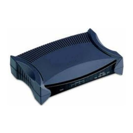
Before connecting any network device to the converter / Bridge, read this chapter carefully. 2.1 Front Panel The units’ front panel provides a simple interface monitoring the Ethernet over VDSL2 Converter. n DCE 5201V-BM Front Panel 5201V-BM 5201V-BM front panel Figure 2-1:... -
Page 13: Led Indicators For Dce 5201V-Bm
DCE 5204V-BM Front Panel 5204V-BM 5204V-BM front panel Figure 2-2: 2.1.1 LED indicators for DCE 5201V-BM The rich diagnostic LEDs on the front panel can provide the operating status of individual port and whole system. n System Color Function Lights to indicate that the VDSL Converter has power. -
Page 14: Led Indicators For Dce 5204V-Bm
n 10/100Base-TX Port Color Function Indicate that the port is link up. Indicate that the VDSL Converter is LNK/ Green Blink actively sending or receiving data over that port. Indicate that the port is link down. Indicate that the port is operating at 100Mbps. - Page 15 n VDSL Color Function Indicate that the VDSL link is established. Fast Indicate that the VDSL link is at training VDSL Green Blink status (about 10 seconds). Slow Indicate that the VDSL link is at idle Blink status. Indicate the VDSL Bridge is running at Green CO mode.
-
Page 16: The Rear Panel
2.2 The Rear Panel The rear panel of the Ethernet over VDSL2 Converter is shown as below. n DCE 5201V-BM Rear Panel 1 2 3 4 5201V-BM rear panel Figure 2-3: n DCE 5204V-BM Rear Panel 1 2 3 4... - Page 17 n DIP-1: Mode (CO/CPE) CO (Central Office) – the Master device mode, usually the CO device will be located at the data center of ISP or enterprise to link to the backbone. CPE (Customer Premises Equipment) – the Slave device mode, usually the CPE device will be located at branch office, home or remote side as the long reach data receiver.
-
Page 18: Dc Power Jack
1. By default, the four DIP switch are at “ON” position that will operate as “CPE”. For operate as “CO”, please adjust the DIP 1 switch at “OFF” position. Then adjust other DIP switch accordingly to fulfill different network applica- tion demand. -
Page 19: Installing And Using Vdsl Converter
Slave device) and allows data and voice work on the same telephone lines. DCE 5201V-BM provides one RJ-11 connector for VDSL port and the port can build VDSL2 connection easily. For voice device connection, the additional splitter from 5201V-BM package is an idea choice. -
Page 20: 5201/4V-Bm Lan To Lan Connection
3.1.1 DCE 5401V-BM LAN to LAN connection Two sets of the Ethernet over VDSL2 Converters / Bridge could be used to link two local Area networks that are located in different place. Through the normal telephone line, it could setup a 100/100Mbps symmetric backbone, but one Ethernet over VDSL2 Converters / Bridge must be Master (CO mode) and the other one is Slave (CPE mode). -
Page 21: 520Xv-Bm Connect To Multi-Port Master
3.1.2 520XV-BM Connect to Multi-Port Master In order, to built up a local Internet in apartment, hotel and campus and hospitality environment. The Multi-port Master (for example, 5208-SW / 5224-SW VDSL2 Switch) need to be placed in the wiring center (MDF room) and connect to the telephone line system, on the other hand, need to install a Slave (520XV-BM) Converters / Bridge on the individual client side and connect to the Multi-port Master... -
Page 22: Connecting Dce 520Xv-Bm
3.2 Connecting 520XV-BM 3.2.1 Connecting Standalone PC Refer to the following procedures to setup the 5201V- BM to a standalone PC. 1. Set the 5201V-BM to be CO mode or CPE mode from the DIP switch at the rear panel. 2. -
Page 23: Connecting Multiple Pcs To An Ethernet Lan
3.2.2 Connecting Multiple PCs to an Ethernet LAN Refer to the following procedures to setup the 520XV-BM to an Ethernet LAN. 1. Set the 520XV-BM to be CO mode or CPE mode from the DIP switch at the rear panel. 2. - Page 24 RJ-11 Line Cord Phone RJ-11 Line Cord RJ-11 Phone Jack 5201V-BM RJ-45 Cat.5 Switch Twisted Pair Cable IP Cam Wireless Laptop IP TV 100Base-TX UTP Telephone wire RJ-11 Phone Wire RJ-11 Phone Wire RJ-11 Phone Jack Phone 5204V-BM 1 2 3 4 IP Cam IP TV Wireless...
-
Page 25: Chassis Installation And Rack Mounting (520Xv-Bm)
3.3 Chassis Installation & Rack Mounting (5201V- To install the Ethernet over VDSL2 Converter in a 10-inch or 19-inch Converter Chassis with standard rack, follow the instructions described below. Step 1: Place your 5201A-BM on a hard flat surface, with the front panel positioned towards your front side. -
Page 26: Power Information
4. Power Information The power jack of 520XV-BM is with 2.5mm in the central post and required +5VDC power input. It will conform to the bundled AC-DC adapter and Planet’s Media Chassis. Should you have the issue to make the power connection, please contact your local sales representative. -
Page 27: Troubleshooting
5. Troubleshooting SYMPTOM: VDSL LNK LED does not light after wire is connected to the VDSL port. CHECKPOINT: 1. Verify the length of the wire connected between two 520XV-BM is not more than 1.4km. Please also try to adjust the DIP switch or 520XV-BM to other SNR mode. -
Page 28: Faq
6. FAQ Q1: What is the voltage that the 520XV-BM uses? A1: 5V DC, 2A Q2: What is VDSL2? A2: VDSL2 (Very High-Bit-Rate Digital Subscriber Line 2), G.993.2 is the newest and most advanced standard of xDSL broadband wire line communications. Designed to support the wide deployment of Triple Play services such as voice, data, high definition television (HDTV) and interactive gaming, VDSL2 enable operators... - Page 29 Ratio, often written SNR, is a measure of signal strength relative to background noise. The ratio is usually measured in decibels (dB). In digital communications, the SNR will probably cause a reduction in data speed because of frequent errors that require the source (transmitting) computer or terminal to resend some packets of data.
- Page 30 This page is intentionally left blank...
- Page 31 This page is intentionally left blank...
- Page 32 This page is intentionally left blank...
Need help?
Do you have a question about the DCE 5201V-BM and is the answer not in the manual?
Questions and answers