Table of Contents
Advertisement
Quick Links
I-C13 Impactor
Operating and Maintenance Manual
Manufactured by:
Address:
Telephone:
Fax:
Parts and Service:
www:
Ver: IC13-EN-10567
Extec Screens & Crushers Ltd
Hearthcote Road
Swadlincote
Derbyshire
DE11 9DU
United Kingdom
+44 (0)1283 212121
+44 (0)1283 226465
+44 (0)8000 181945
http://www.extecscreens.com
Operating and Maintenance Manual
19 June 2007
Advertisement
Chapters
Table of Contents

Subscribe to Our Youtube Channel
Related Manuals for Extec I-C13 Impactor

Summary of Contents for Extec I-C13 Impactor
- Page 1 I-C13 Impactor Operating and Maintenance Manual Manufactured by: Extec Screens & Crushers Ltd Address: Hearthcote Road Swadlincote Derbyshire DE11 9DU United Kingdom Telephone: +44 (0)1283 212121 Fax: +44 (0)1283 226465 Parts and Service: +44 (0)8000 181945 www: http://www.extecscreens.com Ver: IC13-EN-10567...
-
Page 2: Introduction
A copy of this manual must be kept at the operational site for easy reference. Extec Screens & Crushers Ltd reserve the right to change the content of this manual without prior notice. The information contained within this manual should be considered to be commercially confidential and should not be released to any third party without prior consent from Extec Screens &... -
Page 3: Certificate Of Conformity
I-C13 Impactor Certificate of Conformity Supply of Machinery Safety Regulations - Machinery Directive 98/37/EC Serial No: Engine Serial No: Production Manager: Date of build: Issued Declaration of Conformity on next page. Ver: IC13-EN-10567 Certificate of Conformity Page iii... - Page 4 I-C13 Impactor 98/37/EC Machinery 89/336/EEC EMC Name of manufacturer or supplier Extec Screens & Crushers Ltd Full postal address including country of origin Hearthcote Road, Swadlincote, Derbyshire, England, DE11 9DU Description of product Impactor Name, type or model, batch Impactor Extec Screens &...
-
Page 5: Table Of Contents
I-C13 Impactor Contents Operating and Maintenance Manual Introduction ..............ii Certificate of Conformity . -
Page 6: Contents
Key Features of the I-C13 Impactor ....... . . 20... - Page 7 I-C13 Impactor 4.8.2 Operation of the Recirculation Unit ......43 Operating The Machine ......... . . 44 4.9.1 Operating Starting Sequence .
- Page 8 I-C13 Impactor Magnetic Conveyor and Supports ........85 Power Pack .
- Page 9 I-C13 Impactor IMPACTOR BOX MANUAL Appendix D Hazardous Substances associated with this machine . . . 209 Exxon Unirex N 3 Grease......570317-00 UNIREX N 3 Shell Albida Grease EP2 .
- Page 10 I-C13 Impactor Page x Contents Ver: IC13-EN-10567...
-
Page 11: Safety Instructions
I-C13 Impactor Section 1 Safety Instructions Notes Read this manual and familiarise yourself with any associated documentation. Ensure that a copy of this manual is available for any persons installing, using, maintaining or repairing this equipment. Training should be provided to ensure safe working practices. Initial commissioning and starting must only be undertaken by a competent person who has read and fully understands the information provided in the manual pack. -
Page 12: Warnings Marked On The Machine
I-C13 Impactor Warnings marked on the machine The following labels are posted on the machine for your safety. Please observe all warnings. • You can be injured if you do not obey the safety instructions as indicated on warning stickers. - Page 13 I-C13 Impactor Ver: IC13-EN-10567 Safety Instructions Page 3...
- Page 14 I-C13 Impactor Page 4 Safety Instructions Ver: IC13-EN-10567...
-
Page 15: Machine Safety Warnings
I-C13 Impactor 1.3.2 Machine Safety Warnings 1.3.3 Machine Legend Plate Component Safety Features Do not use this equipment with guards removed or incorrectly fastened. Do not use this equipment with safety devices maladjusted or removed. Ver: IC13-EN-10567 Safety Instructions Page 5... -
Page 16: Features For Operator Safety
I-C13 Impactor Features for Operator Safety Safety features associated with this equipment have been assessed in accordance with BS EN 954-1 to Category 3. The Emergency Stop circuit is a 24 V DC series circuit and hard wired to remove power from the ECU Engine management system and stop the engine. -
Page 17: Machine Disposal
I-C13 Impactor • Ensure that all consumables and replaced parts are disposed of safely and with minimum environmental impact. 1.6.2 Machine Disposal • This machine must only be disposed of at a specialist machine breaker. Personal Protective Equipment (PPE) Loose or baggy clothing can get caught in running machinery. -
Page 18: Measured Noise Level
I-C13 Impactor Measured Noise Level Figure 1-1: Measured Noise Level The above diagram indicates the measured noise levels at a measured distance. i.e. 7 m - 85 dB indicates that at 7 meters the sound measured was 85 decibels. The readings were measured using a Castle GA101/701 meter with a calibration date of 05/06/04 and with all systems running situated on the factory assembly line. -
Page 19: Personnel Qualification, Requirements And Responsibilities
I-C13 Impactor and operate controls to relieve pressure. Stop the engine. Implement lockout procedures. Allow the machinery to cool. • Keep all parts in good condition. Ensure that all parts are properly installed. Fix damage immediately. Replace worn and broken parts. Remove any build up of grease, oil and debris. -
Page 20: Blockage Or Malfunction
I-C13 Impactor 1.12.2 Blockage or Malfunction In the event of material blockage, any malfunction or operational difficulty, stop the plant immediately and lockout. Have any defects rectified immediately. 1.12.3 Unguarded Areas • In-running nip points on moving machinery can cause serious injury or even death. -
Page 21: Climbing, Falling
To avoid the risk of accidents, individual parts and large assemblies being moved for replacement purposes should be carefully attached to lifting tackle and secured. Use only suitable and technically adequate lifting gear supplied or approved by Extec Screens & Crushers Ltd. -
Page 22: Safety Considerations During Cleaning
I-C13 Impactor • The fastening of loads and instructing of crane operators should be entrusted to qualified persons only. • The marshal providing instructions must be within sight or sound of the operator with an all round view of the operation. -
Page 23: Specific Hazards
I-C13 Impactor • Never add gasoline or any other fuels mixed to diesel because of increased fire or explosion risks and damage to the engine. • Do not carry out maintenance on the fuel system near naked lights or sources of sparks, such as welding equipment or whilst smoking. -
Page 24: Battery
I-C13 Impactor Battery • Always disconnect battery leads before carrying out any maintenance to the electrical system. • Recharge the battery in a well ventilated area. • The battery contains sulphuric acid, an electrolyte which can cause severe burns and produce explosive gases. -
Page 25: Hazardous Substances
I-C13 Impactor Depressurise all system sections and pressure pipes (hydraulic system, compressed air system) to be removed in accordance with the specific instructions for the unit concerned before carrying out any repair work. Hydraulic and compressed air lines must be laid and fitted properly. Ensure that no connections are interchanged. - Page 26 I-C13 Impactor Intentionally left blank Page 16 Safety Instructions Ver: IC13-EN-10567...
-
Page 27: Transportation
I-C13 Impactor Section 2 Transportation Transport This machine must only be transported between sites on a suitable low loader or by utilising the optional bogie/ fifth wheel where available. The machine must be tracked onto and off the trailer. See “Tracking Procedure” on page 33. -
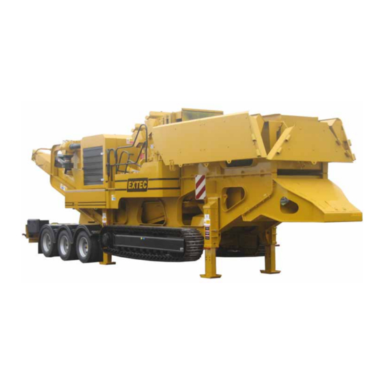
Page 28: Machine Transportation Dimension
I-C13 Impactor Machine Transportation Dimension Figure 2-1: I-C13 Impactor Transport Dimensions Figure 2-2: I-C13 Impactor Transport Dimensions Including Bogie and Swan Neck Ensure the exhaust stack and spray bar are folded down and the apron adjuster caps are removed for transportation. -
Page 29: Description And Technical Information
The I-C13 Impactor is a self contained tracked machine built to withstand the rigours and conditions of operating in quarries and within the construction industry. The I-C13 Impactor utilises a diesel engine to provide the power to the hydraulic power pack and to generate electricity for the electrical systems of the machine. -
Page 30: Key Features Of The I-C13 Impactor
The material continues along the main conveyor where it is unloaded to a pile or to waiting transport. Key Features of the I-C13 Impactor • Diesel hydraulic power via Caterpillar C-13 Industrial C 440 bhp engine providing hydraulic transmission without clutches. -
Page 31: Machine Layout Indicating Main Components
I-C13 Impactor • Asphalt This list is by no means exhaustive. Please contact Extec Screens & Crushers Ltd for further details of performance figures and advice on your material. Machine Layout Indicating Main Components IMPACTOR POWER PACK MAIN CONVEYOR HOPPER... -
Page 32: Emergency Stop Positions
I-C13 Impactor Emergency Stop Positions Figure 3-2: Emergency Stop Positions Data Crusher Feed Opening 1290 x 950 mm Crusher Speed 500 - 765 rpm Drive Hydraulic Feeder Hopper Width 2751 mm Feeder Width 1100 mm Feeder Length 4000 mm Hopper Capacity 5.3 cubic meters... -
Page 33: Dimensions
I-C13 Impactor Main Conveyor 1000 x 10000 mm Main Conveyor Speed 123 rpm Dimensions Transport Length 14143 mm Transport Width 2756 mm Transport Height 3911 mm Working Length 14017 mm Working Width 4107 mm Working Height 4023 mm Weight 44 000 kg... -
Page 35: Commissioning And Operation
I-C13 Impactor Section 4 Commissioning and Operation Pre-Start Instructions Before starting this machine it is important that the instructions below are followed: Ensure that this manual is read and understood. Do not attempt to start this machine until you are aware of all aspects of its operation. -
Page 36: Main Control Devices
I-C13 Impactor Main Control Devices Figure 4-1: Electrical Control Box Emergency Stop Ignition Key (ON/OFF) Engine Warning Lights Engine Speed Control Diagnostic Lamp Warning Lamp Engine rpm Meter Interlock (ON/OFF) Main Conveyor (ON/OFF) Side Conveyor (ON/OFF) Magnet (ON/OFF) Crusher (ON/OFF) - Page 37 Ignition Switch Position Figure 4-3: Engine Warning Lights The I-C13 Impactor is equipped with a safety shutdown control panel. With this type of system, built-in switches set to factory preset limits, operate such that if during operation, either the oil pressure or engine temperature reaches its preset limit, the system will experience a safety shutdown and turn the engine off.
-
Page 38: Starting Procedure
I-C13 Impactor Starting Procedure Figure 4-4: Starting procedure Turn on at main isolation switch (1) positioned in the hydraulic control box next to the battery. Set the speed control (2) to the No.1 position. Turn the key (3) clockwise to the “ON” position. All lights will flash for several seconds. -
Page 39: Stopping Machine In An Emergency
I-C13 Impactor Impactor Main conveyor Magnet Side conveyor Recirculation conveyor (Where fitted) Wait for each system to come to a complete stop. Turn engine speed switch to position No.1 and allow engine to idle briefly. Stop engine by turning ignition key to 'OFF' position. -
Page 40: Removing Tractor Unit And Bogie - (Where Fitted)
I-C13 Impactor Removing Tractor Unit and Bogie - (Where fitted) 1: Remove jacking leg retention screws. Note: Before attempting to lower the jacking legs ALL of the leg transportation retaining screws MUST be removed. 3: Lower front jacking legs to raise fifth wheel 2: Front jacking legs lever. - Page 41 I-C13 Impactor 7: Lower rear jacking legs to raise machine 6: Rear jacking legs lever. clear of the bogie locking mechanism. 8: Remove bogie air brakes & lighting 9: Retract both front and rear jacking legs so connections then tow away from machine.
- Page 42 I-C13 Impactor 12: Hopper back door being raised. 13: Raise hopper back door. 14: Hopper back door being raised. 15: Hopper sides fully raised. 16: Remove connection panel & umbilical cord completely from machine. Fitting the bogie and attaching the tractor for transportation is a reversed procedure to that describe above.
-
Page 43: Tracking Procedure
I-C13 Impactor Tracking Procedure The operator must be fully trained in the operation of this equipment. When tracking, the operator must be in a position to have an all round view of the operation. A banks man or marshal should assist where this is not possible. - Page 44 (These correspond to direction indicator stickers on the machine.) DE1007 When the machine is moved to its desired operating position, prepare the I-C13 Impactor for operation by following the procedures laid out in the following pages. Page 34...
-
Page 45: Preparing The I-C13 Impactor For Operation
I-C13 Impactor Preparing the I-C13 Impactor for Operation 1: Press button "Interlock On". 2: Remove side conveyor locking pin. side con fold 3: Activate lever marked to lower 4: Side conveyor in working position. side conveyor. 5: Raise main conveyor spray bar to working 6: Fix main conveyor spray bar in working position. - Page 46 I-C13 Impactor 1: Replace apron adjuster caps removed & stored during transport. 2: Unfold ladder, ensuring its locked into 3: Lift rail into position and lock with pin. position. 4: Lift up rotating gate section. 5: Rotate & lower the gate into position. Repeat the procedure on other side of machine.
-
Page 47: Installation Of The Recirculation Unit (Where Fitted)
I-C13 Impactor 6: Lower rear jack legs by 7: Lower front jack legs by 8: Fit pins & R-clips to jack legs operating levers. operating levers. (8 off). Where a recirculation conveyor is fitted, the jacking leg levers are located in the hydraulic control cabinet. - Page 48 All adjustments must ONLY be carried out by trained personnel. All adjustments to modify hydraulic system must ONLY be carried out by trained Extec service engineers ONLY use appropriate lifting equipment to separate the different parts of the recirculation unit.
- Page 49 I-C13 Impactor 3: Remove the lock pins 4: Extend the support and install the pin Ver: IC13-EN-10567 Commissioning and Operation Page 39...
- Page 50 I-C13 Impactor 5: Install the main conveyor in position on the crusher 6: Use the lever to lower the hydraulic arms 7: Install the hydraulic arms on the supports 8: Attach the spacer bush and the motor 9: Install the hydraulic hose HH10158...
- Page 51 I-C13 Impactor 10: Install the hydraulic hoses to the side 11: Install the hydraulic hoses from their conveyor motor match marks 12: Install the support bracket box and attach 13: Put the recirculation conveyor in position the support bracket and attach the lower end to the support beam...
- Page 52 I-C13 Impactor 16: Install the screen mesh 17: Tighten the screen mesh with the handle To attach the recirculation conveyor perpendicular to the impactor do the steps that follow 18: Put the recirculation conveyor in position Page 42 Commissioning and Operation...
-
Page 53: Operation Of The Recirculation Unit
I-C13 Impactor 20: Attachment points of the recirculation 19: Attachment points of the chassis conveyor 21: Attach the two support cables to the impactor chassis and the recirculation conveyor 4.8.2 Operation of the Recirculation Unit Make sure that the Impactor is started “Starting Procedure” on page 28. -
Page 54: Operating The Machine
I-C13 Impactor 3: Use the lever to move the side conveyor 4: The side conveyor adjusted 5: Turn on the recirculation conveyors Operating The Machine 4.9.1 Operating Starting Sequence When the machine is set up as described in the previous pages, it is now ready to be operated. -
Page 55: Loading Material Into Machine
STOP MACHINE and remove any large pieces of material with the appropriate equipment. DO NOT use excavators to force any material into feeder as any damage occurred from this action will invalidate any Extec Screens & Crushers Ltd warrantees. -
Page 56: Feeder Cut-Out
DO NOT START CRUSHING UNTIL YOU HAVE READ AND FULLY UNDERSTOOD THIS MANUAL. 4.9.3 Feeder Cut-out The I-C13 Impactor is fitted with a pressure High Pressure sensing device that will cut out the operation of Feeder cuts out when... -
Page 57: Impactor Box Pressure Adjustment
I-C13 Impactor crusher chamber and reduces the amount of down time. Figure 4-6: Feeder cut out switch - on. Figure 4-7: Feeder cut out switch - off. 4.10 Impactor Box Pressure Adjustment SAFETY NOTICE The following procedures are carried out with the machine running so extra care MUST be taken to ensure the safety of ANY personnel on or in the vicinity of the machine. -
Page 58: Brake Pressure
I-C13 Impactor Note: The rotor will run for at least 20 seconds after stopping the box to allow for smooth braking. 4.10.2 Brake Pressure 3: Brake Pressure 4: Adjusting Pressure Attach pressure gauge to pressure point as shown. Start impactor box at full speed on No.2 (800 rpm) then stop impactor box. The pressure gauge should read 150 bar. -
Page 59: Machine Maintenance
DO NOT stand on any part of the engine whilst operating or carrying out any maintenance on the machine. All adjustments must ONLY be carried out by trained personnel. All adjustments to modify hydraulic system must ONLY be carried out by trained Extec service engineers. Daily Maintenance Schedule 1: Check engine oil level. - Page 60 I-C13 Impactor 4: Refill diesel tank using the diesel pump and 3: Check fuel level. fuel suction pipe. Alternatively refill manually after cleaning around the cap opening. 6: Check radiator water level & refill if 5: Bleed diesel water trap.
-
Page 61: Air Cleaner Servicing
I-C13 Impactor 5.2.1 Air Cleaner Servicing Check the service indicators on the air cleaner. Regardless of condition of service indicator, remove the primary air cleaner from air cleaner as shown below and clean using compressed air. Never clean the secondary air cleaner. After 3 primary air cleaner replacements, replace the secondary air cleaner. -
Page 62: Weekly Maintenance Schedule
I-C13 Impactor 5: Cover the turbocharger air inlet in order to keep 6: Replace air cleaners and cover after cleaning. dirt out. Clean the inside of the air cleaner cover Reset the air cleaner service indicator. and body with a clean, dry cloth. - Page 63 I-C13 Impactor Check the condition of conveyor belts, rollers and other moving parts. Clear any obstructions from the grizzly bars and impactor chamber. Check all bolts and panels are in place and secure. Clear any build up of dust from the oil cooler and radiator using compressed air.
-
Page 64: Checking Feeder Oil Level
I-C13 Impactor 5.3.1 Checking Feeder Oil Level 2: Remove oil filler plug. Refill using Shell Omala 220 Gear Oil until oil comes out of level 1: Remove oil level plug. If oil trickles out, there hole. is enough oil in feeder - if not, oil level needs to be topped up. -
Page 65: Checking/ Changing Hydraulic Tank Air Breather
5.3.3 Greasing Bearings Extec Screens & Crushers Ltd use SKF sealed-for-life bearings that reduce grease consumption, lower life cycle cost, lower recycling costs and reduce pressure on the environment. The results are dramatically increased up-time for the machines and the consequent reduction in maintenance costs. -
Page 66: Inspecting/ Adjusting Belt Sealing Rubbers
I-C13 Impactor Impactor Box Bearings Torque Arm See lubrication schedule Bearings in separate impactor 50 grams/ 40 hours box manual Grease LGHQ3/18 Feeder Unit Track Gear Boxes Fill to Oil Levels Fill to Oil Levels EP220 Gear Oil EP90 Gear Oil Figure 5-1: Grease Points 5.3.4 Inspecting/ Adjusting Belt Sealing Rubbers... -
Page 67: Hydraulic Filter
I-C13 Impactor 5.3.6 Hydraulic Filter Check service indicators on hydraulic filters when the machine is running. CHECKING CONDITION OF FILTER INDICATORS IS THE ONLY CHECK TO BE MADE WHEN MACHINE IS RUNNING. STOP MACHINE BEFORE REPLACING ELEMENTS. 1: Lift up cover & inspect service indicator. -
Page 68: Changing Hydraulic Water Trap
I-C13 Impactor 5.3.7 Changing Hydraulic Water Trap Note: When the water trap is taken off, oil will spill out. Use a suitable container to catch any waste oil - expect between 3 and 5 litres. Replace water trap as shown. -
Page 69: 1000 Hour Maintenance Schedule
I-C13 Impactor Check drive belts for wear, swelling, softening and tension. Replace if necessary. Note: Tension should remain constant during the belts working life and should not be re- tensioned. Clean out sediment bowl on fuel pre-filter. Note: When sediment bowl is cleaned out, the fuel system will have to be re-primed. - Page 70 I-C13 Impactor To refill track gearbox with oil, drive the machine until the gearbox is in the correct position. See below. Note: This will only be 1/3 turn of the track gearbox. DO NOT drive machine any further until oil has been replaced in tracks. Remove the oil level plug as shown in the photographs below.
-
Page 71: Track Adjustments
I-C13 Impactor Track Adjustments WARNING! Grease under pressure can cause serious injury. Never unscrew a track adjuster valve by more than a ½ turn, when the track is under tension. 5.6.1 Track Adjustment After maintenance or over time the track will become slack and will have to be adjusted. The adjustment of the tracks operates through a tensioning cylinder (C). -
Page 72: Increasing The Track Tension
I-C13 Impactor Note: It is also important that the track is not tensioned too tightly as this places excessive loads on the gearbox and idler bearings. It will also lead to accelerated wear and premature failures. 30 mm (Max) 2: Track Adjustment Settings 5.6.3 Increasing The Track Tension... -
Page 73: Releasing The Track Tension
I-C13 Impactor Important: Ensure that the correct grease is used. 3: Increasing The Track Tension 5.6.4 Releasing The Track Tension To the release the tension on the tracks: Remove the inspection cover on the side of the track frame as shown at (F). -
Page 74: Magnetic Conveyor
I-C13 Impactor Magnetic Conveyor WARNING: The machine MUST be switched off and ignition key removed BEFORE making any adjustments. Follow maintenance instructions laid out in the magnet manufacturer’s handbook. See “ERIEZ MAGNET MODELS CP & OP INSTRUCTIONS IM-108GB-(F.01)” on page 199. -
Page 75: Trouble Shooting Guide
I-C13 Impactor Section 6 Trouble Shooting Guide Below is a list of some of the common problems that might occur on your machine. If these problems arise, carry out the checks listed. PROBLEM SOLUTION Engine losing power or hard to Check air filter isn’t blocked. - Page 76 Check that all levers are in their central position and check if the crusher operates. If Crusher operates and levers are central but the machine still won't track, this may indicate an electrical problem. Contact Extec Screens & Crushers Ltd immediately. Main, Side or Magnet Conveyor Check belt tension.
-
Page 77: Checking Hydraulic Pressure
I-C13 Impactor Checking Hydraulic Pressure 3: Check tank return pressure 5: Check suction pressure using 4: Check control pressure using a using a 0 - 10 bar pressure a 0 - 6 bar pressure gauge - this 0 - 100 bar pressure gauge. This gauge - this should be not should be between ½... -
Page 78: Test Procedures For Electronics
I-C13 Impactor Test Procedures for Electronics See drawings in the Appendix B: Drawing Pack for lamp diagnostics, jaw control and wiring diagrams. Symptoms: Engine is shutting down and remote stop lamp on EPU is showing. The crusher electronics shuts down the engine via the EPU for 3 reasons: Signal received by receiver from correctly coded handset requesting “fast stop”. - Page 79 Check these wires to ensure they are not swapped or poorly crimped. IF ANY PROBLEM PERSISTS AFTER CARRYING OUT THE RECOMMENDED SOLUTION, OR A PROBLEM ARISES THAT IS NOT ON THIS LIST, CONTACT Extec Screens & Crushers Ltd SERVICE DEPARTMENT FOR FURTHER ASSISTANCE.
- Page 80 I-C13 Impactor Intentionally left blank Page 70 Trouble Shooting Guide Ver: IC13-EN-10567...
-
Page 81: Appendix A Parts Manual
I-C13 Impactor Appendix A Parts Manual Contact Details Extec Screens & Crushers Ltd Hearthcote Road Swadlincote Derbyshire DE11 9DU United Kingdom Telephone: +44 (0)1283 212121 Fax: +44 (0)1283 226465 Parts and Service: +44 (0)8000 181945 www: http://www.extecscreens.com Ver: IC13-EN-10567 Appendix A... - Page 82 Note: Every effort has been made to ensure the accuracy of this manual at the time of publication. However, with Extec Screens & Crushers Ltds' policy of continually improving their products, your machine may not coincide exactly with this manual.
-
Page 83: Parts Manual Contents
I-C13 Impactor Parts Manual Contents Loose Items ........... . . 74 Chassis, Walkways and Tracks . -
Page 84: Loose Items
I-C13 Impactor AA.1 Loose Items 1: LOOSE ITEMS Part No. Part Description Quantity EL2069 MANUAL HANDSET EL2009 UMBILICAL CHORD (7 m) EL2104 REMOTE CONTROL HANDSET CHARGER (UK ONLY) EL2105 REMOTE CONTROL HANDSET CHARGER (CONTINENT ONLY) EL2106 REMOTE CONTROL HANDSET CHARGER (JAPAN ONLY) - Page 85 I-C13 Impactor Part No. Part Description Quantity EL2109 REMOTE CONTROL HANDSET CHARGER (USA ONLY) EL2110 JAW ADJUST REMOTE CONTROL EL4418 REMOTE CONTROL HANDSET (433 MHz) EN4420 FEEDER REMOTE CONTROL HAH101401 FUEL SUCTION PIPE IM1036 LIFTING GEAR PN1088 JACKING LEG SUPPORT PINS...
-
Page 86: Chassis, Walkways And Tracks
I-C13 Impactor AA.2 Chassis, Walkways and Tracks 1: CHASSIS ASSEMBLY 2: CHASSIS FRONT END 3: CHASSIS REAR END Page 76 Chassis, Walkways and Tracks Ver: IC13-EN-10567... - Page 87 I-C13 Impactor 4: JACKING LEG 5: JACKING LEG MOUNTED 6: WALKWAY Ver: IC13-EN-10567 Chassis, Walkways and Tracks Page 77...
- Page 88 I-C13 Impactor 7: PULLEY GUARD 8: PULLEY GUARDS REAR Page 78 Chassis, Walkways and Tracks Ver: IC13-EN-10567...
- Page 89 I-C13 Impactor 9: RECIRCULATION CHASSIS ASSEMBLY Part No. Part Description Quantity A4110000 JACKING LEG INNER A6160000 JACKING LEG COVER REAR LEFT A6620000 IMPACTOR PULLEY INNER GUARD A6620600 BRACKET A6620700 BRACKET A6630000 IMPACTOR PULLEY OUTER GUARD A6640000 IMPACTOR PULLEY SPLIT COVER TOP...
- Page 90 I-C13 Impactor Part No. Part Description Quantity A14200000 WALKWAY BRACKET A14460000 JACKING LEG COVER A14710000 MAGNET SUPPORT R/H A14720000 MAGNET SUPPORT L/H A14840000 WALKWAY ASSEMBLY NON-DRIVE SIDE A14880000 WALKWAY END RAILING (LARGE R/H) A14900000 WALKWAY RAILING A14910000 WALKWAY RAILING A14940000...
-
Page 91: Tracks
I-C13 Impactor AA.3 Tracks Hidden 1: VIEW OF TRACKS Part No. Part Description Quantity A13920000 TRACK FRAME MOUNTING BOGIE A13930000 TRACK DOWEL A15910000 TRACK FRAME MOUNTING BOGIE (REPLACE 1 FOR RECIRCULATION MACHINE) FAB1009 3/4 UNC X 3½” BOLT [8.8] FAB16X45 M16 X 45 BOLT FAB20X60(10.9) - Page 92 I-C13 Impactor Part No. Part Description Quantity R0800000 CONE TRACKS BODY ASSEMBLY R/H R0810000 CONE TRACKS BODY ASSEMBLY L/H R0820000 TRACK MOTOR HOUSING COVER PLAT R0840000 TRACK CHAIN GUIDE DTL UC2020 TRACK COMPLETE UC3950 PC395 TRACK ROLLERS-C12 [18 PER PAIR]...
-
Page 93: Hopper
I-C13 Impactor AA.4 Hopper 1: HOPPER DOORS 2: HOPPER RAMS Ver: IC13-EN-10567 Hopper Page 83... -
Page 94: Hopper
I-C13 Impactor Part No. Part Description Quantity A15190000 FEEDER FRAME A15200000 GUARD C1020000 HOPPER DOOR TIE BAR C1080000 HOPPER REAR DOOR RAM SHIELD C9250000 HOPPER R/H SIDE DOOR C9260000 HOPPER L/H SIDE DOOR C9270000 HOPPER REAR DOOR C9280000 HOPPER FRONT SIDE LINER PLATE: 10mm M/S... -
Page 95: Magnetic Conveyor And Supports
I-C13 Impactor AA.5 Magnetic Conveyor and Supports 1: MAGNETIC CONVEYOR FITTED 2: MAGNETIC CONVEYOR Part No. Part Description Quantity A8880000 MAGNET SUPPORT FRAME (DRIVE SIDE) A8890000 MAGNET SUPPORT FRAME FAEB1002 M24 LIFTING EYE HM1010 BELT DRIVE MOTOR 305 cc MA1001... -
Page 96: Power Pack
I-C13 Impactor AA.6 Power Pack Hidden Hidden 1: R/H VIEW OF POWER PACK Hidden Hidden 2: L/H VIEW OF POWER PACK Page 86 Power Pack Ver: IC13-EN-10567... - Page 97 I-C13 Impactor 3: VIEW ON BOTTOM OF POWER PACK Hidden 4: HYDRAULIC TANK Ver: IC13-EN-10567 Power Pack Page 87...
- Page 98 I-C13 Impactor 5: HYDRAULIC TANK - BELOW RETURN FILTERS Page 88 Power Pack Ver: IC13-EN-10567...
- Page 99 I-C13 Impactor 7: VIEW ON AIR FILTER 8: VIEW ON VALVE PLATE ASSEMBLY Ver: IC13-EN-10567 Power Pack Page 89...
- Page 100 I-C13 Impactor 9: VIEW ON SOLENOID VALVE 10: VIEW ON 5 STATION MANIFOLD BLOCK 11: HYDRAULIC WATER TRAP 12: VIEW ON TOP OF POWER PACK 13: VIEW INSIDE POWER PACK Page 90 Power Pack Ver: IC13-EN-10567...
- Page 101 I-C13 Impactor Hidden 14: VIEW ON SUCTION PIPE 15: OIL COOLER - OPTIONAL 16: ACCESS DOOR TO VALVE PLATE Part No. Part Description Quantity A4870000 PACKER A16510000 PIPE TRAY B1300000 HYDRAULIC TANK LID B1310000 HYDRAULIC TANK LID B2410000 HYDRAULIC TANK LID GASKET...
- Page 102 I-C13 Impactor Part No. Part Description Quantity B6800000 POWER PACK ASSY B6810000 HYDRAULIC TANK B6820000 POWER PACK INFILL PANEL ASSY B6830000 POWER PACK CALVE PLATE ACCESS DOOR ASSY B6840000 POWER PACK BELLY PANEL B6850000 POWER PACK DOOR B6860000 C13 BISHOP HAT MESH...
- Page 103 I-C13 Impactor Part No. Part Description Quantity EN1404 HYDRAULIC WATER TRAP EN1504 VISUAL POP UP INDICATOR EN1505 VISUAL POP UP INDICATOR EN1523 DESECANT AIR BREATHER EN1601 LOCKABLE FILLER CAP0 EN2028 CFK-200-14-64225 C13/BOSCH ENG EN5025 VORTEX PRE CLEANER EN7705 C13 CATERPILLAR ENGINE...
- Page 104 I-C13 Impactor Part No. Part Description Quantity FAHC1063 BAND CLAMP 150 MM - 162 MM HAN100001 1¼" FLANGE CFS104 HAN100002 1" BSP SAE3000 FLANGE + BOLTS HAN100008 1½" BSP SAE6000 HAN100009 1½" BSP SAE 6000 FLANGE HAN100010 2" BSP SAE 3000 FLANGE...
-
Page 105: Control Boxes
I-C13 Impactor AA.7 Control Boxes 1: ELECTRICAL CONTROL BOX 2: HYDRAULIC CONTROL BOX Ver: IC13-EN-10567 Control Boxes Page 95... -
Page 106: Control Boxes
I-C13 Impactor Hidden 3: RECIRCULATION CONTROL BOX (WHERE FITTED) 4: VIEW ON ISOLATION SWITCH AND 5: VIEW ON WATER MANIFOLD BATTERIES Page 96 Control Boxes Ver: IC13-EN-10567... - Page 107 I-C13 Impactor 6: VIEW ON ACCUMULATOR PRESSURE GAUGES 7: VIEW ON PRESSURE SWITCHES Part No. Part Description Quantity A5020000 WATER MANIFOLD A6590000 BATTERY ISOLATING BRACKET A7700000 SPOOL INDICATOR A7710000 MOUNTING PLATE A7820000 CONTROL BOX LID A8850000 LYNCH PIN A10630000 EMERGENCY STOP GUARD...
- Page 108 I-C13 Impactor Part No. Part Description Quantity EL3001 HEAVY DUTY BATTERY EL3004 POSITIVE LEAD EL3005 NEGATIVE LEAD EL3010 BATTERY CROSSOVER FD1007 GAS STRUT (ONE EYE) FD2006 CHROME PULL HANDLE FD2109 POLIALL HINGE HV1020 4 LEVER SPOOL VALVE HV1049 6 LEVER SPOOL VALVE...
-
Page 109: Diesel Tank
I-C13 Impactor AA.8 Diesel Tank 1: DIESEL TANK ASSEMBLY 2: VIEW ON BOTTOM OF DIESEL TANK Part No. Part Description Quantity A10800000 DIESEL PUMP GUARD A12500000 DIESEL TANK A12510000 DIESEL TANK LID A12530000 DIESEL TANK STRAPS A14040000 DIESEL TANK PLATFORM... -
Page 110: Feeder And Vibrator Box
I-C13 Impactor AA.9 Feeder and Vibrator Box 1: FEEDER ASSEMBLY - VIEW ON TOP FROM MOTOR SIDE 2: FEEDER ASSEMBLY - VIEW FROM BOTTOM FROM GEAR SIDE Page 100 Feeder and Vibrator Box Ver: IC13-EN-10567... - Page 111 I-C13 Impactor 3: VIEW ON BOTTOM FROM MOTOR SIDE 4: VIEW ON MOTOR AND COVERS 5: GEAR SIDE WITHOUT GEARS FITTED 6: VIEW ON BEARING CARTRIDGE 7: GEAR SIDE GEARS FITTED 8: VIEW ON GEAR SIDE WITH COVER Ver: IC13-EN-10567...
-
Page 112: Feeder And Vibrator Box
I-C13 Impactor 9: VIBRATOR BOX - INSIDE 10: VIBRATOR BOX - MOTOR SIDE 11: VIBRATOR BOX - MOTOR SIDE 12: VIBRATOR BOX - MOTOR SIDE 13: VIBRATOR MOTOR ASSEMBLY 14: VIEW ON FEEEDER SUPPORT SPRINGS Page 102 Feeder and Vibrator Box... - Page 113 I-C13 Impactor Part No. Part Description H2700000 FEEDER H2770000 GRIZZLY BAR H1910000 FEEDER MOTOR GUARD H2000000 VIBRATOR HOUSING ASSEMBLY H2160000 MOTOR END COVER - DRIVE H2760000 FEEDER OUTLET CHUTE - REAR SECTION H2540000 FEEDER OUTLET CHUTE SIDE JOINT PLATE H1900000...
- Page 114 I-C13 Impactor Part No. Part Description BT8506 O-RING - DIA . 3.5mm BT8006 OIL SEAL H2720000 FEEDER OUTLET CHUTE - FRONT SECTION H2750000 WEAR PLATE - R.H.S BT6514 SPIDER BT5020 TAPER LOCK BUSH H2310000 FEEDER WEAR PLATE H2730000 OUTLET WEAR PLATE H2740000 WEAR PLATE - L.H.S...
-
Page 115: Transfer Chute
I-C13 Impactor AA.10 Transfer Chute 1: TRANSFER CHUTE ASSEMBLY 2: VIEW ON DISCHARGE END Ver: IC13-EN-10567 Transfer Chute Page 105... - Page 116 I-C13 Impactor 3: OPPOSITE HAND TRANSFER CHUTE ASSEMBLY 4: TRANSFER CHUTE TUBBER Page 106 Transfer Chute Ver: IC13-EN-10567...
-
Page 117: Transfer Chute
I-C13 Impactor Part No. Part Description Quantity A4650000 TRANSFER CHUTE DEFLECTOR PLATE A6150000 TRANSFER CHUTE RUBBER CLAMP A6430000 CHUTE SIDE CONVEYOR RUBBER A9840000 TRANSFER CHUTE A9850000 TRANSFER CHUTE COVER PLATE A9860000 IMPACTOR CHUTE RUBBER CLAMP A10160000 TRANSFER CHUTE REAR CLAMP... -
Page 118: Crusher Box
I-C13 Impactor AA.11 Crusher Box 5: View on Pulley Guard With Door Open 6: Detail View on Pulley Wheels 7: Detail View on Pulley Wheels Page 108 Crusher Box Ver: IC13-EN-10567... - Page 119 I-C13 Impactor 8: View on Torque Arm and Crusher Drive Motor 9: Inlet to Crusher Box Viewed From Feeder Ver: IC13-EN-10567 Crusher Box Page 109...
- Page 120 I-C13 Impactor 10: HYDRAULIC CONTROL BOX 11: HYDRAULIC CONTROL BOX Page 110 Crusher Box Ver: IC13-EN-10567...
- Page 121 12: Side Rubber Clamp Note: FOR FURTHER DETAILS OF PARTS WITHIN THE IMPACT CRUSHER BOX, SEE SEPARATE HAZEMAG PARTS & MAINTENANCE MANUAL SUPPLIED IN CONJUNCTION WITH THIS PARTS MANUAL. IF REQUIRED, CONTACT EXTEC SERVICE DEPARTMENT FOR FURTHER ASSISTANCE. Part No. Part Description...
- Page 122 I-C13 Impactor Part No. Part Description J5470000 CRUSHER BOX WEAR PLATE (SPARES ONLY) J5480000 CRUSHER BOX SIDE RUBBER CLAMP OUTER J3630000 CRUSHER INLET TOP RUBBER CLAMP PLATE J5620000 SIDE RUBBER CLAMP SPACER BT4035 SPC PULLEY BT4040 SPC PULLEY BT4506 SPC4750 PULLEY BELT...
-
Page 123: Torque Arm Assembly
I-C13 Impactor AA.12 Torque Arm Assembly 1: TORQUE ARM ASSEMBLY Part No. Part Description Quantity A6610000 MOUNTING PIN A13580000 BASE PLATE BT3015 INNER BEARING BT3016 OUTER BEARING BT5017 TAPER LOCK BUSH 50/50-100 BT4040 400 X 10 SPC PULLEY BT5504 LUBRICATING NIPPLE... - Page 124 I-C13 Impactor Part No. Part Description Quantity J8400000 MOTOR CONTROL BLOCK J0250000 PIN CAP J0330000 OUTER BEARING CAP J0820000 INNER BEARING SPACER RING J0930000 TENSIONING FRAME J5050000 PULLEY SHAFT J6970000 TURN BUCKLE Page 114 Torque Arm Assembly Ver: IC13-EN-10567...
-
Page 125: Main Conveyor
I-C13 Impactor AA.13 Main Conveyor 1: MAIN CONVEYOR TOP SECTION 2: VIEW ON FEED BOOT Ver: IC13-EN-10567 Main Conveyor Page 115... -
Page 126: Main Conveyor
I-C13 Impactor 3: VIEW OF REAR ROLLERS 4: VIEW ON MID SECTION Page 116 Main Conveyor Ver: IC13-EN-10567... - Page 127 I-C13 Impactor 5: MAIN CONVEYOR TOP SECTION 6: VIEW ON HEAD DRUM SCRAPER Ver: IC13-EN-10567 Main Conveyor Page 117...
- Page 128 I-C13 Impactor 7: DRIVE COUPLING Part No. Part Description Quantity BT1010 BEARING PLUMMER SY60TF BT2010 BEARING FLANGE FY60TF BT5009 2517/40 TAPER LOCK BUSH BT5011 2517/55 TAPER LOCK BUSH BT6516 TX180 DRIVE COUPLING INSERT BT6517 TX180F DRIVE COUPLING COMPLETE CBHD160001000 CONVEYOR BELT...
- Page 129 I-C13 Impactor Part No. Part Description Quantity CR1043 IMPACT ROLLER D0100000 MAIN CONV TAIL DRUM ASSEMBLY D0140000 MAIN CONV DRIVE DRUM ASSEMBLY D0180000 MC MTR MTG BRKT D0190000 MC MTR MTG COVER PLATE D1460000 MCONV FEED BOOTCLAMP D1790000 SPRAY BAR ASSY...
- Page 130 I-C13 Impactor Part No. Part Description Quantity D8420000 MC FEED BOOT GD L/H D8430000 ALUMINIUM CHUTE D11810000 CONVEYOR FLARE D11820000 CLAMP PLATE HA99000010 DXF1235T1 30° FULL CONE TIP HA99000011 ZLA2358T1 ¼ X 3/8" THREADED HA99000012 VAA0038T1 3/8” BRASS RETAINING HA99000013 ZPF0125D6 1½”...
-
Page 131: Extended Main Conveyor (Where Fitted)
I-C13 Impactor AA.14 .Extended Main Conveyor (Where fitted) 1: EXTENDED MAIN CONVEYOR ASSEMBLY 2: VIEW ON CONVEYOR HEAD DRUM Ver: IC13-EN-10567 .Extended Main Conveyor (Where fitted) Page 121... -
Page 132: Extended Main Conveyor (Where Fitted)
I-C13 Impactor 3: VIEW ON CONVEYOR TOP SECTION 4: VIEW ON MIDDLE SECTION Page 122 .Extended Main Conveyor (Where fitted) Ver: IC13-EN-10567... - Page 133 I-C13 Impactor 5: VIEW ON TAIL DRUM 6: VIEW UNDERNEATH CONVEYOR Ver: IC13-EN-10567 .Extended Main Conveyor (Where fitted) Page 123...
- Page 134 I-C13 Impactor 7: VIEW ON DRIVE COUPLING 8: VIEW ON TOP SECTION Page 124 .Extended Main Conveyor (Where fitted) Ver: IC13-EN-10567...
- Page 135 I-C13 Impactor Hidden 9: ROSTA SCRAPER 10: FLAIR MOUNTING BRACKETS Ver: IC13-EN-10567 .Extended Main Conveyor (Where fitted) Page 125...
- Page 136 I-C13 Impactor 11: IMPACT BLOCKS Page 126 .Extended Main Conveyor (Where fitted) Ver: IC13-EN-10567...
- Page 137 I-C13 Impactor Part No. Part Description Quantity BT1010 BEARING PLUMMER SY60TR BT2010 FLANGE BEARING BT5009 TAPER LOCK BUSH BT5011 TAPER LOCK BUSH BT6516 DRIVE COUPLING INSERT BT6517 DRIVE COUPLING CBHD200001000 CONVEYOR BELT- IC13 EXTENDED CR1003 WING ROLLER (Ø102 x 254mm) CR1004 30°...
- Page 138 I-C13 Impactor Part No. Part Description Quantity D5460000 SCRAPER CLAMP PLT D5490000 IMPACT BLOCK MOUNTING BRACKET D6770000 TAIL DRUM LH MOUNTING BRACKET D6780000 TAIL DRUM LH MOUNTING BRACKET D6790000 TAIL DRUM SUPPORT ARM D6800000 PLOUGH SCRAPER ASSEMBLY D6810000 RETURN ROLLER GUARD...
- Page 139 I-C13 Impactor Part No. Part Description Quantity HA99000013 SPRAY NOZZLE HOUSING HM1016 HYDRAULIC MOTOR HR1058 HYDRAULIC RAM PN1033 HEAD DRUM ADJUSTER BOLT PN1170 EXTENDED CONVEYOR LOCK OUT PIN PN1174 EXTENDED CONVEYOR PIVOT PIN PY1004 POLY SCRAPER 1210 X 80 X 8...
-
Page 140: Side Conveyor
I-C13 Impactor AA.15 Side Conveyor 1: VIEW OF SIDE CONVEYOR 2: SIDE CONVEYOR BOTTOM SECTION Page 130 Side Conveyor Ver: IC13-EN-10567... - Page 141 I-C13 Impactor 3: SIDE CONVEYOR BOTTOM SECTION 38 12 4: SIDE CONVEYOR TOP SECTION Ver: IC13-EN-10567 Side Conveyor Page 131...
- Page 142 I-C13 Impactor 5: CONVEYOR IN TRANSPORT POSITION 6: DRIVE COUPLING Page 132 Side Conveyor Ver: IC13-EN-10567...
- Page 143 I-C13 Impactor Part No. Part Description Quantity BT1009 PLUMBER BLOCK BEARING BT2009 FLANGE BEARING BT5005 TAPER LOCK BT5006 TAPER LOCK BT6514 DRIVE COUPLING INSERT BT6515 DRIVE COUPLING INCLUDES 3, 4, 5 CB69250700CH ENDLESS CHEVRON BELT CR1006 40° ROLLER BRACKET CR1013...
- Page 144 I-C13 Impactor Part No. Part Description Quantity E1900000 CONVEYOR FLARE E1920000 NIP GUARD E1930000 NIP GUARD E1940000 LOWER BOTTOM GUARD E1950000 LOWER SIDE GUARD E1960000 LOWER SIDE GUEARD E2020000 TRANSPORT LINK ARM BRACKET E2030000 TRANSPORT LINK ARM E2100000 FEED BOOT LEG...
-
Page 145: Feeder Pan
I-C13 Impactor AA.16 Feeder Pan 1: VIEW OF FEEDER PAN 2: FRONT OF FEEDER PAN Ver: IC13-EN-10567 Feeder Pan Page 135... - Page 146 I-C13 Impactor 3: FEEDER PAN WEARPLATES 4: VIEW ON FEEDER SUPPORT SPRINGS Page 136 Feeder Pan Ver: IC13-EN-10567...
- Page 147 I-C13 Impactor 5: VIEW ON DRIVE MOTOR 6: VIEW ON BELT ARRANGEMENT Ver: IC13-EN-10567 Feeder Pan Page 137...
- Page 148 I-C13 Impactor 7: VIEW ON NON-DRIVE END BEARING 8: VIEW ON DRIVE END BEARING Page 138 Feeder Pan Ver: IC13-EN-10567...
- Page 149 I-C13 Impactor 9: VIEW ON DRIVE SHAFTS Part No. Part Description Quantity BT3017 22314E SPHERICAL BEARING BT3512 KM14 LOCK NUT BT3513 MB14 TAB WASHER BT4003 160 X 2SPB PULLEY BT4007 200 X 2SPB PULLEY BT4510 SPB1800 V.BELT BT5010 2517/50 TAPER LOCK BUSH...
- Page 150 I-C13 Impactor Part No. Part Description Quantity H7060000 FRONT BASE WEAR PLATE H7070000 L/H SIDE REAR WEAR PLATE H7080000 R/H SIDE REAR WEAR PLATE H7090000 L/H SIDE FRONT WEAR PLATE H7100000 R/H SIDE FRONT WEAR PLATE H7160000 MOUNTING ANGLE H7170000...
- Page 151 I-C13 Impactor Part No. Part Description Quantity H7720000 MOTOR MOUNTING ARM HA00001811 1/8” SILENCER HM1011 74318-KS173 AXIAL PISTON MOTOR RU1051 FEEDER PAN 1ST CURTAIN RU1053 IMPACTOR FEED PAN 2ND CURTAIN RU1144 IMPACTOR FEEDER PAN REAR RUBBER SC1003 SPRING Ver: IC13-EN-10567...
-
Page 152: Hydraulic Hoses
I-C13 Impactor AA.17 Hydraulic Hoses When ordering hydraulic hoses, please quote the number stamped on the end of the hose. The number is in the format HH****. Power Pack Hose Kit Kit Number: HH9700 Revision: Date: 14/03/2006 Hose Length Fitting... - Page 153 I-C13 Impactor Hose Length Fitting Fitting Pipe LOCATION HH9725 1" R1T 1.500 HH9726 ¾" R2T 3.500 HH9727 ¾" R2T 3.500 HH9728 ¾" R2T 3.650 HH9729 ¾" R2T 3.400 HH9730 ¾" R2T 1.400 HH9731 1½" R13 2.100 HH9732 1¼" R1T 1.500 HH9733 1¼"...
-
Page 154: Valve Plate Hose Kit
I-C13 Impactor Valve Plate Hose Kit Hose Length Fitting Fitting Pipe LOCATION HH8044 1/4" R2T 0.22 SOLENOID BLOCK (B4) TO TEE ON TOP D25 SPOOL ON VALVE PLATE HH8048 1/4" R2T BOTTOM OF SOLENOID BLOCK (P2) TO KAWASAKI PUMP HH8070 1/4"... -
Page 155: Side Conveyor
I-C13 Impactor Hose Length Fitting Fitting Pipe LOCATION HH8010 3/4" R2T 0.63 HEAD DRUM MOTOR BOTTOM TO BOTTOM BULKHEAD HH8011 3/4" R2T FROMBOTTOM BULKHEAD TO BACK BULKHEAD INSIDE SIDE CONVEYOR HH8012 3/4" R2T FROM TOP BULKHEAD TO FRONT BULKHEAD INSIDE... -
Page 156: Main Conveyor Hose Kit
I-C13 Impactor Main Conveyor Hose Kit Hose Length Fitting Fitting Pipe LOCATION HH8076 3/4" R2T 5.80 HEAD DRUM MOTOR TO 5 STATION MANIFOLD (P4) HH8077 3/4" R2T 5.86 HEAD DRUM MOTOR TO 5 STATION MANIFOLD (END) HH8130 3/4" R2T 3.88... - Page 157 I-C13 Impactor Hose Length Fitting Fitting Pipe LOCATION HH8472 3/4" R2T 1.500 SIDE CONVEYOR HH8473 3/4" R2T 3.210 WEBTEC (PR) PLATE TO BULKHEAD HH8474 3/4" R2T 4.750 WEBTEC (REG) PLATE TO FEEDER MOTOR HH8475 3/4" R2T 3.500 FEEDER MOTOR TO CROSS IN CHASSIS HH8476 3/4"...
-
Page 158: Control Box Hose Kit
I-C13 Impactor Control Box Hose Kit Hose Length Fitting Fitting Pipe LOCATION HH8001 1 1/4"R2T 1.800 CRUSHER MOTOR TO DISTRIBUTION BLOCK (RETURN) HH8002 3/4" R2T 1.600 CASE DRAIN ONMX530 TO DISTRIBUTION BLOCK (P2) HH8003 1 1/4" R13 1.840 DISTRIBUTION BLOCK (P3) TO CRUSHER MOTOR (V1... -
Page 159: Recirculation Hose Kit
I-C13 Impactor Recirculation Hose Kit Kit Number: HH9700R Hose Length Fitting Fitting Pipe LOCATION HH9998 ¼" R2T 1.66 TAIL CONVEYOR FOLD RAM HH9999 ¼" R2T 1.78 TAIL CONVEYOR FOLD RAM HH10000 ¼"R2T 1.29 TAIL CONVEYOR FOLD RAM HH10001 ¼"R2T 1.29... -
Page 160: Recirculation Layout (Where Fitted)
I-C13 Impactor AA.18 Recirculation Layout (Where fitted) 1: RECICULATION LAYOUT Part No. Part Description Quantity Recirculation Chassis page 151. Recirculation Conveyor page 153. Recirculation Fines Conveyor page 165. Recirculation Screen Sub Assembly page 159. Recirculation Side Conveyor page 170. Recirculation Vibrating Grid page 161. -
Page 161: Recirculation Chassis
I-C13 Impactor AA.19 Recirculation Chassis 1: MAIN SUPPORT 2: CONVEYOR SUPPORT Ver: IC13-EN-10567 Recirculation Chassis Page 151... -
Page 162: Recirculation Chassis
I-C13 Impactor Part No. Part Description Quantity A8880000 MAGNET SUPPORT FRAME (DRIVE SIDE) A8890000 MAGNET SUPPORT FRAME A15430000 MAGNET FRAME ASSEMBLY A15700000 TELE-LEG INNER A15710000 TELE-LEG OUTER A15720000 CHASSIS MOUNTING A15730000 BTM TELE LEG SUPPORT A15760000 EXTENED SUPPORT ARM SLIDE... -
Page 163: Recirculation Conveyor
I-C13 Impactor AA.20 Recirculation Conveyor 1: VIEW ON DISCHARGE END 2: DRIVE COUPLING Ver: IC13-EN-10567 Recirculation Conveyor Page 153... - Page 164 I-C13 Impactor 3: VIEW ON HEAD DRUM 4: VIEW OF CONVEYOR Page 154 Recirculation Conveyor Ver: IC13-EN-10567...
- Page 165 I-C13 Impactor 5: VIEW ON CONVEYOR TOP SECTION 6: VIEW ON CONVEYOR BOTTOM SECTION Ver: IC13-EN-10567 Recirculation Conveyor Page 155...
- Page 166 I-C13 Impactor 7: VIEW ON TAIL DRUM 8: VIEW ON FEED BOOT Page 156 Recirculation Conveyor Ver: IC13-EN-10567...
- Page 167 I-C13 Impactor 9: VIEW ON CONVEYOR BOTTOM Part No. Part Description Quantity BT1009 PLUMBER BEARING BT2003 FLANGE BEARING BT5005 2012/32 TAPER LOCK BUSH BT5006 2012/50 TAPER LOCK BUSH BT6514 SPIDER INSERT BT6515 COUPLING INCLUDES 3, 4, 5 CB191300500CH CONVEYOR BELT CR1004 30°...
- Page 168 I-C13 Impactor Part No. Part Description Quantity E4160000 BEARING ADJUSTER E4170000 RETURN ROLLER BRACKET E4220000 FRAME ASSY E4230000 FEED BOOT SUPPORT E4240000 R/H FEED BOOT SUPPORT E4250000 FEED CHUTE ASSY E4260000 SUPPORT CROSS MEMBER E4270000 BOTTOM PIVOT SUPPORT E4280000 L/H FEED BOOT SIDE...
-
Page 169: Recirculation Screen Sub Assembly
I-C13 Impactor AA.21 Recirculation Screen Sub Assembly 1: SCREEN SUB ASSEMBLY 2: VIEW ON REAR END OF SCREEN ASEMBLY Ver: IC13-EN-10567 Recirculation Screen Sub Assembly Page 159... -
Page 170: Recirculation Screen Sub Assembly
I-C13 Impactor 3: DETAILED VIEW ON RIGHT HAND SIDE Part No. Part Description Quantity RECIRCULATION SIDE CONVEYOR page 170. RECIRCULATION FINES CONVEYOR page 165. RECIRCULATION VIBRATING GRID page 161. E 419 00 00 SIDE CONVEYOR SLIDE SUPPORT BRACKET E 420 00 00... -
Page 171: Recirculation Vibrating Grid
I-C13 Impactor AA.22 Recirculation Vibrating Grid 1: VIEW ON VIBRATING GRID 2: VIEW ON REAR UNDERSIDE Ver: IC13-EN-10567 Recirculation Vibrating Grid Page 161... - Page 172 I-C13 Impactor 3: FRONT END 4: LEFT HAND SIDE Page 162 Recirculation Vibrating Grid Ver: IC13-EN-10567...
- Page 173 I-C13 Impactor 5: SHAFT ASSSEMBLY Part No. Part Description Quantity BT3010 OUTER BEARING FD4108 MINI TOP LINK G3490000 SPRING SUPPORT LOWER G4030000 REAR CROSS MEMBER G4040000 CROSS MEMBER G4080000 FRONT MESH HOOK G4100000 BEARING HOUSING G4110000 BEARING HOUSING CAP G4130000...
- Page 174 I-C13 Impactor Part No. Part Description Quantity G4840000 END SEAL G4850000 END SEAL G4870000 SCREEN BOX ACCESS COVER G5220000 MOTOR DRIVE HOUSING G5230000 MOTOR MOUNTING PLATE G5640000 RATCHET G5650000 RATCHET LINK BRACKET G5680000 REAR CHUTE SUPPORT G8610000 L/H SIDE PLT...
-
Page 175: Recirculation Fines Conveyor
I-C13 Impactor AA.23 Recirculation Fines Conveyor 1: DRIVE COUPLING 2: VIEW ON HEAD DRUM SCRAPER Ver: IC13-EN-10567 Recirculation Fines Conveyor Page 165... - Page 176 I-C13 Impactor 3: VIEW ON MID SCTION OF CONVEYOR Page 166 Recirculation Fines Conveyor Ver: IC13-EN-10567...
- Page 177 I-C13 Impactor 6: VIEW ON HEAD DRUM Ver: IC13-EN-10567 Recirculation Fines Conveyor Page 167...
- Page 178 I-C13 Impactor Part No. Part Description Quantity BT1009 PLUMBER BEARING BT2003 FLANGE BEARING BT5005 2012/32 TAPER LOCK BUSH BT5006 2012/50 TAPER LOCK BUSH BT6514 SPIDER INSERT BT6515 COUPLING INCLUDES 3, 4, 5 C0090000 TAIL DRUM C2870000 HOPPER SCRAPER CLAMP CB119001200...
- Page 179 I-C13 Impactor Part No. Part Description Quantity PN1133 TAIL CONV JOINT LOCK PIN PN1142 REAR JACK RAM TOP PIN PY1015 POLY SCRAPER PY1019 POLY SCRAPER RU5501 ROSTA SUPPORT T0250000 MOUNTING BRACKET T6130000 BEARING PUSH ADJUSTER BOLT T6310000 MOUNTING PLATE T6320000...
-
Page 180: Recirculation Side Conveyor
I-C13 Impactor AA.24 Recirculation Side Conveyor 1: DRIVE COUPLING 2: VIEW ON HEAD DRUM Page 170 Recirculation Side Conveyor Ver: IC13-EN-10567... - Page 181 I-C13 Impactor 3: VIEW OF CONVEYOR 4: VIEW ON TAIL DRUM Ver: IC13-EN-10567 Recirculation Side Conveyor Page 171...
- Page 182 I-C13 Impactor 5: VIEW OF CONVEYOR ROLLERS Part No. Part Description Quantity BT1009 PLUMBER BEARING BT2003 FLANGE BEARING BT5005 2012/32 TAPER LOCK BUSH BT5006 2012/50 TAPER LOCK BUSH BT6514 SPIDER INSERT BT6515 COUPLING INCLUDES 3, 4, 5 CB56500500 CONVEYOR BELT CR1004 30°...
- Page 183 I-C13 Impactor Part No. Part Description Quantity E411 0000 L/H SIDE FLAIR E4120000 R/H SIDE FLAIR E4130000 L/H HEAD FLAIR E414000 R/H HEAD FLAIR E4150000 FLAIR SPILL PLATE E4160000 BEARING ADJUSTER E4170000 RETURN ROLLER BRACKET E4180000 SIDE FLAIR BACK PLATE...
-
Page 184: Stickers - English
I-C13 Impactor AA.25 Stickers - English Page 174 Stickers - English Ver: IC13-EN-10567... - Page 185 I-C13 Impactor Ver: IC13-EN-10567 Stickers - English Page 175...
- Page 186 I-C13 Impactor Page 176 Stickers - English Ver: IC13-EN-10567...
- Page 187 I-C13 Impactor Ver: IC13-EN-10567 Stickers - English Page 177...
-
Page 188: Stickers - English
I-C13 Impactor Part No. Part Description Quantity DE0021 IMPORTANT SIDE CONVEYOR DE0022 IMPORTANT CHECK OIL LEVELS DAILY DE0023 DANGER STOP EQUIPMENT DE0024 CAUTION - MAX ENGINE REVS 1900 RPM DE0025 DANGER - DRIVE GUARDS MUST BE FITTED DE0026 IMPORTANT MAX TRACKING SPEED... - Page 189 I-C13 Impactor Part No. Part Description Quantity DE5009 DANGER -FLYING MATERIAL HAZARD DO NOT USE PLATFORM DE5010 DANGER - ENTANGLEMENT HAZARD SWITCH OFF, LOCKOUT DE5011 DANGER - SKIN INJECTION HAZARD DO NOT USE HANDS DE5012 DANGER - SKIN INJECTION HAZARD...
-
Page 190: Transport Bogie And Fifth Wheel - Optional
I-C13 Impactor AA.26 Transport Bogie and Fifth Wheel - Optional 1: VIEW ON TRANSPORTATION BOGIE 2: WHEEL CHOCK 3: VIEW ON SHUNT & PARK VALVES Page 180 Transport Bogie and Fifth Wheel - Optional Ver: IC13-EN-10567... - Page 191 I-C13 Impactor 4: SIDE VIEW OF BOGIE 5: FRONT AXLE AIR CHAMBERS 6: VIEW ON TOP OF BOGIE 7: VIEW ON FIFTH WHEEL NECK 8: CHEVRON BOARD Ver: IC13-EN-10567 Transport Bogie and Fifth Wheel - Optional Page 181...
- Page 192 I-C13 Impactor Part No. Part Description Quantity A6270000 BOGIE ASSEMBLY COMPLETE A6340000 FRONT HAZARD WARNING MOUNTING PLATE A6360000 MUDGUARD - FIXED AXLE A6370000 MUDGUARD - STEER AXLE A14440000 FIFTH WHEEL RUBBING NECK A15490000 AX3503 MUDFLAP FD2105 HINGE TR519436 FRONT AXLE COMPLETE (13 TONNE, 40 x 180)
-
Page 193: Water Pump - Optional
I-C13 Impactor AA.27 Water Pump - Optional 10 20 1: WATER PUMP 2: WATER PUMP FITTED Ver: IC13-EN-10567 Water Pump - Optional Page 183... -
Page 194: Water Pump - Optional
I-C13 Impactor Part No. Part Description Quantity B10860000 WATER PUMP BASE PLATE ASSY B10870000 WATER PUMP DRIVE COVER BT5001 1610/32 TAPER LOCK BUSH BT6543 H110F COUPLING BT6545 1610/ 15/16 TAPER LOCK BUSH BT6546 H110N INSERT FAHC1031 MIKALOR CLAMP 29-31MM HA03400044 ¾”... - Page 195 I-C13 Impactor Intentionally left blank Ver: IC13-EN-10567 Water Pump - Optional Page 185...
- Page 196 I-C13 Impactor Page 186 Water Pump - Optional Ver: IC13-EN-10567...
-
Page 197: Appendix B Drawing Pack
I-C13 Impactor Appendix B Drawing Pack Drawing Number - - - - - - - - - - - - - - - - - - - - - - - - - - - - - - Title Issue No Date... - Page 198 I-C13 Impactor Figure B-1: CONTROL CONNECTOR Page 188 Ver: IC13-EN-10567...
- Page 199 I-C13 Impactor Figure B-2: CONTROLLER CONNECTOR Ver: IC13-EN-10567 Page 189...
- Page 200 I-C13 Impactor Figure B-3: ENGINE SCHEMATIC Page 190 Ver: IC13-EN-10567...
- Page 201 I-C13 Impactor Figure B-4: RECEIVER AND LOOM Ver: IC13-EN-10567 Page 191...
- Page 202 I-C13 Impactor Figure B-5: SOLENOID CONTROL PANEL Page 192 Ver: IC13-EN-10567...
- Page 203 I-C13 Impactor Figure B-6: ELECTRONIC PANEL Ver: IC13-EN-10567 Page 193...
- Page 204 I-C13 Impactor Figure B-7: AUXILARY LOOMS Page 194 Ver: IC13-EN-10567...
- Page 205 I-C13 Impactor Figure B-8: CRUSHER JAW CONTROL Ver: IC13-EN-10567 Page 195...
- Page 206 I-C13 Impactor Figure B-9: RECIRC, REL, TRACK VALVE LOOM Page 196 Ver: IC13-EN-10567...
-
Page 207: Lamp Diagnostics
I-C13 Impactor LAMP DIAGNOSTICS Which Colour Lamp is Flashing? RED & GREEN GREEN LAMPS (Impactor ) Impactor ALL RED LAMPS Box Switch Open Accumulator ALL LAMPS? INTERLOCK ON Master Shutdown Valve problem ALL LAMPS? Mode ESTOPPED LAMP ABOVE JAW Problem with... - Page 208 I-C13 Impactor Intentionally left blank Ver: IC13-EN-10134 Page 198...
-
Page 209: Appendix Coem Manuals Supplied With This Machine
I-C13 Impactor Appendix C OEM Manuals supplied with this machine Title- - - - - - - - - - - - - - - - - - - - - - - - - - - - - - - - - - - - - - - - - - - Issue No Date... - Page 210 I-C13 Impactor Intentionally left blank Page 200 Ver: IC13-EN-10567...
- Page 211 I-C13 Impactor NSTALLATION, PERATION AINTENANCE NSTRUCTIONS SUSPENDED PERMANENT MAGNETIC SEPARATORS MODELS CP & OP ERIEZ MAGNETICS EUROPE LIMITED Bedwas House Industrial Estate, Bedwas, Caerphilly. CF83 8YG United Kingdom Tel: 029 20 868501 Int +44 29 20 868501 Fax: 029 20 851314 Intl +44 29 20 851314 e-mail eriez@eriezeurope.co.uk...
- Page 212 I-C13 Impactor SUSPENDED PERMANENT MAGNETIC SEPARATORS MODELS CP & OP INTRODUCTION Suspended, permanent magnet heavy-duty separators are designed for use over a moving bed of material from which iron is to be removed. Basically, they are box-shaped units containing blocks of permanent magnet material, arranged to produce a powerful magnetic field.
- Page 213 I-C13 Impactor INSTALLATION General When unpacking, take care to avoid damage to the equipment and possible personnel injury - the magnet assembly is very powerful and permanently charged. Remove loose ferrous material closer than 600 mm to the magnet box. Spanners and other tools within the vicinity where the equipment is to be installed could become magnetically induced and be attracted to the magnet box with considerable force.
- Page 214 I-C13 Impactor Position 2 (Cross Belt installation) A separator mounted over a moving bed of material at right angles to the conveyor is referred to as Position 2 (Figs. 3 and 4). This installation usually requires a stronger magnet than Position 1 since tramp iron at the bottom of the burden is more difficult to extract.
- Page 215 I-C13 Impactor Burden Depth One factor in achieving optimum separator performance is to control the burden depth. Position 1 installation. The installation location is calculated on product throughput. Any variation from this will change the trajectory of the product material with respect to the working surface of the magnet and could result in poor separation.
- Page 216 I-C13 Impactor COMMISSIONING Self-Cleaning Separators After installation, examine for any obvious visual damage; in particular check that the frame is square and has not been twisted. Momentarily close the power supply switch to the belt drive and check that the belt is tracking properly and is not wandering laterally.
- Page 217 I-C13 Impactor Appendix D Hazardous Substances associated with this machine Title- - - - - - - - - - - - - - - - - - - - - - - - - - - - - - - - - - - COSHH Sheet Reference...
- Page 218 I-C13 Impactor Intentionally left blank Page 210 Ver: IC13-EN-10567...
- Page 219 I-C13 Impactor Ver: IC13-EN-10567 Page 211...
- Page 220 I-C13 Impactor Page 212 Ver: IC13-EN-10567...
- Page 221 I-C13 Impactor Ver: IC13-EN-10567 Page 213...
- Page 222 I-C13 Impactor Page 214 Ver: IC13-EN-10567...
- Page 223 I-C13 Impactor Ver: IC13-EN-10567 Page 215...
- Page 224 I-C13 Impactor Page 216 Ver: IC13-EN-10567...
- Page 225 I-C13 Impactor Ver: IC13-EN-10567 Page 217...
- Page 226 I-C13 Impactor Page 218 Ver: IC13-EN-10567...
- Page 227 I-C13 Impactor Ver: IC13-EN-10567 Page 219...
- Page 228 I-C13 Impactor Page 220 Ver: IC13-EN-10567...
- Page 229 I-C13 Impactor Ver: IC13-EN-10567 Page 221...
- Page 230 I-C13 Impactor Page 222 Ver: IC13-EN-10567...
- Page 231 I-C13 Impactor Ver: IC13-EN-10567 Page 223...
- Page 232 I-C13 Impactor Page 224 Ver: IC13-EN-10567...
- Page 233 I-C13 Impactor Ver: IC13-EN-10567 Page 225...
- Page 234 I-C13 Impactor Page 226 Ver: IC13-EN-10567...
- Page 235 I-C13 Impactor Ver: IC13-EN-10567 Page 227...
- Page 236 I-C13 Impactor Page 228 Ver: IC13-EN-10567...
- Page 237 I-C13 Impactor Ver: IC13-EN-10567 Page 229...
- Page 238 I-C13 Impactor Page 230 Ver: IC13-EN-10567...
- Page 239 I-C13 Impactor Ver: IC13-EN-10567 Page 231...
- Page 240 I-C13 Impactor Page 232 Ver: IC13-EN-10567...
- Page 241 I-C13 Impactor Ver: IC13-EN-10567 Page 233...
- Page 242 I-C13 Impactor Page 234 Ver: IC13-EN-10567...
- Page 243 I-C13 Impactor Ver: IC13-EN-10567 Page 235...
- Page 244 I-C13 Impactor Page 236 Ver: IC13-EN-10567...
- Page 245 I-C13 Impactor Ver: IC13-EN-10567 Page 237...
- Page 246 I-C13 Impactor Page 238 Ver: IC13-EN-10567...
- Page 247 I-C13 Impactor Ver: IC13-EN-10567 Page 239...
- Page 248 I-C13 Impactor Page 240 Ver: IC13-EN-10567...
- Page 249 I-C13 Impactor Ver: IC13-EN-10567 Page 241...
- Page 250 I-C13 Impactor Page 242 Ver: IC13-EN-10567...
- Page 251 I-C13 Impactor Ver: IC13-EN-10567 Page 243...
- Page 252 I-C13 Impactor Page 244 Ver: IC13-EN-10567...
- Page 253 I-C13 Impactor Ver: IC13-EN-10567 Page 245...
- Page 254 I-C13 Impactor Page 246 Ver: IC13-EN-10567...
- Page 255 I-C13 Impactor Ver: IC13-EN-10567 Page 247...
- Page 256 I-C13 Impactor Page 248 Ver: IC13-EN-10567...
- Page 257 I-C13 Impactor Ver: IC13-EN-10567 Page 249...
- Page 258 I-C13 Impactor Page 250 Ver: IC13-EN-10567...
- Page 259 I-C13 Impactor Ver: IC13-EN-10567 Page 251...
- Page 260 I-C13 Impactor Page 252 Ver: IC13-EN-10567...
- Page 261 I-C13 Impactor Ver: IC13-EN-10567 Page 253...
- Page 262 I-C13 Impactor Page 254 Ver: IC13-EN-10567...
- Page 263 I-C13 Impactor Ver: IC13-EN-10567 Page 255...
- Page 264 I-C13 Impactor Page 256 Ver: IC13-EN-10567...
- Page 265 I-C13 Impactor Ver: IC13-EN-10567 Page 257...
- Page 266 I-C13 Impactor Page 258 Ver: IC13-EN-10567...
- Page 267 I-C13 Impactor Ver: IC13-EN-10567 Page 259...
- Page 268 I-C13 Impactor Page 260 Ver: IC13-EN-10567...
- Page 269 I-C13 Impactor Ver: IC13-EN-10567 Page 261...
- Page 270 I-C13 Impactor Page 262 Ver: IC13-EN-10567...
- Page 271 I-C13 Impactor Ver: IC13-EN-10567 Page 263...
- Page 272 I-C13 Impactor Page 264 Ver: IC13-EN-10567...
- Page 273 I-C13 Impactor Ver: IC13-EN-10567 Page 265...
- Page 274 I-C13 Impactor Page 266 Ver: IC13-EN-10567...
- Page 275 I-C13 Impactor Ver: IC13-EN-10567 Page 267...
- Page 276 I-C13 Impactor Page 268 Ver: IC13-EN-10567...
- Page 277 I-C13 Impactor Ver: IC13-EN-10567 Page 269...
- Page 278 I-C13 Impactor Page 270 Ver: IC13-EN-10567...
- Page 279 I-C13 Impactor Ver: IC13-EN-10567 Page 271...
- Page 280 I-C13 Impactor Page 272 Ver: IC13-EN-10567...
- Page 281 I-C13 Impactor Ver: IC13-EN-10567 Page 273...
- Page 282 I-C13 Impactor Page 274 Ver: IC13-EN-10567...
- Page 283 I-C13 Impactor Ver: IC13-EN-10567 Page 275...
- Page 284 I-C13 Impactor Page 276 Ver: IC13-EN-10567...
- Page 285 I-C13 Impactor Ver: IC13-EN-10567 Page 277...
- Page 286 I-C13 Impactor Page 278 Ver: IC13-EN-10567...
- Page 287 I-C13 Impactor Ver: IC13-EN-10567 Page 279...
- Page 288 I-C13 Impactor Page 280 Ver: IC13-EN-10567...
- Page 289 I-C13 Impactor Ver: IC13-EN-10567 Page 281...
- Page 290 I-C13 Impactor Page 282 Ver: IC13-EN-10567...
- Page 291 I-C13 Impactor Appendix E Heavy Component Weights Part Number & Description - - - - - - - - - - - - - - - - - - - - - - - - - - - - - - - -Weight...
- Page 292 I-C13 Impactor Intentionally left blank Page 284 Ver: IC13-EN-10567...
Need help?
Do you have a question about the I-C13 Impactor and is the answer not in the manual?
Questions and answers