Table of Contents
Advertisement
Quick Links
Advertisement
Table of Contents

Related Manuals for Tamarack Industries Thawzall XHR700

Summary of Contents for Tamarack Industries Thawzall XHR700
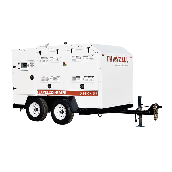
- Page 1 Part #600280 Date : Sept 2019 XHR700 Operators Manual CATERPILLAR/DEUTZ ENGINES...
-
Page 2: Ways To Contact Us
As a new customer of Thawzall we would like to welcome you! We are looking forward to providing you with technical support for your Thawzall unit. Whatever you need we are here to help. Ways to contact us for support By Phone : 1-888-757-3545 The main Technical support phone line is staffed monday-friday 7:00 AM to 3:30 PM excluding holidays. -
Page 3: Unit Information
Purchase date: ______/______/_______ Machine model:____XHR700____________________ Machine serial number:________________ *Vin number located on trailer tongue* Manufactured by Thawzall, LLC A DIVISION OF TAMARACK INDUSTRIES 2736 Latoka Lane Unit B Alexandria, MN 56308 Phone 320.759.1588 Fax: 320.759.1583 Tech Support 888.757.3545 Website:www.Thawzall.com... -
Page 4: Proposition 65 Warning
WARNING CALIFORNIA - Proposition 65 Warning Engine exhaust and some of its constituents and some dust created by power sanding, sawing, grinding, drilling and other construction activities contains chemicals known to the State of California to cause cancer, birth defects and other reproductive harm. -
Page 5: Introduction
Heater, read and understand the Safety, Operation, Maintenance and Trouble Shooting information contained in the Operator's Manual. This manual is applicable to the XHR700 built by Tamarack Industries. Use the Table of Contents as a guide when searching for specific information. -
Page 6: Table Of Contents
Table of contents Title Pages Ways to contact Us Unit Information Proposition 65 warning Introduction Safety 6-11 Warranty 12-13 How it works Controls Operating Procedures Main Screen Overview 17-22 Diagnostics Overview 23-26 Service screen overview Troubleshooting 28-32 Maintenance 33-44 Specifications MSDS 46-49 Schematics... -
Page 7: Safety
SAFETY SAFETY ALERT SYMBOL This Safety Alert symbol means The Safety Alert symbol identifies ATTENTION! BECOME ALERT! important safety messages on the YOUR SAFETY IS INVOLVED! Tamarack Heat King and in the manual. When you see this symbol, be alert to the possibility of personal injury or death. - Page 8 1. Read and understand the Operator's manual and all YOU are responsible for the SAFE operation and safety signs before maintenance of your Tamarack Industries Heat operating, maintaining, King. YOU must ensure that you and anyone else adjusting, servicing or who is going to operate, maintain or work around cleaning the Heater.
- Page 9 TIRE SAFETY 11. Hot surface ~ Avoid contact with hot exhaust and glycol system. Allow to cool before performing repairs 1. Failure to follow proper procedures when or service. mounting a tire on a wheel or rim can produce an explosion which may result in serious injury or death.
- Page 10 OPERATING SAFETY MAINTENANCE SAFETY 1. Review the Operator's Manual and all safety 1. Read and understand the Operator’s Manual items before working with, maintaining or and all safety signs before operating, servic- operating the Heater. ing, maintaining or adjusting the Heater. 2.
- Page 11 SAFE TRANSPORTATION AND STORAGE TRANSPORTING SAFETY 1. Attach to towing vehicle and secure with a me- chanical retainer. Cross the safety chains under the hitch and anchor to truck frame. 2. Connect the brake anchor cable to the truck frame to activate the trailer brakes if the trailer unexpectedly unhooks.
- Page 12 SIGN-OFF FORM Tamarack Industries follows the general Safety Standards specified by the Society of Automotive Engi- neers (SAE) and the Occupational Safety and Health Administration (OSHA). Anyone who will be operat- ing and/or maintaining the Heat King must read and clearly understand ALL Safety, Operating and Mainte- nance information presented in this manual.
-
Page 13: Warranty
TAMARACK INDUSTRIES THAWZALL WARRANTY REGISTRATION FORM & INSPECTION REPORT WARRANTY REGISTRATION (please print) This form must be filled out by the dealer and signed by both the dealer and the customer at the time of deliv- ery. Customer’s Name Distributor Name... - Page 14 Tamarack Industries CONDITIONS OF SALES & LIMITED WARRANTY All sales made by Tamarack Industries, here after ref- from contract, or the performance or breach thereof, or ered to as Tamarack, a Division of ELJO Industries Inc. the design, manufacture, sale, delivery, resale, installa-...
-
Page 15: How It Works
How It Works XHR700 : FLAMELESS HEATER HEATER COILS SLIDE GATE HEAT EXCHANGER POSITIVE AIR SHUTOFF ENGINE EXHAUST On board Diesel Fuel Tank Generator ENGINE CLEAN HOT AIR RADIATOR MUFFLER AIR TEMP SENSOR TO OUTSIDE AIR FLOW SENSOR Flameless Heater: This equipment was designed for space heating of buildings under construction, as an outdoor application with engine exhaust gases discharged outdoors. -
Page 16: Controls
Controls PART NUMBER: 600307 – PROGRAMMED HMI 1. TACTILE KEY’S 1.1. Used for screen navigation & button activation 2. TOUCHSCREEN 2.1. Displays machine graphics & parameters 2.2. Touch activation as described in Screen Operation Section 3. HMI INDICATORS 3.1. Power Indication & Mode Status 3.2. -
Page 17: Operating Procedures
OPERATIONS STARTUP PRE-MACHINE STARTUP (PRE-STARTUP INSPECTION PERFORMED) PRE-ALARM & ENGINE START SEQUENCE 1. At the Main Screen or Engine Screen press 2. Provided ECU “Wait to Start” lamp is OFF, HMI buzzer will begin to beep for 5sec indicating the Engine is about to start 3. -
Page 18: Main Screen Overview
SOFTWARE MAIN SCREEN - OVERVIEW 1. DISPLAY 1.1. Engine Battery Voltage is display here. Data is transmitted over J1939 network from Engine. 1.1.1. NOTE: No Engine data is transmitted when the Ignition is OFF. 1.2. Machine status is displayed here including Faults, Warnings, and Engine Codes. - Page 19 1.6.Engine Wait is displayed with the following icon. Data is transmitted over J1939 network from Engine. Refer to engine manufacturer for further information. Inactive - Active 1.7.Engine Stop is displayed with the following icon. Data is transmitted over J1939 network from Engine. Refer to engine manufacturer for further information. Inactive - Active 1.8.Engine Fault is displayed with the following icon.
- Page 20 1.13. Duct Temperature is displayed here in Fahrenheit. 2. NAVIGATION 2.1. Press adjacent tactile button or touch screen icon to navigate to SETUP SCREEN. 2.1.1. NOTE: This feature disappears when equipment is running. 2.2. Press adjacent tactile button or touch screen icon to navigate to MAINTENANCE SCREEN.
- Page 21 ENGINE SCREEN - OVERVIEW 1. DISPLAY (Notice display features carry over from Main Screen) 1.1. Engine Temp is displayed in the field below this icon. Data is transmitted over J1939 network from Engine. Refer to engine manufacturer for further information. 1.2.
- Page 22 SETUP SCREEN - OVERVIEW 1. DISPLAY 1.1.ENGINE TYPE is the selected engine profile to be controlled 1.1.1. CAT 3.4B 1.1.2. DEUTZ TCD2.9 1.1.3. JOHN DEERE All temperatures displayed in Fahrenheit 1.2.LOW TEMP SETPOINT is the LOW temperature setting. 1.3.MID TEMP SETPOINT is the MEDIUM temperature setting. 1.4.HIGH TEMP SETPOINT is the HIGH temperature setting.
- Page 23 1.9.HEATER 1 DELAY is the time delay after the Blower Motor is engaged for the purpose of limiting inrush current. Display is in seconds. 1.10.ELECTRIC ACTUATOR is to enable the Actuator controls when installed. 1.11.IDLE RPM is to set the engines IDLE RPM. This is for qualified personnel ONLY. 1.12.CUTOUT RPM is the RPM at which the start signal will disengage due to the engine running.
-
Page 24: Diagnostics Overview
DIAGNOSTICS SOFTWARE DIAGNOSTIC SCREEN - OVERVIEW 1. DISPLAY - Function ON/ Device Online - Function OFF/ Device Offline 1.1.OUTPUTS displays the status for a column of Digital functions being controlled 1.2.INPUTS displays the status for a column of Digital & Analog functions being monitored. - Page 25 3.1. Log Export is activated here. Machine log will upload to compatible USB storage device. 3.2. Parameters Export is activated here. Machine parameters can be downloaded to compatible USB storage device. (Factory Use) 3.3. Parameters Import is activated here. Machine parameters can be downloaded to compatible USB storage device.
- Page 26 HARDWARE CONTROL PANEL 1. Back Panel Components 1.1.DC Fuse Holders provide Blown Fuse Status 1.1.1. 1.2.DC Control relays provide ON/OFF LED indication 1.2.1. 1.3.DC Power Supply provides indication that output voltage is good (>90%) 1.3.1. 1.4.Class CC Fuse Holder provide Blown Fuse Status 1.4.1.
- Page 27 CHASSIS COMPONENTS 1. 600449R0 – Chassis Harness 1.1.E-STOP Operator provides indication of status 1.1.1. E-STOP pressed – LED ON 1.1.2. E-STOP pulled out – LED OFF 1.1.3. 2. 600318 – Air Flow Sensor 2.1.Sensor provides indication of status 2.1.1. Power/ Standby – Red 2.1.2.
-
Page 28: Service Screen Overview
SERVICE SOFTWARE SERVICE SCREEN – OVERVIEW 1. NAVIGATION 1.1. Selecting “Information, CAT engine, Deutz Engine, John Deere Engine, Fuel Filter, Oil & Filter, or Cooling System” will direct you to a PDF containing information pertaining to that subject. 1.2. Returns To Previous Screen 2. -
Page 29: Troubleshooting
TROUBLESHOOTING SOFTWARE COMMANDED SHUTDOWN FAULTS Faults that activate shutdown sequence without activating Intake Valve Shutoff 1. CODE: ‘WARNING’ ‘Fuel Level Low’ 1.1.CAUSE: Fuel Level dropped below 2%. 1.2.HOW TO CLEAR: Fuel Level must reach >10%. 2. CODE: ‘FAULT’ ‘Fuel Level Sensor’ 2.1.CAUSE: Fuel Sensor Signal not detected. - Page 30 EMERGENCY SHUTDOWN FAULTS Faults that activate immediate shutdown and activate Intake Valve Shutoff 1. CODE: ‘CYCLE POWER’ ‘E-Stop Shutdown’ 1.1.CAUSE: E-Stop operator pressed. 1.2.HOW TO CLEAR: Correct Cause & Cycle Power. 2. CODE: ‘CYCLE POWER’ ‘Gas Detect Shutdown’ 2.1.CAUSE: Gas Detect Sensor signal ON indicating atmosphere is unsafe to operate. 2.2.HOW TO CLEAR: Correct Cause &...
- Page 31 5. CODE: ‘WARNING’ ‘High Engine Temp’ 5.1.CAUSE: Engine Temp reached 210degF. This is to warn operator prior to engine ECM commanding shutdown. 5.2.HOW TO CLEAR: Correct Cause. 6. CODE: ‘WARNING’ ‘Intake Valve Closed’ 6.1.CAUSE: Intake Shutoff Valve has not reset by controller. Engine will not start. 6.2.HOW TO CLEAR: Cycle Power or wait for Intake Controller to reset valve.
- Page 32 2. ISSUE: No Power at PS1 POSSIBLE CAUSES 2.1. Engine not running at High Idle 2.1.1. Initiate Start Cycle 2.2. 15A Fuse Blown (“F5” – 600435) 2.2.1. Needs to be replaced 3. ISSUE: No Power to LM1 POSSIBLE CAUSES: 3.1.Disconnect OFF 3.1.1.
- Page 33 7. ISSUE: Engine not Online POSSIBLE CAUSES: 7.1. Ignition not ON or Start Cycle has not been initiated 7.2. Emergency condition NOT cleared 7.2.1. See Message Center on HMI and refer to Software Codes. 7.3. 25A Fuse blown (P09 – 600449R0) 7.3.1.
-
Page 34: Maintenance
Maintenance NOTE: The Thawzall XHR700 can be equipped with a CATERPILLAR or DEUTZ engine. Please refer to the appropriate service information for your engine. Top level maintenance is provided in this section. For detailed engine maintenance procedures please refer to the engine manufacturers operation and maintenance manual supplied with your heater. - Page 35 Maintenance Record DATE HOURS SERVICED BY SERVICE PERFORMED...
- Page 36 XHR700 Engine Maintenance Chart Caterpillar Engine Description Operation Every Every Monthly Hours Hours Engine oil Change Engine Oil Change filter Engine Air Check Filter Engine Fuel Change filter Grease Axle Service Hubs Torque Check Wheel Nuts (120 ft/lbs) Service Parts Description Part Number/ Type Engine Oil...
- Page 37 XHR700 Engine Maintenance Chart Deutz Engine Description Operation Every Every Monthly Hours Hours Engine oil Change Engine Oil Change filter Engine Air Check Filter Engine Fuel Change filter Grease Axle Service Hubs Torque Check Wheel Nuts (120 ft/lbs) Service Parts Description Part Number/ Type Engine Oil...
- Page 38 Air Filter NOTE: Mechanical Service indicator is only used on units with CATERPILLAR engines Mechanical Service Indicator Observe the service indicator. The air cleaner element should be replaced when one of the follow- ing conditions occur: • The yellow diaphragm enters the red zone •...
- Page 39 1. Clamp 2. Filter hood 3. Outer air filter 4. Inner air filter 5. Hexagon nut Maintaining the Air filter NOTICE Do not clean the air filter with chemicals or hot liquids! • Maintain the filter elements according to the interval in the maintenance schedule •...
- Page 40 Fuel Filter Change fuel filter Remove Remove the spin-on fuel filter with a filter wrench, collect escaping fuel. Install Do not pre-fill an on-engine fuel filter with fuel. Prefilling the fuel filter can result in debris enter- ing the fuel system and damaging fuel system components Lubricate the O-ring seal with clean lubrication oil.
- Page 41 Fuel/Water Separator DEUTZ ENGINE Priming the Fuel System 1. Fuel supply flow to the pump 2. Venting Screw NOTICE 3. Electrical connection for water level sensor. Do not crank the engine continuously for 4. Drain Plug more than 30 seconds. Allow the starting 5.
- Page 42 Fuel/Water Separator CATERPILLAR ENGINE 1. Venting Screw Priming the Fuel System 2. Drain Valve 3. Drain tube connection( if necessary) NOTICE 4. Electrical connection Do not crank the engine continuously for more than 30 seconds. Allow the starting Draining Water motor to cool for two minutes before crank- •...
- Page 43 Engine Oil and Filter Oil Drain To reduce the possibility of personnel injury, avoid direct contact of hot oil with your skin. Danger of scalding! Do not pull out the dipstick with the engine running. Danger of injury! NOTE: For most engines, use a container that can hold at least 20 liters (21qt) of lubricating oil. Change the lubricating oil and filter at the specified oil change interval.
- Page 44 Change oil filter REMOVE Clean the area around the lubricating oil filter head. Use an oil filter wrench to remove the filter. Clean the gasket surface of the filter head. NOTE: The O-ring can stick on the filter head. Be sure it is removed before installing the new filter.
- Page 45 Fill Clean and check the lubricating oil drain plug threats and sealing surface. Use a new sealing washer, if damaged. Install the lubricating oil pan plug. CATERPILLAR ENGINE DEUTZ ENGINE Fill the engine with clean lubricating oil to the proper level. Idle the engine to inspect for leaks at the drain plug and , if replaced, the oil filter seal.
-
Page 46: Specifications
XHR700 Specifications General Capacities and Component Specifications Height (w/ heater vent) 93” Width 90” Length 191” Weight ( Fuel Empty/Full) 7360/8770 LBS Engine (2 options) Caterpillar C3.4B/ Deutz TCD2.9 Air Ducts 2 x 16” Heater Element 480V Electric Trailer and Fuel Tank Axles 2- 5000 Lb. - Page 47 Material Safety Data Sheet WHMIS (Pictograms) WHMIS (Classification) Protective Clothing TDG (pictograms) B-3, D-2B Section 1. Chemical Product and Company Identification DIESEL FUEL W104 Product Name Code SAP: 120, 121, 122, 287 Validated on 3/2/2001. Diesel 50, Diesel 50 LS, #1 Diesel , #1 Diesel LS, Diesel LC, Seasonal Diesel, Synonym Seasonal Diesel LS, Diesel AA, Domestic Marine Diesel, International marine Diesel, Seasonal Diesel Locomotive, Domestic Marine diesel LS, diesel -20°C...
- Page 48 DIESEL FUEL Page Number: 2 Fire Fighting NAERG96, GUIDE 128, Flammable liquids (Non-polar/Water-immiscible). CAUTION: This product has a moderate flash point above 40ºC: Use of water spray when fighting fire may be inefficient. Media and Instructions If tank, rail car or tank truck is involved in a fire, ISOLATE for 800 meters (1/2 mile) in all directions; also consider initial evacuation for 800 meters (1/2 mile) in all directions.
- Page 49 DIESEL FUEL Page Number: 3 Vapour Pressure 1.0 kPa @ 20ºC (7.5 mmHg @ 68ºF). Dispersion Properties Not available Volatility <0.1 (Butyl acetate = 1), less than gasoline. Solubility Insoluble in cold water, soluble in non-polar hydrocarbon solvents. Section 10. Stability and Reactivity Not available Corrosivity Stability...
-
Page 50: Msds
DIESEL FUEL Page Number: 4 Section 13. Disposal Considerations Preferred waste management priorities are: (1) recycle or reprocess; (2) incineration with energy recovery; (3) disposal at Waste Disposal licensed waste disposal facility. Ensure that disposal or reprocessing is in compliance with government requirements and local disposal regulations. -
Page 51: Schematics
SCHEMATICS... - Page 52 SHEET 1 24VDC OUTPUT...
- Page 54 CAT ADAPTER HARNESS...
- Page 55 DEUTZ ADAPTER HARNESS...
- Page 56 2736 Latoka Lane SW, Unit B Alexandria,MN 56308 WWW.THAWZALL.COM support@tamarack-ind.com 1-888-757-3545 1-320-759-1583...