Table of Contents
Advertisement
Quick Links
Advertisement
Table of Contents

Related Manuals for Tamarack Industries Thawzall HEATZONE TCH250

Summary of Contents for Tamarack Industries Thawzall HEATZONE TCH250
- Page 1 Part #T90099 Date: Sept 2019 TCH250 Operators Manual...
- Page 2 As a new customer of Thawzall we would like to welcome you! We are looking for- ward to providing you with technical support for your Thawzall unit. Whatever you need we are here to help. Ways to contact us for support By Phone : 1-888-757-3545 The main Technical support phone line is staffed monday-friday 7:00 AM to 3:30 PM excluding holidays.
- Page 3 Machine model:________________________ Generator KW:__________________________________ Machine serial number:________________ Generator Serial #:_____________________________ *Serial number located on trailer tongue* Manufactured by Thawzall, LLC A DIVISION OF TAMARACK INDUSTRIES 2736 Lakota Lane Unit B Alexandria, MN 56308 Phone 320.759.1588 Fax: 320.759.1583 Tech Support 888.757.3545 Website: www.Thawzall.com...
- Page 4 WARNING CALIFORNIA - Proposition 65 Warning Engine exhaust and some of its constituents and some dust created by power sanding, sawing, grinding, drilling and other construction activities contains chemicals known to the State of California to cause cancer, birth defects and other reproductive harm.
- Page 5 Heater, read and understand the Safety, Operation, Maintenance and Trouble Shooting information contained in the Operator's Manual. This manual is applicable to the TCH250 built by Tamarack Industries. Use the Table of Contents as a guide when searching for specific information.
-
Page 6: Table Of Contents
Table of contents Title Pages Ways to contact Us Unit Information Warning Introduction Safety 6-11 Warranty 12-13 How It Works Controls 15-19 Operation 20-28 Ground Thaw Set Up 29-33 Troubleshooting 34-37 Alarms 38-40 Maintenance 41-48 Specifications MSDS 50-59 Schematics 60-65... - Page 7 SAFETY SAFETY ALERT SYMBOL This Safety Alert symbol means The Safety Alert symbol identifies ATTENTION! BECOME ALERT! important safety messages on the YOUR SAFETY IS INVOLVED! Tamarack Heat King and in the manual. When you see this symbol, be alert to the possibility of personal injury or death.
- Page 8 1. Read and understand the Operator's manual and all YOU are responsible for the SAFE operation and safety signs before maintenance of your Tamarack Industries Heat operating, maintaining, King. YOU must ensure that you and anyone else adjusting, servicing or who is going to operate, maintain or work around cleaning the Heater.
- Page 9 TIRE SAFETY 11. Hot surface ~ Avoid contact with hot exhaust and glycol system. Allow to cool before performing repairs 1. Failure to follow proper procedures when or service. mounting a tire on a wheel or rim can produce an explosion which may result in serious injury or death.
- Page 10 OPERATING SAFETY MAINTENANCE SAFETY 1. Review the Operator's Manual and all safety 1. Read and understand the Operator’s Manual items before working with, maintaining or and all safety signs before operating, servic- operating the Heater. ing, maintaining or adjusting the Heater. 2.
-
Page 11: Warning
SAFE TRANSPORTATION AND STORAGE TRANSPORTING SAFETY 1. Attach to towing vehicle and secure with a me- chanical retainer. Cross the safety chains under the hitch and anchor to truck frame. 2. Connect the brake anchor cable to the truck frame to activate the trailer brakes if the trailer unexpectedly unhooks. - Page 12 SIGN-OFF FORM Tamarack Industries follows the general Safety Standards specified by the Society of Automotive Engi- neers (SAE) and the Occupational Safety and Health Administration (OSHA). Anyone who will be operat- ing and/or maintaining the Heat King must read and clearly understand ALL Safety, Operating and Mainte- nance information presented in this manual.
-
Page 13: Safety
TAMARACK INDUSTRIES THAWZALL WARRANTY REGISTRATION FORM & INSPECTION REPORT WARRANTY REGISTRATION (please print) This form must be filled out by the dealer and signed by both the dealer and the customer at the time of deliv- ery. Customer’s Name Distributor Name... - Page 14 Tamarack Industries CONDITIONS OF SALES & LIMITED WARRANTY All sales made by Tamarack Industries, here after ref- from contract, or the performance or breach thereof, or ered to as Tamarack, a Division of ELJO Industries Inc. the design, manufacture, sale, delivery, resale, installa-...
-
Page 15: How It Works
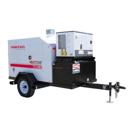
How It Works TCH 250 – DIESEL Flue exhaust Level switch Return Thermostat manifold Safety Thermostat Circulating pump On-board Diesel Tank Boiler Supply Supply Temp manifold sensor The Thawzall TCH250 is designed to heat a propylene glycol water solution which is then used for ground thawing, concrete curing or space heating. -
Page 16: Controls
Controls... - Page 17 Main Status Screen Fuel Level - Current reading of the fuel level sender located in the fuel tank Supply Temperature- Current reading of the temperature sensor located in the supply line feeding the manifold. Return Temperature- Current reading of the temperature sensors located in each of the return ports on the manifold.
- Page 18 Navigating the controller Alarm] Key - Pressing this key will display any active alarms and provide read access to historical alarm data. When the key is flashing red, an active unacknowledged alarm is present. Solid red indicates an active acknowledged alarm. [Program] Key - This key provides access to the various advanced settings of the controller.
- Page 19 Settings Screen Target Condition- Use the enter key to move the cursor to this field and use the up/down keys to change to the desired target temperature. Once completed press the enter key to save. Units of Measure- Use the enter key to move the cursor to this field and the up/down keys to toggle between units.
- Page 20 I/O Screen I/O Status- This screen shows the status of the various switches and sensors of the unit. This is stricly for information and no changes can be made on this screen. Use the up/down arrows to toggle through the different screens.
- Page 21 Pre-Start Checks & Procedures 1. Unit must be leveled for best performance in both directions: front to back, and side to side. 2. Ensure all switches on the control panel – located at the rear of the unit- are in the OFF position. 3.
- Page 22 10. If the unit starts without alarms, ensure the “Tridicator” gauge (temp+ pressure) located at the boiler, (driver side) shall display the unit operating pressure between 5 and 10 PSI . 11. If the unit displays a LOW LEVEL alarm, follow the “fill up” instructions located at the boiler when accessing the unit from the driver’s side service door, then reset the low level switch (located right above the boiler (driver side).
- Page 23 Startup Ensure the machine is sitting as level as possible. Use grounding rod if possible. 1. Make sure all switches on the control panel are in the off position. Power Source Selector Switch 2. Apply power to the machine. There are 2 methods of applying power to the ma- chine.
- Page 24 3. Once there is power to the machine, start setting up at least one hose or all 5 hoses to get circulation established. Use the power out function of the hose reel to aid in pulling the hose off of the hose reel. There are switches for the hose reel op- eration on the control panel.
- Page 25 5. Open the fuel valve on the fuel tank, turn the main power switch on the control panel to the “ON” position and this will start the pump and send power to the furnace. After a 30 second delay the furnace will attemp to light . Valve shown in open position 6.
- Page 26 Shut Down When the job is done and it is time to shut the machine down turn the main power switch to the off position and the unit will automatically go into “Cool Down” mode shown with indicator light. Doing so removes power from the furnace and allows the heat transfer fluid to continue to circulate until the furnace cools down to at least 130°...
-
Page 27: Operation
Hose Reel Operation The TCH 250 has hose reel control switches on the control panel. The hose reel can be powered both to extend or retract the hose reel selected by the reel direction switch.The reel can also be released for optional free-wheeling For manual hose deployment. - Page 28 Boiler At times the TCH250 will display a low level alarm. This is a normal occurance and is mostly due to a loss of pressure in the closed loop when setting up the unit at a new jobsite. When this happens the hydronic loop must be refilled by follow- ing these steps.
- Page 29 Electric Heater Inside the cabinet you will find a 1000 watt electric heater, this is used to keep the fuel system warm and put extra load on the generator to prevent wet stacking ( a condition caused in diesel engines when there isnt enough load and the engine doesnt get hot enough to burn off carbon deposits).
-
Page 30: Ground Thaw Set Up
GROUND THAW SETUP CHARTS TEMPERATURE: 30' F or higher/-1° C USE: LAYERS OF BLANKETS TO SINGLE (R6 insulation factor) SOIL CONDITION: Gravel or Sand (good drainage) Frost Depth 12" 24" 36" 48" 60" Hose Spacing** 24" 16" 16" 16" 16" Hours to run **Hose spacing is measured inches on center TEMPERATURE: 30°... - Page 32 GROUND THAW SETUP CHARTS, cont. TEMPERATURE: -20° F or lower/ -29° C or lower LAYERS OF BLANKETS TO USE: SOIL CONDITION: DOUBLE (R12 insulation factor) Gravel or Sand (good drainage) Frost Depth 12" 24" 36" 48" 60" Hose Spacing** 16" 16"...
- Page 33 Thaw and Cure performance in the field is affected by a wide range of factors to include soil type, Performance density of frozen ice in the soil, hose spacing, thermal rating of the covering insulating blankets, and ambient temperatures. Heat performance in interior spaces is also affected by several factors to include outside ambient temperatures, heat loss through walls and ceiling, and the volume of the space to be heated.
- Page 34 HOSE CAPACITY FILL CHART GALLONS PER FOOT HOSE SIZE (Inside dia.) 0.016 0.019 0.023 1.00 0.04 1 1/4 0.063 DISCONNECT MAINTENANCE 1. Water and dirt may get into a disconnect piece and cause it to corrode or to work improperly. It is vital that dis-connects be cleaned and lubricated at least once per season or when they get dirty.
-
Page 35: Troubleshooting
Troubleshooting The Thazall TCH250 is a self-contained glycol heating system that can be used to thaw frozen ground or maintain a work area at a constant temperature. It is a simple system that requires minimal maintenance. In the following trouble shooting section, we have listed many of the problems, causes and solutions to the problems which you may encounter. - Page 36 BECKETT BURNER GENISYS™ CONTROL Three indicator lights: Basic Features: Red reset button/lockout light Pump Prime • Green flame/recycle light • Limited Reset • Recurring lockouts without a complete heat cycle puts control in restricted (hard lockout) mode Limited Recycle • If flame is established and then lost, the control will recycle until the cumulative time trial for ignition budget is exhausted and will then go into hard lockout.
- Page 37 OPERATING STATES, cont.: Once flame is established, the igniter remains on for 10 additional seconds to ensure flame stability IGNITION CARRYOVER before shutting off The flame is sustained until the call for heat is satisfied or safety limit shuts down burner If applicable, the oil solenoid valve is de-energized and the motor continues to run for the preset MOTOR-OFF DELAY (post-time) motor-off delay time.
- Page 38 OPERATING STATES, cont.: Press and hold red reset button for 1 second at any time to disable the burner DISABLE FUNCTION When you release the reset button the burner will return to normal operation • Genisys control has limited reset •...
-
Page 39: Alarms
Alarms ALARM SCREEN In the even of a problem any active alarms will automatically be displayed. Use the [up] / [down] keys to scroll through the list of active alarms, See next page for alarms list. Alarm Code – The alarm code is a unique identifier for each alarm condition. For a complete list of possible alarm conditions see “Alarm list”... - Page 40 When an active alarm is present, the [Alarm] key will flash red. Pressing the key will take the operator to the main alarm screen: ALARM LIST Index Reset Alarm Description Alarm Action Memory Failure All functions stopped, replace PLC Memory Error All functions stopped, replace PLC AUTO Emergency Stop...
- Page 41 ALARM RESET Alarms can be reset by the operator through the alarm screen. This is done by pressing and holding the [Alarm] for 3 seconds: ALARM LOGGER The alarm logger contains a list of historical alarm events for the purpose of troubleshooting. The log- ger can be accessed through the alarm screen by pressing the [Enter] key: The records can be scrolled through using the up and down keys.
- Page 42 MAINTENANCE SAFETY 5. Always wear heavy gloves to prevent burns 1. Review the Operator's Manual and all safety when handling hot components. Wait until burn- items before working with, maintaining or ers, coils and glycol system components have operating the Heater. cooled before working on them.
- Page 43 Maintenance Chart Description Operation Every Monthly Annually Hours Burner Nozzle Change Burner Electrodes Change Burner Fuel filter Change Grease Axle Hubs Service Grease Reel Bear- Service ings Reel Gear Box Check Service Parts Item Part # Burner 1.75 80° A GPH Nozzle T10628 Fuel pump T10465...
-
Page 44: Maintenance
Burner Maintenance DO NOT TAMPER WITH THE UNIT OR CONTROLS - CALL YOUR SERVICE PERSONNEL. To ensure continued reliable operation, a qualified service technician must service this burner every 750 hours. More frequent service intervals may be required in dusty or adverse environments. Operation and adjustment of the burner requires technical training and skillful use of combustion test instruments and other test equipment. - Page 45 CHANGING FUEL NOZZLE AND ELECTRODES Annually or every 750 hours (or more often if fuel quality is poor) the fuel nozzles and elecrodes should be changed. To change, follow this procedure: Check/adjust electrodes Check the electrode tip settings. Adjust if necessary to comply with the dimensions shown. To adjust, loosen the electrode clamp screw and slide/rotate electrodes as necessary.
- Page 46 Removing Nozzle Line Assembly 1. Turn off power before servicing. 2. Disconnect oil connector tube from nozzle line. 3. Loosen the two screws securing igniter retaining clips and rotate both clips to release igniter baseplate. Then tilt igniter back on its hinge.
- Page 47 4. Remove splined nut. 5.Remove nozzle line assembly from burner, being careful not to damage the elec- trodes or insulators while handling. To ease removal of the assembly rotate assembly 180° from installed position after pulling partially out of tube. *To replace the nozzle assembly, reverse the above steps.
- Page 48 Complete Drawer Assembly Removed Nozzle and Electrodes Removed...
- Page 49 Filters Fuel Filter: The burner fuel circuit is designed with a filter to remove contaminants and water from the fuel. Change filter every 750 burner hours to keep the system clean. Change more frequently if contaminants are introduced into the system during re- fuelling.
- Page 50 TCH250 Specifications General Capacities and Component Specifications Height 90 in. Width 84 in. Length (from hitch) 172 in. Ground Clearance 12 in. Weight (w/ glycol) 5600 lbs. Weight (w/ fuel and glycol) 6580 lbs. Fuel Capacity 138 US gal. Glycol / water capacity 83 US gal 50/50 Mix Hoses 5 x 600 ft.
- Page 51 SAFETY DATA SHEET THE DOW CHEMICAL COMPANY Product name: DOWFROST™ Heat Transfer Fluid Issue Date: 04/09/2015 Print Date: 04/10/2015 THE DOW CHEMICAL COMPANY encourages and expects you to read and understand the entire (M)SDS, as there is important information throughout the document. We expect you to follow the precautions identified in this document unless your use conditions would necessitate other appropriate methods or actions.
- Page 52 Product name: DOWFROST™ Heat Transfer Fluid Issue Date: 04/09/2015 This product is a mixture. Component CASRN Concentration Propylene glycol 57-55-6 > 95.0 % Dipotassium hydrogen phosphate 7758-11-4 < 3.0 % Water 7732-18-5 < 3.0 % 4. FIRST AID MEASURES Description of first aid measures General advice: If potential for exposure exists refer to Section 8 for specific personal protective equipment.
- Page 53 Product name: DOWFROST™ Heat Transfer Fluid Issue Date: 04/09/2015 Advice for firefighters Fire Fighting Procedures: Keep people away. Isolate fire and deny unnecessary entry. Use water spray to cool fire exposed containers and fire affected zone until fire is out and danger of reignition has passed.
- Page 54 Product name: DOWFROST™ Heat Transfer Fluid Issue Date: 04/09/2015 Engineering controls: Use local exhaust ventilation, or other engineering controls to maintain airborne levels below exposure limit requirements or guidelines. If there are no applicable exposure limit requirements or guidelines, general ventilation should be sufficient for most operations. Local exhaust ventilation may be necessary for some operations.
-
Page 55: Specifications
Product name: DOWFROST™ Heat Transfer Fluid Issue Date: 04/09/2015 Vapor Pressure 2.2 mmHg Literature Relative Vapor Density (air = 1) >1.0 Literature Relative Density (water = 1) 1.05 at 20 °C (68 °F) / 20 °C Literature Water solubility 100 % Literature Partition coefficient: n- no data available octanol/water... - Page 56 Product name: DOWFROST™ Heat Transfer Fluid Issue Date: 04/09/2015 Acute dermal toxicity Prolonged skin contact is unlikely to result in absorption of harmful amounts. For the major component(s): Propylene glycol. LD50, Rabbit, > 20,000 mg/kg Acute inhalation toxicity At room temperature, exposure to vapor is minimal due to low volatility. Mist may cause irritation of upper respiratory tract (nose and throat).
- Page 57 Product name: DOWFROST™ Heat Transfer Fluid Issue Date: 04/09/2015 Based on physical properties, not likely to be an aspiration hazard. 12. ECOLOGICAL INFORMATION Ecotoxicological information on this product or its components appear in this section when such data is available. Toxicity Propylene glycol Acute toxicity to fish...
- Page 58 Product name: DOWFROST™ Heat Transfer Fluid Issue Date: 04/09/2015 Theoretical Oxygen Demand: 1.68 mg/mg Chemical Oxygen Demand: 1.53 mg/mg Biological oxygen demand (BOD) Incubation Time 69.000 % 10 d 70.000 % 20 d 86.000 % Photodegradation Atmospheric half-life: 10 Hour Method: Estimated.
- Page 59 Product name: DOWFROST™ Heat Transfer Fluid Issue Date: 04/09/2015 INTENDED CONDITION AS DESCRIBED IN MSDS SECTION: Composition Information. FOR UNUSED & UNCONTAMINATED PRODUCT, the preferred options include sending to a licensed, permitted: Recycler. Reclaimer. Incinerator or other thermal destruction device. 14.
- Page 60 Product name: DOWFROST™ Heat Transfer Fluid Issue Date: 04/09/2015 Components CASRN Propylene glycol 57-55-6 California Proposition 65 (Safe Drinking Water and Toxic Enforcement Act of 1986) This product contains no listed substances knownto the State of California to cause cancer, birth defects or other reproductive harm, at levels which would require a warning under the statute.
- Page 61 CON1 CON2 BLUE BLACK BLACK Fuel Sender BROWN +VDC BLUE ‐VDC ‐VDC Actuator ‐VDC Brown = "+" ‐VDC Blue = "N" +VDC CON3 BROWN Strobe ‐VDC Black = "Y" +VDC +VDC Brown = "C" BLACK Blue = "1" BLUE Black = "3" ‐VDC Service LED SDR‐75‐24...
- Page 62 Disp. BLACK +Vterm GREEN WHITE GREY ‐ 18 BROWN ORANGE ‐ 18 +VDC BLUE GREY ‐ 18 BLACK ‐ 14 ‐VDC GREY ‐ 18 BLACK ‐ 14 BLACK ‐14 BLACK ‐14 BLACK ‐ 18 R2_2 WHITE ‐ 18 BLACK ‐14 BLACK ‐14 R3_11 BLACK ‐...
- Page 63 LOW LEVEL CUTOFF WHITE AQUASTAT BLACK WHITE 14AWG / 3C Cable WHITE BLACK BLACK ORANGE GREEN GREEN GREEN 14AWG / 4C Cable BURNER ORANGE ORANGE BLUE GREEN IG NITER Igniter BLACK L 2 ( IG N) ORANGE MO TO R Motor BLACK L 2 ( MTR)
- Page 64 SYSTEM OFF DELAY POWER SELECTOR SWITCH WHITE‐12 Generator Power Connec╞ꡌon Hubbel Twistlock BLACK‐12 0‐BLK‐12 Connector P/N: 446312 WHITE‐12 Shore Power Connec╞ꡌon BLACK‐12 Flanged Inlet NEMA 5‐15 SYSTEM Recptacle P/N: T40765 REQUEST N‐WHT‐12 75W Power Supply ON/OFF Switch SDR‐75‐24 P/N: E700396 Switch P/N: 462125 +24 ‐24...
- Page 65 From Electrical "E1" From Electrical "E1" c.pCO "+"‐ORG‐18 "‐"‐GRY‐18 ‐ c.pCO U1‐BLK SUPPLY TEMP U2‐BLK BOILER TEMP U3‐BLK RETURN TEMP #1 U4‐BLK RETURN TEMP #2 U5‐BLK RETURN TEMP #3 U6‐BLK RETURN TEMP #4 U7‐BLK RETURN TEMP #5 U8‐BLK RETURN TEMP #6 250 Ohm U9‐BLK LOW GLYCOL LEVEL...
- Page 66 PLC Inputs and Outputs INPUTS Board Point Description Notes c.pCO Glycol Supply Temperature NTC 10K@25C c.pCO Boiler Temperature NTC 10K@25C c.pCO Return Temperature Zone 1 PT1000 c.pCO Return Temperature Zone 2 PT1000 c.pCO Return Temperature Zone 3 PT1000 c.pCO Return Temperature Zone 4 PT1000 c.pCO Return Temperature Zone 5...
- Page 67 2736 Latoka Lane SW, Unit B Alexandria,MN 56308 WWW.THAWZALL.COM support@tamarack-ind.com 1-888-757-3545 1-320-759-1583...
Need help?
Do you have a question about the Thawzall HEATZONE TCH250 and is the answer not in the manual?
Questions and answers