Table of Contents
Advertisement
Quick Links
All quality FoamPro products are ruggedly designed, accurately machined, carefully assembled, thoroughly inspected
and tested. In order to maintain the high quality of your unit, and to keep it in a ready condition, it is important to follow
the instructions on care and operation. Proper use and good preventive maintenance will lengthen the life of your unit.
ALWAYS INCLUDE THE UNIT SERIAL NUMBER IN CORRESPONDENCE.
FoamPro • 26 Southern Blvd. • Nesconset, NY 11767 USA • 800-533-9511 • FAX 816-892-3178
System 3012
Model 3012
INSTALLATION AND
OPERATION MANUAL
Unit
Serial
Number
Form 836
6/19
Advertisement
Table of Contents

Related Manuals for FoamPRO 3012


Summary of Contents for FoamPRO 3012
- Page 1 Proper use and good preventive maintenance will lengthen the life of your unit. ALWAYS INCLUDE THE UNIT SERIAL NUMBER IN CORRESPONDENCE. FoamPro • 26 Southern Blvd. • Nesconset, NY 11767 USA • 800-533-9511 • FAX 816-892-3178...
-
Page 2: Table Of Contents
WARRANTY ......................Back Cover NOTE TO SYSTEM INSTALLERS IMPORTANT: Please provide a copy of the FoamPro manual to the end user of the equipment. For additional FoamPro manuals, contact by FAX 816-892-3178, web site www.foampro.com, or call 800-533-9511. Request Form No. 836. -
Page 3: Safety
System 3012 Installation and Operation Manual Before attempting to install a FoamPro System 3012, read all Safety of the following safety precautions and follow carefully. The following special notices are used to notify and • Rotating drive line components can cause injury. Be... - Page 4 DO NOT adjust the load sense compensator. CAUTION: The cables shipped with each FoamPro 3012 are tested at the factory with that unit. Improper handling and forcing connections can damage these cables which could result in other system damage.
-
Page 5: A Quick Look At How The System Works
Display Control Module. cell configuration, inlet piping/components and system layout; please contact FoamPro at 800-533-9511 for CAUTION: If the power to the FoamPro unit fails or application-specific recommendations when foam is shut off during operation, the system will remain viscosities of 2000 cps (Brookfield #3 spindle @ 30 rpm) in operation at the last setting. - Page 6 Installation and Operation Manual Figure 2-1 FoamPro 3012 System Layout...
-
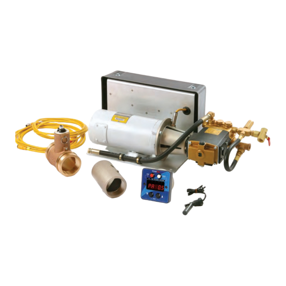
Page 7: System Component Description
(The flowmeter is a required component. The size is specified and ordered under a separate 1. Digital Display Control Module part number when the FoamPro is ordered. The 2. Molded Cables flowmeters are available with 1-1/2", 2", 2-1/2", 3", 3. Foam Pump and Hydraulic Control Valve Assembly and 4"... - Page 8 Provides capability for switching between NFPA Calibration and Test Kit for single point systems two injection points For use with 1600 thru 3012 systems Main Waterway Check Valve with Drain Port Foam Manifold Main Waterway Check Valve Available in stainless steel.
-
Page 9: Installer Supplied Parts
Hydraulic Pump Drive Selection not recommended since adequate torque usually is not available to drive the hydraulic supply pump The foam pump for the FoamPro 3012 system is powered and accessories. by hydraulics. Power for the system comes from hydraulic... - Page 10 2295 RPM Hydraulic Oil 1800 RPM 2430 RPM Ratings and data for the FoamPro 3012 system are based on operating with premium hydraulic fluids containing Oil Reservoir oxidation, rust and foam inhibitors. These premium fluids A hydraulic reservoir will be required to be installed in the include premium turbine oils, API CD engine oils per apparatus.
- Page 11 FoamPro to main water pump pressure are to be rated to 400 PSI 3012 system. The power must be supplied directly (28 Bar) or better. from the battery without any connections to other high...
-
Page 12: Installation Planning
NOTE: It is recommended that you read the following assemblies to suit the location demands. sections thoroughly before beginning installation of the FoamPro 3012. It is also recommended that you CAUTION: Never attempt to cut or lengthen the spend time planning and designing where and how molded cables. -
Page 13: Foam Pump And Hydraulic Control Valve Installation
Figure 6-1 provides the Protection must be provided for the hoses and wiring mounting dimensions for the FoamPro 3012 foam pump to prevent chafing and abrasion during operation of the and motor assemblies. -
Page 14: Hydraulic Plumbing Installation
Section 15 for required fitting sizes, minimum hose size, and minimum pressure ratings. Hydraulic Power Source The hydraulic power for the FoamPro 3012 system is The fittings required to connect the hydraulic hoses supplied by a hydraulic load-sensing pump mounted... - Page 15 FoamPro requirements for the system being installed are listed in 3012 turned off. The hydraulic pressure will be 700 PSI the table in Section 15. (48 BAR) and output flow rate will be 2 to 4 GPM (7.5 to 15.2 lpm).
-
Page 16: Water And Foam Plumbing Component Installation
The discharge relief valve on the outlet port of the potential interferences. hydraulically-driven foam pump is preset at the factory to ensure optimum performance of the FoamPro 3012 system. Hydraulic Valve Control Driver Foam Tank Power &... - Page 17 See Form 880 provided Main Waterway Flowmeters with the MultiFlo System for further information The FoamPro 3012 system is designed to accept flow reading signals from the FoamPro paddlewheel-style Injection Point flowmeter. Proper flowmeter sizing is critical to system The position of the injection point MUST be in a place accuracy.
- Page 18 Installation and Operation Manual Installation and Operation Manual water and debris in the water line to drain away from the check valve(s) as shown in Figure 8-5. This will avoid sediment deposits or formation of an ice plug in cold weather applications.
- Page 19 3. Energize FoamPro 3012 and allow electric motor Check driven foam pump to run until discharge is clear. Valve From 4. Shut off FoamPro 3012 system by depressing the Fire FOAM button on the Digital Display Control Module. Pump Close flushing water supply valve.
- Page 20 Installation and Operation Manual Outboard Pickup Switch to disconnect An outboard pickup may be adapted to the foam pump Low-Level Sensor when in Off-board inlet. The pickup should be positioned between the foam Operation Foam tank shutoff valve and the foam inlet line strainer. A tee Tank the same size as the tank to pump line, may be placed Driver...
-
Page 21: Electrical Equipment Installation
Contact the factory if molded cables of each of the electrical components. Complete molded a different length are required. cable sets are provided with each FoamPro system to make all the necessary connections. The cables • The FoamPro 3012 requires one electrical power are color coded and “indexed”... - Page 22 FoamPro Flowmeter with four #10 socket head screws in the four holes in If a single FoamPro paddlewheel-type flowmeter is to the face (see Section 15 for a mounting template). The be used, a molded cable is supplied which connects...
- Page 23 Refer to the MultiFlo Interface instructions for pipe nipple attached to the top of the tank. Ensure the installations requiring multiple FoamPro Flowmeters. pipe nipple is rigid enough to withstand the force of the Figure 9-4 shows the connection of the flowmeters and sloshing foam when the vehicle is in motion.
- Page 24 Always make sure the Control Display and the supply. The FoamPro 3012 system is not any different • – the better the power supply, the better the system will Control Driver are grounded to the chassis.
- Page 25 Engage Switch The usage of the optional solid state contactor (SSC) Open - Off is recommended to help protect the FoamPro system Closed - On from excessive voltage surges that can take place in fire apparatus systems. The SSC also has a higher life...
- Page 26 The following steps on grounding will help limit radio interference caused by the unit. In addition to adequate grounding, make sure radio cables and hardware are not located in the immediate area where the FoamPro 3012 equipment is mounted. RFI/EMI beads supplied with the FoamPro 3012 components must be mounted on the control cables and flowmeter cables.
-
Page 27: Make Sure Everything Is Working Right
System 3012 Installation and Operation Manual Make Sure Everything is Working Right Hydraulic Supply (Refer to Sections 4 & 7) · Hydraulic pump is properly mounted to the PTO. · Hydraulic oil lines are properly routed and tight. · Filter(s) are installed and tight. - Page 28 • If you are still having difficulty priming the foam pump in your FoamPro 3012 System, do the following: 1. Make sure the foam concentrate tank shutoff valve is open.
- Page 29 System 3012 Installation and Operation Manual Perform Steps 1 through 3 to wet the foam pumps to • speed the priming operation. 1. Remove one of the valve caps from the head of the foam pump; then remove the check valve under it (See Figure 10-3).
-
Page 30: Calibration And Setup
Installation and Operation Manual Calibration and Setup System Setup Procedures FoamPro systems permit easy calibration of the foam proportioning unit to assure accurate operation. The Cover Screw to calibration process will make adjustments to the be Removed flowmeter(s) and foam pump display readings. - Page 31 The total volume of foam concentrate pumped can then be When power is supplied to the FoamPro 3012 system, calculated from this weight and the density of the foam the foam concentrate injection rate in memory will be concentrate from the MSDS sheet.
- Page 32 Figure 11-2 Foam Concentrate Collection These Setup and Calibration procedures complete the adjustment of the system. The FoamPro system is now ready to be placed in service. If this system is installed and calibrated by an apparatus...
-
Page 33: Operating Instructions
The FoamPro system will monitor the water flows and control foam injection at the specified concentrate CAUTION: If the power to the FoamPro unit fails or injection rate. The system responds to variations in is shut off during operation, the system will remain water flow by increasing or decreasing the speed of the in operation at the last setting. - Page 34 Installation and Operation Manual Foam Percentage (%) If the flow decreases so the required injection rate is less than the lowest rating of the pump, the pump will When the concentrate percentage (%) is selected, run at its minimum rate and LO.FLO will flash on the buttons will respectively increase or down display to let the operator know the system is running...
- Page 35 Action Turn FoamPro system on. Display 1. Operate the apparatus engine to develop hydraulic pressure. Turn the FoamPro Main Power circuit breaker switch on. HYPRO will appear on the display momentarily. 2. Make foam solution. 2. Establish water flow to the foam capable discharge.
- Page 36 The water flow rate through the foam discharge(s) will be displayed whether foam is being pumped or not. 8. Turn the FoamPro system off. 8. Turn the apparatus Master or Battery switch off. The system can also be turned off by using the circuit breaker switch on the valve driver box.
- Page 37 System 3012 Installation and Operation Manual Simulated Flow Operation Warning: When operating the FoamPro in the The Simulated Flow function of the system allows the Simulated Flow function, an outlet for the foam operator to control the foam pump manually. The water concentrate injection must be provided.
- Page 38 Turning the apparatus Master or Battery switch off will also turn off the Simulated Flow function. The next time the power is turned on, the FoamPro will return to the original automatic default settings.
- Page 39 6. Open foam concentrate tank shutoff valve. operation. 7. Perform required maintenance checks on the 5. If the fire pump is not running, place the FoamPro FoamPro 3012. 3012 system into the simulated flow mode and proceed with above steps.
-
Page 40: Maintenance
Maintenance Maintenance Procedures 8. Bi-Annually: Drain and refill the hydraulic oil reservoir with proper hydraulic oil as noted in 1. After each use: Flush the FoamPro 3012 foam Section 4. pump (required if using other than Class A foam concentrate). -
Page 41: Troubleshooting
These diagnostic modes include: CAUTION: If the power to the FoamPro unit fails or is shut off during operation, the system will remain None in operation at the last setting. DO NOT close the... - Page 42 Installation and Operation Manual Hydraulic Valve Control Driver Foam Tank Low-Level Power & Ground Sensor Connection Pin A (Red) Foam Tank Foam Tank + 12 VDC to + 27 VDC Shutoff Valve Pin B (Black) Ground Foam Pump Assy. Speed Sensor Check Valve (Optional) Flush Water...
- Page 43 System 3012 Installation and Operation Manual Symptom Probable Cause(s) Corrective Action Pump runs for 8 to 10 seconds, Foam pump speed sensor Inspect wiring and connection then shuts down. ERR.HY may circuit open. to speed sensor. be flashed on display.
- Page 44 Low-tank level sensor or wiring Repair or replace defective is inoperative. components. Err.Su on power up. Setup parameter memory is not Contact FoamPro for replacement. functioning. NOTE: This unit will continue to operate using factory set- up values. Display shows ? for flow.
- Page 45 System 3012 Installation and Operation Manual Symptom Probable Cause(s) Corrective Action System cannot be calibrated. Calibration values selected are out Perform system reset as of range of system or setup described in Calibration Section memory is full. and recalibrate. Cannot enter Hydraulic...
-
Page 46: Specifications
Installation and Operation Manual Specifications System Capacity Foam Concentrate Rate Maximum Water Flow GPM (LPM) 0.5% 2400 (9085) 1.0% 1200 (4542) 3.0% 400 (1514) 6.0% 200 (757) System Specifications Foam Output GPM (LPM) 12 (45.4) Max. Operating Pressure PSI (BAR) 400 (28) Max. - Page 47 System 3012 Installation and Operation Manual Hydraulic Fittings and Hose Specifications System Line and Port Description Min. Hose ID Port Fitting Type & Size & Pressure Rating 3012 Hydraulic block inlet from hyd. pump 1" - 3000 psi # 8 - SAE O-Ring port Hydraulic motor outlet to cooler 3/4"...
- Page 48 Ref. Part No. Description Ref. Part No. Description 3304-0025 Calibrate/Inject Valve 1/2" NPT 3430-0351 RFI Kit for Controller 3350-0145 Strainer 1-1/2” - 3012 3430-0353 RFI Kit for Flowmeter 2527-0139 Digital Display Control 6032-0012 Instruction Placard 2520-0048 Control Cable - 6 ft.
- Page 49 System 3012 Installation and Operation Manual Parts Identification 3012 Pump Assembly Ref. Part No. Description Qty. 3304-0025 Calibrate/Inject Valve - 1/2" NPT 2404-0271 Reducer 2900-0049 Bypass Hose 2404-0272 Reducer 2402-0017 Nipple - 3/8" NPT 3300-0092 Relief Valve 2401-0033 2402-0034 Nipple - 3/4" NPT 21707 Plug - 3/4"...
- Page 50 Installation and Operation Manual Cutout Dimensions for Display Control Module Display Requires 3-7/8" [98 mm] Dia. Hole 1.04 3.50 2.70 4.25 [26.3] [88.9] [68.7] [108] 4.25 3.50 [108] [88.9] #10 24UNC x 7/16 DP (4) Holes for Mounting Cutout Dimensions for Instruction, System and System Spec. Placards...
- Page 51 System 3012 Installation and Operation Manual Parts Identification for Foam Pump/Motor Assembly Ref. Part No. Description 8000-0054 Foam Pump Assy. 9910-KIT1698 Gear Reducer 2404-0352 Adapter Shaft 2404-0351 Adapter Plate 2404-0197 Flange 3115-0039 Speed Sensor Gear 2741-0011 Coupling Half - 5/8...
- Page 52 Installation and Operation Manual FoamPro Flowmeter Sensor Assembly O-rings 4.00" min.* (102 mm Retaining Pin 85° max. NOTE #3 Female NOTES: Pipe Threads 3.12" min.* 1. Use CAUTION not to damage sensor (79 mm) during assembly. Grooved for B pipe 2.
- Page 53 System 3012 Installation and Operation Manual Load-Sensing Pump 7.16 1.61 7.16 13 Tooth, 16/32 Pitch, 30º Pressure .60 ± .02 Angle, .813 Pitch ø Fillet Root Side Fit, Compatible with ANSI B92.1 1970, Class 5 also mates with flat root side fit.
- Page 54 Installation and Operation Manual NOTES...
- Page 55 System 3012 Installation and Operation Manual NOTES...
-
Page 56: Warranty
Limited Warranty Fire Research Corp. (FRC), as supplier of FoamPro, warrants to the original purchaser, each new pump, system or other product of its own manufacture, for a period of two years from the date of shipment from the factory, to be free from defects in material and workmanship under normal use and service.
Need help?
Do you have a question about the 3012 and is the answer not in the manual?
Questions and answers