Table of Contents
Advertisement
Quick Links
This manual contains
important safety information
and must be made available to
personnel who operate and
maintain this machine.
Doosan purchased Bobcat Company from Ingersoll-Rand Company in
2007. Any reference to Ingersoll-Rand Company or use of trademarks,
service marks, logos, or other proprietary identifying marks belonging
to Ingersoll-Rand Company in this manual is historical or nominative
in nature, and is not meant to suggest a current affiliation between
Ingersoll-Rand Company and Doosan Company or the products of
either.
OPERATION AND MAINTENANCE MANUAL
SERIAL No :
C.C.N. : 22311203 en
REV
DATE
7/20
P65
Original Instruction
121001 −>
: H
: JANUARY 2010
Revised (10-12)
Advertisement
Chapters
Table of Contents

Subscribe to Our Youtube Channel
Related Manuals for Doosan Ingersoll Rand 7/20


Summary of Contents for Doosan Ingersoll Rand 7/20
- Page 1 Ingersoll-Rand Company in this manual is historical or nominative in nature, and is not meant to suggest a current affiliation between DATE : JANUARY 2010 Ingersoll-Rand Company and Doosan Company or the products of Revised (10-12) either.
- Page 2 Machine models represented in this manual may be used in various locations world−wide. Machines sold and shipped into European Union Territories require that the machine display the CE Mark and conform to various directives. In such cases, the design specification of this machine has been certified as complying with EC directives. Any modification to any part is absolutely prohibited and would result in the CE Certification and marking being rendered invalid.
- Page 4 CALIFORNIA Proposition 65 Warning Diesel engine exhaust and some of its constituents are known to the State of California to cause cancer, birth defects, and other reproductive harm.
-
Page 5: Table Of Contents
CONTENTS & ABBREVIATIONS CONTENTS ABBREVIATIONS & SYMBOLS FOREWORD #### Contact Ingersoll−Rand for serial number WARRANTY −>#### Up to Serial No. ####−> From Serial No. DECALS Not illustrated NOISE EMISSION † Option As required MAINTENANCE RECORD FOR NOISE High ambient machine EMISSION CONTROL AND EXTENDED WARRANTY F.H.R.G. -
Page 6: Foreword
© COPYRIGHT 2010 compressed air system should be: DOOSAN COMPANY of good quality, procured from a reputable manufacturer and, wherever possible, be of a type approved by Ingersoll Rand. clearly rated for a pressure at least equal to the machine maximum allowable working pressure. - Page 7 WARRANTY Ingersoll−Rand, through its distributor, warrants that each item of Ingersoll−Rand Platinum Drive Train Limited Extended equipment manufactured by it and delivered hereunder to the initial Warranty − Platinum drive train refers to the Ingersoll−Rand user will be free of defects in material and workmanship for a period of Engine and Airend combination.
- Page 8 WARRANTY GENERAL WARRANTY INFORMATION − ESA COMMENTS 12 MONTHS / 2,000 COVERS CONTROLS, SWITCHES, SHEET METAL, PORTABLE COMPRESSOR PACKAGE RADIATOR, OIL COOLER, RECEIVER, PIPEWORK, HOURS ELECTRICAL CIRCUIT ETC. 24 MONTHS / 4,000 60 MONTHS / 10,000 HOURS. EXTENDED LIMITED AIREND WARRANTY AVAILABLE ON MAJOR COMPONENTS.
-
Page 9: Warranty
WARRANTY KUBOTA 4,000 EXTENDED WARRANTY OF 60 MONTHS / 10,000 HRS. (7/20) WHEN USING GENUINE INGERSOLL−RAND FLUIDS AND PARTS ON MAJOR COMPONENTS. MITSUBISHI 2,000 NO EXTENDED WARRANTY AVAILABLE. VOLVO 2,000 EXTENDED WARRANTY PROVIDED VIA ENGINE SUPPLIER’S OWN APPROVED NETWORK AT TIME OF PURCHASE. - Page 10 WARRANTY Extended Limited Airend Warranty Ingersoll−Rand Portable Compressor Division is pleased to announce the availability of extended limited airend warranty. Announcement of the extended warranty coincides with the introduction of Pro−Tec Compressor Fluid. Pro−Tec Compressor Fluid is an amber coloured fluid specially formulated for Portable Compressors and is being provided as the factory filled fluid for all machines except XHP650/900/1070 All machines have the standard airend warranty, −...
- Page 11 To initiate the machine warranty, fill out the ”Warranty Registration” form 83242 11/99 supplied as part of the machine documentation, keep a copy for your records and mail the original to: Doosan Warranty Team Doosan Trading Limited Block B, Swords Business Campus...
- Page 12 Machines shipped outside the United States require notification be made to initiate the machine warranty. Fill out the Warranty Registration Form in this section, keep a copy for your records and mail form to: Doosan International USA, Inc 1293 Glenway Drive Statesville North Carolina 28625−9218...
- Page 13 WARRANTY PORTABLE POWER EXTENDED WARRANTY REGISTRATION FORM Customer Details Service Provider Details Company Name : Service Provider / Distributor : Contact Name : Branch Office : Signature : Machine Details Company Address : Product Type : Model : Serial Number : SAMPLE Engine Serial Number : Engine Model Number :...
- Page 14 DECALS GRAPHIC FORM AND MEANING OF ISO SYMBOLS Prohibition / Mandatory Information / Instructions Warning WARNING: Electrical shock risk. WARNING − Pressurised component or WARNING − Hot surface. system. WARNING − Pressure control. WARNING − Corrosion risk. WARNING − Air/gas flow or Air discharge. WARNING −...
-
Page 15: Decals
DECALS WARNING − Do not undertake any WARNING − Consult the operation and maintenance on this machine until the Do not breathe the compressed air from this maintenance manual before commencing electrical supply is disconnected and the air machine. any maintenance. pressure is totally relieved. - Page 16 DECALS Lifting point. On (power). Off (power). Read the Operation and Maintenance manual When parking use prop stand, handbrake and Compressor oil filling before operation or maintenance of this wheel chocks. machine is undertaken. Diesel fuel Rough Service Designation. Parking brake. No open flame.
- Page 17 DECALS Look for these signs on machines shipped to markets in North America, which point out potential hazards to the safety of you and others. Read and understand thoroughly. Heed warnings and follow instructions. If you do not understand, inform your supervisor. DANGER CAUTION Red background...
- Page 18 DECALS WARNING WARNING Improper operation of this equipment. Trapped pressure. CAN cause serious injury or death. Can cause serious injury or death. Read Operator’s Manual supplied with this machine before operation or servicing. Close service valve and operate tool to vent trapped Modification or alteration of this machine.
- Page 19 Decal part numbers are on the bottom of each decal and are also listed in the compressor’s parts manual. Submit orders for Safety Decals to the Doosan Portable Power EMEA Aftermarket Department. The no charge order should contain only Safety Decals. Help promote product safety! Assure that decals are present on the machines.
- Page 20 NOISE EMISSION This section pertains only to machines distributed within the United States. WARNING TAMPERING WITH NOISE CONTROL SYSTEM PROHIBITED Federal law prohibits the following acts or the causing thereof: (1) The removal or rendering inoperative by any persons, other than for purposes of maintenance, repair, or replacement, of any device or element of design incorporated into any new compressor for the purpose of noise control prior to its sale or delivery to the ultimate purchaser or while it is in use;...
- Page 21 NOISE EMISSION NOISE EMISSION CONTROL MAINTENANCE LOG COMPRESSOR MODEL SERIAL NO. USER UNIT NO. UNIT IDENTIFICATION DEALER OR DISTRIBUTOR FROM WHOM PURCHASED: ENGINE MAKE & MODEL: SERIAL NO.: PURCHASER OR OWNER: ADDRESS: DATE PURCHASED: The Noise Control Act of 1972 (86 Stat. 1234) prohibits tampering with the noise control system of any compressor manufactured and sold under the above regulations, specifically the following acts or the causing thereof: (1) The removal or rendering inoperative by any persons, other than for purposes of maintenance, repair, or replacement, of any device or element of design incorporated into any new compressor for the purpose of noise control prior to its sale or delivery to the ultimate purchaser or while it is in use;...
-
Page 22: Noise Emission
NOISE EMISSION INTRODUCTION The unit for which this Maintenance Log is provided conforms to U.S. E.P.A. Regulations for Noise Emissions, applicable to Portable Air Compressors. The purpose of this book is to provide (1) the Maintenance Performance Schedule below for all required noise emission controls and (2) space so that the purchaser or owner can record what maintenance was done, by whom, where and when. - Page 23 NOISE EMISSION A. COMPRESSED AIR LEAKS F. AIR INTAKE AND ENGINE EXHAUST Correct all compressed air leaks during the first shutdown period Engine and compressor air intake and engine exhaust systems after discovery. If severe enough to cause serious noise problems and should be inspected after each 100 hours of operation for loose, efficiency loss, shut down immediately and correct the leak(s).
-
Page 24: Maintenance Record For Noise Emission Control And Extended
MAINTENANCE RECORD FOR NOISE EMISSION CONTROL AND EXTENDED WARRANTY MAINTENANCE RECORD FOR NOISE EMISSION CONTROL AND EXTENDED WARRANTY ITEM NO. DESCRIPTION OF WORK OR HOURMETER MAINT/INSPECT LOCATION WORK DONE BY COMMENTS READING DATE CITY/STATE (NAME) 7/20, P65... -
Page 25: Safety
SAFETY WARNINGS WARNING: Under no circumstances should volatile liquids such Warnings call attention to instructions which must be followed as Ether be used for starting this machine. precisely to avoid injury or death. CAUTIONS Cautions call attention to instructions which must be followed precisely to avoid damaging the product, process or its surroundings. - Page 26 SAFETY Disconnected air hoses whip and can cause serious injury or death. DO NOT ATTEMPT TO SLAVE START A FROZEN BATTERY Always attach a safety flow restrictor to each hose at the source of SINCE THIS MAY CAUSE IT TO EXPLODE. supply or branch line in accordance with OSHA Regulation 29CFR Section 1926.302(b).
- Page 27 SAFETY When parking always use the handbrake and, if necessary, suitable Where brakes and safety chains are fitted: wheel chocks. a) Loop the chains onto the towing vehicle using the towing vehicle Make sure wheels, tyres and tow bar connectors are in safe hitch as an anchorage point, or any other point of similar strength.
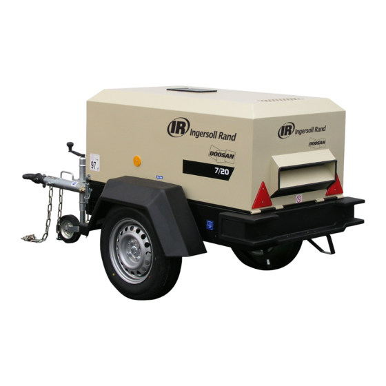
- Page 28 GENERAL INFORMATION 7/20 VARIABLE HEIGHT RUNNING GEAR 7/20 FIXED HEIGHT RUNNING GEAR 7/20, P65...
-
Page 29: General Information
GENERAL INFORMATION COMPRESSOR 7/20 INFORMATION ON AIRBORNE NOISE (‘W’ model) −1 Actual free air delivery. 1,84 m (65 CFM) − The A−weighted emission sound pressure level Normal operating discharge pressure. 7 bar (100 PSI) 84 dB(A), uncertainty 1 dB(A) Maximum allowable pressure. 8,6 bar (125 PSI) −... - Page 30 OPERATING INSTRUCTIONS COMMISSIONING Ensure that the correct fork lift truck slots or marked lifting / tie down points are used whenever the machine is lifted or transported. Upon receipt of the unit, and prior to putting it into service, it is important to adhere strictly to the instructions given below in PRIOR TO STARTING.
-
Page 31: Operating Instructions
OPERATING INSTRUCTIONS PRIOR TO STARTING CAUTION: When refueling:− switch off the engine. A. Place the unit in a position that is as level as possible. The design do not smoke. of the unit permits a 15 degree lengthways and sideways limit on out extinguish all naked lights. -
Page 32: Emergency Stopping
OPERATING INSTRUCTIONS STARTING THE MACHINE NOTE: As soon as the engine stops, the automatic blowdown valve will relieve all pressure from the system. WARNING: Under no circumstances should volatile liquids such as Ether be used for starting this machine. If the automatic blowdown valve fails to operate, then pressure must be relieved from the system by means of the service valve(s). -
Page 33: Decommissioning Lt
OPERATING INSTRUCTIONS DECOMMISSIONING When the machine is to be permanently decommissioned or dismantled, it is important to ensure that all hazard risks are either eliminated or notified to the recipient of the machine. In particular:− Do not destroy batteries or components containing asbestos without containing the materials safely. - Page 34 MAINTENANCE MAINTENANCE SCHEDULE Initial. Hours Monthly / Hours Hours Daily Weekly (miles) 200/400 1/− 3/250 6/500 12/1,000 (500) Compressor Oil Level Engine Oil Level *Radiator Coolant Level Gauges/Lamps *Air Cleaner Service Indicators Fuel Tank (Fill at end of day) *Fuel/Water Separator Drain Oil Leaks Fuel Leaks Drain Water From Fuel Filters...
-
Page 35: Maintenance Mt
MAINTENANCE Initial. Hours Monthly / Hours Hours Daily Weekly (miles) 200/400 1/− 3/250 6/500 12/1,000 (500) *Fuel/Water Separator Element Compressor Oil Filter Element Compressor Oil R/− Engine Oil Change R/− Engine Oil Filter *Water Pump Grease. *Wheels (Bearings, Seals, etc.) *Engine Coolant Fuel Filter Element −/R... - Page 36 MAINTENANCE Initial. Hours Monthly / Hours Hours Daily Weekly (miles) 200/400 1/− 3/250 6/500 12/1,000 (500) Scavenge line Pressure system Engine breather element Pressure gauge Pressure regulator Separator tank (2) exterior Lubricator (Fill) 4 Yrs 6 Yrs 2,000 Hours/ 2 Years. 2 Yrs Airend drive belt.
-
Page 37: Routine Maintenance
MAINTENANCE ROUTINE MAINTENANCE loose clothing, jewelry, long hair etc. is made safe. This section refers to the various components which require periodic maintenance and replacement. warning signs indicating that Maintenance Work is in Progress are posted in a position that can be clearly seen. The SERVICE/MAINTENANCE CHART indicates the various components’... - Page 38 MAINTENANCE SCAVENGE LINE If, however, the element has to be replaced, then proceed as follows: The scavenge line runs from the combined orifice/drop tube in the separator tank, to the orifice fitting located in the airend. Removal Examine the orifice, check valve and hoses at every service or in the event of oil carryover into the discharge air.
- Page 39 MAINTENANCE COMPRESSOR OIL COOLER AND ENGINE RADIATOR COOLING FAN DRIVE When grease, oil and dirt accumulate on the exterior surfaces of the oil Periodically check that the fan mounting bolts in the fan hub have cooler and radiator, the efficiency is impaired. It is recommended that not loosened.
- Page 40 MAINTENANCE TYRES/TYRE PRESSURE The brake actuators must not be pre−tensioned − if necessary loosen the brake linkage [7] on the brake equalisation assembly [8]. See the GENERAL INFORMATION section of this manual. Check that brake actuators and cables [11] operate smoothly. RUNNING GEAR/WHEELS Check the wheel nut torque 20 miles (30 kilometres) after refitting the wheels.
-
Page 41: Lubrication
MAINTENANCE 3: Compensator assembly adjustment Re−adjustment Variable Height models The handbrake lever [1] should be engaged forcefully several times to set the braking system. Fit an M10 safety screw to the handbrake pivot. Check the setting of the brake equalisation assembly [8], which should be at right angles to the pulling direction. - Page 42 MAINTENANCE Completely drain the receiver/separator system including the piping COMPRESSOR OIL FILTER ELEMENT and oil cooler by removing the drain plug(s) and collecting the used oil Refer to the SERVICE / MAINTENANCE CHART in this section for in a suitable container. service intervals.
- Page 43 MAINTENANCE DRIVE BELT REPLACEMENT / ADJUSTMENT. WARNING: DURING THE ADJUSTMENT / REPLACEMENT PROCEDURE ALWAYS DISCONNECT BATTERY. Remove drive belt guard. Loosen securing screw M12 beside and above the Airend. Loosen main pivot bolt M16. Disconnect adjusting screw and pivot Airend towards engine to slacken belt and remove belt from pulleys.
- Page 44 MAINTENANCE TORQUE VALUES ft lbf ft lbf Engine mounts to engine 29−35 39−47 Lifting bail to frame 29−35 39−47 Airend to pivot plate 29−35 39−47 Band clamp on oil pipes 71−88 96−119 Air filter to bracket 16−20 22−27 Radiator/Cooler to baffle 9−11 12−15 Autella clamp to exhaust...
-
Page 45: Compressor Lubrication
MAINTENANCE COMPRESSOR LUBRICATION RATED OPERATING PRESSURE Portable Compressor Fluid Chart 350 PSI 100 − 300 PSI 500 PSI 125_F 50_C Refer to these charts for correct compressor fluid required. Note that the selection of fluid is dependent on the design operating 40_C 104_F pressure of the machine and the ambient temperature expected to... - Page 46 ELECTRICAL SYSTEM Battery 12V Control fuse D1−2 Diode, blocking Fuel pump Alternator Glowplugs Hourmeter Starter motor NP1−4 Node point Engine oil pressure switch Relay, temperature switch Key−switch Solenoid, fuel High air temperature switch (airend) High water temperature switch (engine) 7/20, P65...
-
Page 47: Electrical System
ELECTRICAL SYSTEM SCHEMATIC DIAGRAM FOR EUROPEAN CE LIGHTING SYSTEM Plug Black Light (right hand) Green Fog light Pink Light (left hand) Brown Orange Purple Grey Blue White Yellow 7/20, P65... - Page 48 ELECTRICAL SYSTEM SCHEMATIC DIAGRAM FOR AMERICAN SAE LIGHTING SYSTEM Stop / turn (left hand) Black Tail (left hand) Green Stop / turn (right hand) Pink Tail (right hand) Brown Front side marker (left hand) Orange Front side marker (right hand) Purple Ground / earth Grey...
- Page 49 PIPING AND INSTRUMENTATION SYSTEM Air/oil Air discharge Compressor Sonic orifice (restricts flow) Engine Pressure gauge Oil cooler Separator tank Oil filter Safety valve 7/20, P65...
-
Page 50: Fault Finding
FAULT FINDING FAULT CAUSE REMEDY FAULT CAUSE REMEDY Engine fails Low battery Check the fan belt tension, battery Engine Incorrect Check the throttle setting. to start. charge. and cable connections. speed too throttle arm low. setting. Bad earth Check the earth cables, clean as connection. - Page 51 FAULT FINDING FAULT CAUSE REMEDY FAULT CAUSE REMEDY Excessive oil Blocked Check the scavenge line, drop tube Oil is forced Incorrect Always employ correct present in scavenge line. and orifice. Clean and replace. back into the stopping stopping procedure. Close the air filter.
-
Page 52: Options
OPTIONS LUBRICATOR FAULT FINDING SAFETY FAULT CAUSE REMEDY WARNING: Ensure that the lubricator filler cap is re−tightened correctly after replenishing with oil. No oil flow. Incorrect Reverse nylon tube connection. connections to the lubricator. WARNING: Do not replenish the lubricator oil, or service the lubricator without first making sure that the machine is stopped and the system has been completely relieved of all air pressure (Refer... - Page 53 ENGINE INSTRUCTION MANUAL KUBOTA D1005 − ENGINE CONTENTS FOREWORD EXTERNAL VIEW GENERAL INFORMATION Main data and specifications Engine identification Ingersoll Rand engine after sales support EMISSION CONTROL LABEL FUEL, LUBRICANT, AND COOLANT Fuel Lubricant Coolant OPERATION Check before operation Check and operation after start− up Operation and care of a new engine MAINTENANCE SCHEDULE PERIODICAL INSPECTION...
-
Page 54: Foreword
FOREWORD The INGERSOLL RAND industrial diesel engines are a product of long years of experience, advanced technology, and up−to date production facilities. INGERSOLL RAND takes great pride in the superior durability and operating economy of these engines. In order to get the fullest use and benefit from your engine, it is important that you operate and maintain it correctly. This Manual is designed to help you do this. -
Page 55: External View
EXTERNAL VIEWS DIESEL ENGINE Engine External View − Model 1. Intake manifold 2. Speed control lever 3. Engine stop lever 4. Injection pump 5. Fuel feed pump 6. Cooling fan 7. Fan drive pulley 8. Oil filter cartridge 9. Water drain cock 10. -
Page 56: General Information
GENERAL INFORMATION EPA CERTIFIED ENGINE DATA and SPECIFICATIONS Model: 7/20 − KUBOTA D1005−EBB−EC−LT−1 P65 − KUBOTA D1005−E3B−IRCZ Engine model name D1005−EBB−EC−L T−1 / D1005−E3B−IRCZ Engine type Vertical inline water cooled diesel engine Combustion type Spherical type (E−TVCS) No. of cylinders − bore x stroke. mm 3−76x73.6 Engine displacement cm 1,001... -
Page 57: Emission Control Label
EMISSION CONTROL LABEL EC EMISSION CONTROL LABEL: ENGINE LABEL Emission control label is attached on the “top of the rocker arm cover” The following is the detail of a label required for engine emission control information, along with location. (97/68/EC Directive label) A. -
Page 58: Fuel, Lubricant, And Coolant
FUEL, LUBRICANTS, AND COOLANT If refueling is done from an oil drum directly, ensure that it has been FUEL kept stationary to allow any dust, sediment or water to settle at the bottom. Do not draw fuel direct from the bottom of the drum to prevent Fuel Selection pickup of any settled foreign material. -
Page 59: Lubricant
FUEL, LUBRICANTS, AND COOLANT NOTE LUBRICANT Using a mixture of different brands or quality of oils will adversely affect The quality of engine oil can affect engine performance, startability the original oil quality; therefore, never mix different brand or different and engine life. - Page 60 OPERATION ENGINE OPERATION When the belt is depressed 7 − 9 mm with the thumb (about 100 N [10 kg] pressure) midway between the bottom pulley and alternator Engine Exhaust Gas Caution (Carbon Monoxide) pulley, the belt tension is correct. CAUTION If the belt tension is too high, it will result in alternator failure.
-
Page 61: Operation
OPERATION Fuel level Battery Cable Connection Check the remaining fuel oil level in the fuel tank and re−fuel if Check the battery cable connections for looseness or corrosion. A necessary. loosened cable connection will result in hard engine starting or insufficient battery charge. -
Page 62: Check And Operation After Start− Up
OPERATION S Close the service valve to reduce the load. CHECKS AND OPERATION AFTER START−UP S Let the engine run at normal idle speed for two or three minutes. If Check after the Engine Start−up the engine coolant temperature does not start to drop, turn off the Check the following items in the engine warming−up operation. - Page 63 OPERATION LONG TERM STORAGE If the equipment is to be out of operation for an extended period, it should be started at least once per week and run on load for about 15 minutes after it has reached normal operating temperature. If this is not possible, S Do not drain the cooling water S Clean dust or oil from the engine extension...
-
Page 64: Maintenance Schedule
ENGINE MAINTENANCE SCHEDULE When performing the following items, the daily inspection items should also be carried out. IMPORTANT: Establish a periodic check plan according to the operating conditions and make sure to conduct checks at specified intervals. Otherwise, malfunctioning may occur to shorten the engine life. As special knowledge and skill are required for items marked with F, consult your local Ingersoll Rand branch or distributor. - Page 65 ENGINE MAINTENANCE SCHEDULE Note: L This is a recommended maintenance. The failure to perform this maintenance item will not nullify the emission warranty or limit recall liability prior to the completion engine useful life. Ingersoll Rand, however, urges that recommended maintenance service is performed at the indicated intervals. EXPLANATION OF MAINTENANCE SCHEDULE The following is a brief explanation of the services listed in the preceding Engine Maintenance schedule.
- Page 66 PERIODICAL INSPECTION AND MAINTENANCE Inspection after initial 50 hours operation (1) Replacing the engine oil and engine oil filter (1st time) When the engine oil is still hot, be careful with a splash of engine oil which may cause burns. Cool the engine to replace engine oil until the engine oil becomes warm.
-
Page 67: Periodical Inspection And Maintenance
PERIODICAL INSPECTION AND MAINTENANCE (2) Checking and adjusting cooling fan V−belt When there is not enough tension in the V−belt, the V−belt will slip making it impossible for the alternator to generate power and cooling water pump and cooling fan will not work causing the engine to overheat. - Page 68 PERIODICAL INSPECTION AND MAINTENANCE Inspection every 50 hours operation S If the engine cranking speed is so slow that the engine does not start up, recharge the battery. S If the engine still will not start after charging, replace the battery. (1) Inspection of battery S Remove the battery from the battery mounting of the machine unit Fire due to electric short−circuit...
- Page 69 PERIODICAL INSPECTION AND MAINTENANCE (4) Checking and cleaning radiator fins. Beware of dirt from air blowing Wear−protective equipment such as goggles to protect your eyes when blowing compressed air. Dust or flying debris can hurt eyes. Dirt and dust adhering on the radiator fins reduce the cooling performance, causing overheating.
-
Page 70: Air Intake System
PERIODICAL INSPECTION AND MAINTENANCE (6) Air cleaner element inspection (1) Checking and adjusting cooling fan V−belt (2nd time and after) Check and adjust the cooling fan V−belt tension every 200 hours operation from 2nd time and on. AIR INTAKE SYSTEM Air cleaner Inspection every 400 hours operation Engine performance and life vary with the air intake conditions. - Page 71 PERIODICAL INSPECTION AND MAINTENANCE (2) Checking and adjusting the fuel injection valve As the adjustment requires specialized knowledge and skill, .consult your Ingersoll Rand dealer. This adjustment is needed to obtain the optimum injection pattern for full engine performance. (3) Adjusting intake / exhaust valve clearance As this adjustment requires specialized knowledge and skill, consult your Ingersoll Rand dealer.
-
Page 72: Troubleshooting
ENGINE TROUBLESHOOTING This item contains a simple troubleshooting. When a failure takes place on your Ingersoll Rand engine, diagnose the cause referring this troubleshooting. Should the cause of failure not be detected or you are unable to manage the failure, consult your machine supply source or nearest Ingersoll Rand engine service outlet. - Page 73 ENGINE TROUBLESHOOTING Unstable engine running Crack in injection pipe. Injection nozzle failure. Unstable low idling Engine stop solenoid return failure. Uneven compression pressure between cylinders. Incorrect high idle speed Incorrect control lever adjustment. adjustment. Governor internal malfunction. Engine hunting in medium speed Governor spring deteriorated.
- Page 74 ENGINE TROUBLESHOOTING Low engine output Incorrect injection timing Too far advanced. Too far retarded. Injection nozzle malfunction Incorrect injection pressure. Incorrect spray condition. Incorrect injection pump adjustment Lack of fuel in tank. Insufficient fuel supply to the Air in injection pump. injection pump Fuel filter clogged.
- Page 75 ENGINE TROUBLESHOOTING Improper exhaust Clogged air cleaner. Damaged injector nozzle. Excessive black smoke Wrong injector nozzle. Injection timing incorrect. Excessive injection volume. Incorrect fuel. Water mixing in fuel Excessive white smoke Low compression pressure. Injection timing incorrect. Low coolant temperature Faulty turbocharger Battery over discharge Low electrolyte level...
Need help?
Do you have a question about the Ingersoll Rand 7/20 and is the answer not in the manual?
Questions and answers