Table of Contents

Subscribe to Our Youtube Channel
Related Manuals for Dynapac F1200C


Summary of Contents for Dynapac F1200C
- Page 1 OPERATION & MAINTENANCE Paver Finisher Dynapac F1200C / F1200CS Typ 456 / 457 02-0416 4812023636 (A5) Keep for later use in document compartment Valid for: _________________ - _________________ _________________ - _________________...
- Page 2 www.dynapac.com...
-
Page 3: Table Of Contents
Performance data F1200C ............... 12 Performance data F1200CS ..............12 Travel drive/traction unit ................13 Engine EU 3A / Tier 3 - F1200C (o) ............13 Engine EU 3B / Tier 4f - F1200C (t) ............13 5.10 Engine EU 3A / Tier 3 - F1200CS (o) ............13 5.11... - Page 4 5.16 Permissible temperature ranges ..............14 Identification points ...................15 Warning signs ...................18 Information signs ..................20 CE marking ....................22 Instructive symbols, prohibitive symbols, warning symbols .....23 Further warnings and operating instructions ..........23 Identification label for the paver finisher (41) ........24 Explanation of 17PIN serial number ............25 EN standards ....................26 Continuous sound pressure level .............26 Operating conditions during measurement ..........26...
- Page 5 Output of numerical code ..............57 Fault codes ....................58 D30.12 Operation ................1 Control elements on the paver finisher ............1 Control elements on the operator's control station ........1 Control platform ..................2 Running board extension (o) ..............3 Fuse box ....................
- Page 6 Preparation for transportation ..............14 Driving and stopping the paver finisher ..........16 Preparations for paving ................17 Separator fluid ..................17 Screed heater ..................17 Direction marks ..................18 Loading/material transfer ..............20 Filling function ..................20 Starting for paving ..................22 Checks during paving ................23 Paver function ..................23 Quality of the layer ................23 Interrupting/terminating operation ............25 During breaks (e.g.
- Page 7 F3.12 Maintenance - conveyor ............1 Maintenance - conveyor ................1 Maintenance intervals ................3 Points of maintenance ................4 Chain tension, conveyor (1) ..............4 Replace conveyor / conveyor drive - wear parts (2) ......6 F4.12 Maintenance - auger assembly ..........1 Maintenance - auger assembly ..............
- Page 8 F7.12 Maintenance - drive unit ............1 Maintenance - drive unit ................1 Maintenance intervals ................3 Maintenance points ..................6 Chain tension (1) ..................6 Checking / adjusting chain tension - grease tensioner version ....6 Checking / adjusting chain tension - spring loaded tensioner version ...8 Pre-tension of the tension unit.
- Page 9 F100 Tests, stopping ..............1 Tests, checks, cleaning, stopping .............. 1 Maintenance intervals ................2 General visual inspection ................3 Check that the bolts and nuts fit firmly ............3 Inspection by an expert ................3 Cleaning ..................... 4 Cleaning the hopper ...................
-
Page 11: Preface
In the interest of continued development, the manufacturer reserves the right to make changes to the vehicle (which will not, however, change the essential features of the type of vehicle described) without updating the present operating instructions at the same time. Dynapac GmbH Wardenburg Ammerländer Strasse 93 D-26203 Wardenburg / Germany... -
Page 12: General Safety Instructions
Failure to observe this information, prohibitions and instructions can result in life- threatening injuries! The "Guidelines for the Correct Use and Application of Paver Finishers" compiled by Dynapac must also be observed! -
Page 13: Safety Signs, Signal Words
Safety signs, signal words In the safety instructions, the signal words "Danger", "Warning", "Caution", "Note" are positioned in the coloured title block. They follow a certain hierarchy; in combination with the warning symbol, they indicate the severity of the danger or the type of note. "Danger"! DANGER Danger of personal injury. -
Page 14: Warnings
Warnings Warning on a dangerous area or hazard! Failure to observe the warnings can result in life-threatening inju- ries! Warning on danger of being pulled in! In this working area/on this element there is a danger of being pulled in by rotating or conveying elements! Only carry out activities with elements switched off! Warning on dangerous electrical voltage! All maintenance and repair work on the screed's electrical system... - Page 15 Warning on danger of falling! Warning on dangers posed by batteries! Warning on hazardous or irritating substances! Warning on substances which constitute a fire hazard! Warning on gas bottles!
-
Page 16: Prohibitive Symbols
Maintenance and repair work may only be carried out with the diesel engine shut down! Spraying with water is prohibited! Extinguishing with water is prohibited! Unauthorised maintenance is prohibited! Only qualified experts may conduct maintenance! Consult the Dynapac Service Department Fire!, naked flames and smoking are prohibited! Do not switch! -
Page 17: Protective Equipment
Protective equipment Locally applicable regulations may require the wearing of various safety equipment! Always observe these regulations! Wear safety goggles to protect your eyes! Wear suitable head protection! Wear suitable hearing protection to protect your hearing! Wear suitable safety gloves to protect your hands! Wear safety shoes to protect your feet! Always wear close-fitting work clothing! Wear a warning vest to be seen in time to avoid accidents! -
Page 18: Environmental Protection
Environmental protection The locally applicable laws, guidelines and accident prevention regulations for the proper recycling and disposal of waste must always be observed, even if these are not expressly named here. Water-endangering substances like: - Lubricants (oil, grease) - Hydraulic oil - Diesel fuel - Coolant - Cleaning liquids... -
Page 19: Additional Information
Additional information Also observe the manufacturer's documentation and additional doc- umentation! For example, the maintenance instructions of the engine manufac- turer Description / depiction applicable when equipped with gas heater! Description / depiction applicable when equipped with electric heat- t Used to indicate standard equipment. o Used to indicate optional equipment. -
Page 20: Ce Identification And Declaration Of Conformity
- damage occurrs through malfunctions caused by improper use and incorrect oper- ation. - repairs or manipulations are carried out by persons who are neither trained nor au- thorised accordingly. - accessories or spare parts are used that cause damage and which are not ap- proved by Dynapac. V 10... -
Page 21: Residual Risks
Residual risks These are risks that remain even if all possible measures and safety precautions have been taken to help minimise dangers (risks) or to reduce their probability and scope to zero. Residual risks in the form of - Danger to life and limb of persons at the machine - Danger to the environment posed by the machine - Damage to property and restricted output and functionality of the machine - Damage to property in the operating range of the machine... -
Page 22: Sensibly Predictable Incorrect Usage
Sensibly predictable incorrect usage Every kind of sensibly predictable incorrect usage of the machine constitutes misuse. Incorrect usage makes the manufacturer's warranty null and void: the operator bears sole responsibility. Sensibly predictable incorrect usage of the machine includes: - presence in the danger zone of the machine - transporting persons - leaving the operator's platform while the machine is operating - removing protection or safety devices... -
Page 23: A Correct Use And Application
A Correct use and application The "Guidelines for the Correct Use and Application of Paver Finishers" compiled by Dynapac are included in the scope of delivery for the present machine. The guidelines are part of the present operating instructions and must always be heeded. -
Page 25: B Vehicle Description
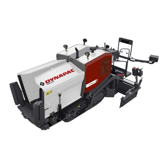
B Vehicle description Application The Dynapac F1200C/CS paver finisher is a paver finisher with a caterpillar drive which is used for laying bituminous mixed material, roll-down or lean-mixed concrete and unbound mineral aggregates for foundations for paving. -
Page 26: Description Of Assemblies And Functions
Description of assemblies and functions Item Designation Material compartment (hopper) Truck push rollers Tube for sensor rod (direction indicator) holder Caterpillar drive Levelling cylinder for paving thickness Paving thickness indicator Crossbeam Travel drive of the caterpillar drive Conveyor Auger Screed Operator’s platform Operating panel Working lights... -
Page 27: Vehicle
Vehicle Construction The paver finisher has a welded steel frame on which the individual components are mounted. The caterpillar drives are part of the frame structure; the suspension of the attached screed additionally helps to attain high paving precision. The continuously adjustable hydrostatic travel drive allows the speed of the paver fin- isher to be matched to all work conditions. - Page 28 Hydraulic system: The diesel engine drives the hydraulic pumps for all main paver finisher drives via the attached distribution gear and its auxiliary drive shafts. Travel drive: The continuously adjustable travel drive pumps are connected to the travel drive engines by means of high pressure hydraulic hoses. These hydraulic motors drive the caterpillar chains via planetary gears that are mounted directly inside the drive units of the caterpillar chains.
- Page 29 Levelling/slope control system: The standard paver finisher is prepared electrically and hydraulically to fit an automatic levelling system. The levelling system monitors the paving thickness and corrects any deviations from the nominal level automatically. The system consists of optional combinations of: - Height controllers - Slope controller - Digital controllers...
-
Page 30: Danger Zones
Danger zones WARNING Danger for persons in the danger zone Persons in the danger zone can suffer severe or fatal inju- ries from movements and functions of the vehicle! - Never stand in the danger zone of the vehicle! - During operation, only the vehicle operator and the screed personnel are allowed on the vehicle or in the danger zone. -
Page 31: Safety Devices
Safety devices 5 6 7 8... - Page 32 Item Designation Hopper transport safeguard Screed transport safeguard Main switch Travel drive safety switch Emergency stop button Horn Ignition key Lights Screed warning light Covers, lateral flaps, coverings Located on both sides of the vehicle Safe operation is only possible if the control and safety devices are functioning perfectly and if the protective equipment is fitted correctly.
-
Page 33: Technical Data, Standard Configuration
Technical data, standard configuration Dimensions (all dimensions in mm) 1310 1390 3880 4360 1200 2830 3850... -
Page 34: Permissible Approach Angle
Permissible approach angle max. 10° max. 15° B 10... -
Page 35: Weights F1200C (All Weights In T)
Weights F1200C (all weights in t) Paver finisher without screed approx. 4.85 Paver finisher with screed: approx. 5.8 - V240V approx. 5.8 - V240V-E With filled hopper approx. 5.0 Additionally max. For the weights of the screed and the screed attachments, see the operating instruc- tions for the screed. -
Page 36: Performance Data F1200C
Performance data F1200C V240V 1.20 0.30 2.40 3.10 V240V-E 1.20 0.30 2.40 3.10 Transport speed 0 - 3.3 km/h Operating speed 0 - 27 m/min Paving thickness -150 - 200 Theoretical paving performance Performance data F1200CS V240TV 1.20 0.30 2.40 3.10... -
Page 37: Travel Drive/Traction Unit
Drive unit ber grouser chains Turning capacity Turning on the spot Speed See above Engine EU 3A / Tier 3 - F1200C (o) Make/type Deutz TD 2.9 L4 Version 4-cylinder diesel engine Performance 49 KW / 66 PS (at 2200 rpm) -
Page 38: Material Compartment (Hopper)
5.12 Material compartment (hopper) Volume Approx. 2.3 m = approx. 5.0 t Input height 570 mm 5.13 Material transfer Type Simple conveyor belt Width 620 mm Conveyor operation Automatic by means of mechanical limit switches 5.14 Material distribution Augers Ø 320 mm Left and right auger separately controllable Drive Hydrostatic central drive, continuously... -
Page 39: Identification Points
Identification points CAUTION Danger from missing or misunderstood vehicle signs Missing or misunderstood vehicle signs pose a danger of injuries! - Never remove any warnings or information signs from the vehicle. - Damaged or lost warning or information signs must be replaced immediately. - Page 40 B 16...
- Page 41 xxxxxxxxxxxxxxxxx B 17...
-
Page 42: Warning Signs
Warning signs Pictogram Meaning Warning - Operating instructions! Danger due to improper operation. The machine personnel must have read and understood the safety, operating and maintenance instructions for the ma- chine before the machine is put into op- eration! Failure to comply with the operating and warning instructions can cause severe or fatal injuries. - Page 43 Pictogram Meaning Warning - Spring-loaded part! Performing work incorrectly can cause severe to fatal injuries. Always observe the maintenance in- structions! Caution - Danger from incorrect towing! Movements of the machine can cause severe or fatal injuries. The traction system brakes must be re- leased before towing.
-
Page 44: Information Signs
Information signs Pictogram Meaning Operating Instructions Position of the storage compartment. Diesel fuel Position of the filling point. - Diesel fuel, sulphur level < 15 ppm Position of the filling point, specification. Lifting point Lifting the machine is only permitted at these lifting points! Main battery switch Position of the main battery switch. - Page 45 No. Pictogram Meaning Engine oil Position of the filling and control point. Engine oil drainage point Position of the drainage point. Gear oil drainage point Position of the drainage point. Gearbox oil Position of the filling and control point. Hydraulic oil drainage point Position of the drainage point.
-
Page 46: Ce Marking
No. Pictogram Meaning Vibration, speed adjuster Position of the speed adjuster. Auger and conveyor, speed adjuster Position of the speed adjuster. CE marking No. Pictogram Meaning CE, sound output level B 22... -
Page 47: Instructive Symbols, Prohibitive Symbols, Warning Symbols
Instructive symbols, prohibitive symbols, warning symbols No. Pictogram Meaning Wear ear protection devices Warning on dangers posed by batteries! Do not spray the area or part with water! Further warnings and operating instructions No. Pictogram Meaning - Engine start - All switches in neutral! The engine cannot be started when func- tions are switched on. -
Page 48: Identification Label For The Paver Finisher (41)
Identification label for the paver finisher (41) Designation Paver finisher type Year of construction Operating weight, incl. all extension parts, in kg Maximum permitted total weight in kg Max. permissible load on the front axle, in kg (o) Max. permissible load on the rear axle, in kg (o) Maximum permissible axle load of the trailer axle in kg (o) Rated performance in kW Product identification number (PIN) -
Page 49: Explanation Of 17Pin Serial Number
Explanation of 17PIN serial number >10002014JHG002076< - Manufacturer - Family/Model - Check letter - Serial number B 25... -
Page 50: Standards
EN standards Continuous sound pressure level The operator always must use ear protection. The emission value at the ear of the driver varies depending on the materials used for paving and may even rise above 85 dB(A). If no ear protection devices are used, hearing can be impaired. The noise emission level of the paver finisher was measured under free-field condi- tions according to the EN 500-6 draft dated March 1997, and ISO 4872. -
Page 51: Vibration Acting On The Entire Body
Vibration acting on the entire body When the machine is used properly, the weighted effective acceleration values at the driver’s seat of a = 0.5 m/s according to DIN EN 1032 are not exceeded. Vibrations acting on hands and arms When the machine is used properly, the weighted effective acceleration values at the driver’s seat of a = 2.5 m/s... - Page 52 B 28...
-
Page 53: C10.12 Transportation
C 10.12 Transportation Safety regulations for transportation Accidents can happen when the paver finisher and the screed are not properly pre- pared for transportation or when transportation is carried out improperly! Reduce both the paver finisher and the screed to their basic widths. Remove all pro- truding parts (such as the automatic levelling system, auger limit switches, side shields, etc.). -
Page 54: Transportation On Low-Bed Trailers
Transportation on low-bed trailers Reduce the paver finisher and the screed to their basic widths; also remove any at- tached side shields. The maximum approach angle is indicated in the section entitled "Technical data"! Check the fill level of the operating substances so that these do not escape when driv- ing on an incline. - Page 55 Operation Switch Close the hopper lids. Insert hopper transport safeguard. Lift the screed. Insert screed transport safeguard. Extend levelling cylinders completely. Retract the screed parts until the screed matches the basic width of the paver finish- C 10.12 3...
-
Page 56: Securing The Load
Securing the load The following instructions for securing the load on the low-bed trailer consist merely in examples of how to secure the load correctly. Always comply with the local regulations for securing the load and for correct use of load securing equipment. -
Page 57: Driving Onto The Low-Bed Trailer
Driving onto the low-bed trailer Make sure that there are no persons in the danger area during loading. - Use the work gear and low engine speeds to drive onto the low-bed trailer. C 10.12 5... -
Page 58: Lashing Equipment
Lashing equipment Use the load securing equipment, lashing straps and chains belonging to the vehicle. Additional shackles, eyebolts, edge safeguards and non-slip mats may be needed, depending on the type of load securing equipment. Always comply with the stated values for permitted lashing force and load rating! Always tighten the lashing chains and straps handtight (100-150daN). -
Page 59: Loading
Loading Pay attention to load distribution during loading! In some vehicles, the kingpin load is too low so that the load has to be positioned fur- ther to the back of the vehicle (A). Always heed the details regarding load distribution stipulated for the vehicle together with the centre of gravity of the paver finisher. -
Page 60: Preparing The Vehicle
Preparing the vehicle After the vehicle has been positioned on the low-bed trailer, the following prepara- tions must be carried out: - Close hopper, set hopper transport safeguards (1). - Position the non-slip mats under the screed across the whole width of the vehicle (2) and lower the screed. -
Page 61: Securing The Load
Securing the load Securing at the front Diagonal lashing secures the paver finisher at the front using the lashing points on the paver finisher and on the low-load trailer. Fasten the lashing chains as shown. The lashing angles should be "ß" between 6°-55° and "a" between 20°-65°! C 10.12 9... -
Page 62: Securing At The Rear - Screed With Side Board
Securing at the rear - screed with side board Diagonal lashing secures the paver finisher at the rear using the lashing points on the paver finisher and on the low-load trailer. Fasten the lashing chains as shown. C 10.12 10... -
Page 63: After Transportation
After transportation - Remove the attachment devices. - Lift the screed to the transportation position. - Start the engine and drive from the trailer at a low engine/traction speed. - Park the paver finisher in a secure spot, lower the screed and switch off the engine. - Remove the key and/or cover the operating panel with the protective hood and secure it. -
Page 64: Transportation
Transportation Reduce the paver finisher and the screed to their basic widths; also remove any at- tached side shields. Preparations - Prepare the paver finisher for transportation (see chapter D). - Remove all overlaying or loose parts from finisher and screed (see also Screed op- erating instructions). - Page 65 Operation Switch Close the hopper lids. Insert hopper transport safeguard. Lift the screed. Insert screed transport safeguard. Extend levelling cylinders completely. Retract the screed parts until the screed matches the basic width of the paver finish- C 10.12 13...
-
Page 66: Driving Mode
Driving mode Operation Switch Set the fast/slow switch to "Hare" if neces- sary. Turn the preselector to "zero". Press the safety switch The safety switch must always be pressed when the drive lever is moved out of the neutral position. Otherwise the travel drive is blocked! Swivel the drive lever to maximum. -
Page 67: Loading By Crane
Loading by crane WARNING Danger from suspended loads Crane and/or lifted vehicle can tip when lifted and cause injuries! - The vehicle may only be raised at the marked lifting points. - Heed the operating weight of the vehicle. - Do not enter the danger zone. - Use only lifting gear that can bear the load. - Page 68 Example: Four lifting eyes (1, 2) are provided for loading the vehicle with a crane. Depending on the type of screed which is used, the paver finisher's centre of gravity, with the screed mounted, is located in area (3) of the vehicle. - Secure vehicle wherever it is parked up.
-
Page 69: Towing
Towing Heed all regulations and apply all safety measures applicable for towing heavy con- struction machines. The towing vehicle must be capable of securing the paver finisher, even on slopes. Use only approved tow bars! If necessary, remove any attachments and accessories from the paver finisher and the screed until the basic width has been attained. - Page 70 Two high-pressure cartridges (6) are lo- cated on both of the travel drive pumps (5). The following activities must be carried out to activate the towing function: - Loosen lock nut (7) half a turn. - Screw in the bolt (8) until increased re- sistance occurs.
-
Page 71: Safely Parking The Vehicle
Safely parking the vehicle When the paver finisher is parked at a lo- cation accessible to the public, it must be secured in such a way that unauthorised persons or playing children cannot dam- age the vehicle. - Pull off the ignition key and the main switch (1) and take it with you –... -
Page 72: Lifting The Vehicle With Hydraulic Lifts, Lifting Points
Lifting the vehicle with hydraulic lifts, lifting points The hydraulic lift must be rated for at least 8t. Always choose a horizontal surface with adequate load rating as installation surface for the hydraulic lift! Make sure that the hydraulic lift is securely and correctly positioned! The hydraulic lift is only intended to lift a load and not as a support. - Page 73 Chocks or supporting beams positioned so that they cannot be shifted or tilted must be adequately dimensioned and be able to take the corresponding weight. There must not be anyone on the vehicle while it is being lifted. All raising and lowering work must be carried out uniformly with all hydraulic lifts in use! Always check and observe horizontal alignment of the load! Always carry out raising and lowering work with several people together, with an ad- ditional person monitoring progress!
- Page 74 C 10.12 22...
-
Page 75: D10.12 Operation
D 10.12 Operation Safety regulations Starting the engine, the travel drive, the conveyor, the auger, the screed or the lifting devices can cause injuries or even the death of persons. Make sure before starting any of these devices that no-one is working at, in or be- neath the paver finisher or within its danger area! - Do not start the engine or do not actuate any controls when this is expressly forbid- den! - Page 76 DANGER Danger due to improper operation Improper operation of the vehicle can cause severe to fatal injuries! - The vehicle may only be used in the stipulated manner for its intended purpose. - The vehicle may only be operated by trained staff. - The vehicle operators must have made themselves famil- iar with the contents of the operating instructions.
-
Page 77: Controls
Controls Operating panel All detent switch functions that can pose a hazard when the diesel engine starts up (turning to the side, conveying function of auger and conveyor) prevent the engine from starting (start inhibit) when switched on or when set to "MANUAL" or "AUTO". These functions must be "Straight-ahead travel"... - Page 78 D 10.12 4...
- Page 79 Pos. Designation Brief description Lights up instrument panel A/B when the parking light is Lights switched on In the case of an emergency (danger to persons, possible col- lision, etc.), press in the button! Pressing the emergency stop button switches off the en- gine, the drives and the steering system.
- Page 80 D 10.12 6...
- Page 81 Pos. Designation Brief description For switching on the paver finisher functions and for continu- ously regulating the road speed – forward or reverse. Centre position: Engine in neutral; no travel drive; - To swivel the drive lever out, release by pulling the handle (16) up.
- Page 82 D 10.12 8...
- Page 83 Pos. Designation Brief description For setting the maximum speed that can be reached when the drive lever is at its stop. The scale roughly matches the speed in m/min (during paving). Travel drive preselector The vehicle speed cannot be reduced to "0" with the preselector.
- Page 84 D 10.12 10...
- Page 85 Pos. Designation Brief description Pushbutton function: - Left switch position: Extend left half of screed. Left screed - Right switch position: extend / retract Retract left half of screed. On actuation, heed danger zones of moving parts of the vehicle! Pushbutton function: - Left switch position: Retract right half of screed.
- Page 86 D 10.12 12...
- Page 87 Pos. Designation Brief description Detent switch function: -Operating mode "AUTO": The conveying func- tion of the left half of the auger is switched on when the drive lever is swivelled out and is con- tinuously controlled via the material limit switches. Left auger - -Operating mode "OFF": The conveying func- Operating mode...
- Page 88 D 10.12 14...
- Page 89 Pos. Designation Brief description Pushbutton function: - Right switch position: The conveying direction of the left half of the auger can be reversed in order to slightly reverse paving Reversing material for example. switch for left auger The function can be triggered in all modes of the auger. On actuation, heed danger zones of moving parts of the vehicle! Pushbutton function:...
- Page 90 D 10.12 16...
- Page 91 Pos. Designation Brief description Detent switch function: -Operating mode "AUTO": The conveying func- tion of the conveyor is switched on when the drive lever is swivelled out and is switched off via the material limit switches. Conveyor -Operating mode "OFF": The conveying func- Operating mode tion of the conveyor is switched off.
- Page 92 D 10.12 18...
- Page 93 Pos. Designation Brief description Pushbutton function: - Filling function for the paving process. The conveying functions set to "automatic" (conveyor and auger) are switched on. Fill vehicle for Once the set material height is reached at the limit paving process switches, the conveying functions are switched off.
- Page 94 D 10.12 20...
- Page 95 Pos. Designation Brief description Pushbutton function: - Upper switch position: Lift the screed. - Switch position, central: Screed stop (floating position OFF): Screed is hydraulically locked in position. - Lower switch position: Lower screed + floating position: Screed is lowered Screed and released in the floating position when the drive le- lifting / lowering...
- Page 96 D 10.12 22...
- Page 97 Pos. Designation Brief description Detent switch function: -Operating mode "AUTO": The screed tamper is Tamper - switched on when the drive lever is swivelled Operating mode out. "AUTO" / -Operating mode "OFF": The screed tamper is "OFF" / switched off. "MANUAL"...
- Page 98 D 10.12 24...
- Page 99 Pos. Designation Brief description Detent switch function: -Operating mode "OFF": The automatic level- Levelling ling function is switched off. Operating mode "AUTO" / -Operating mode "AUTO": height adjustment is "OFF" carried out automatically via the connected grade control system. Pushbutton function: - Upper switch position: Retract left levelling cylinder.
- Page 100 D 10.12 26...
- Page 101 Pos. Designation Brief description Detent switch function: - Upper switch position: Preselection of the speed level - Travel drive transportation speed (fast). fast/slow - Lower switch position: Preselection of the speed level - operating speed (slow). Detent switch function: - Upper switch position: Straight-ahead travel / standard operation.
- Page 102 D 10.12 28...
- Page 103 Pos. Designation Brief description Detent switch function: - Upper switch position: Rotary beacon ON. Rotary beacon - Lower switch position: ON / OFF (o) Rotary beacon OFF. Switch on for safety on roads and in the construction site area Detent switch function: - Upper switch position: Working Working lights ON.
- Page 104 D 10.12 30...
- Page 105 Pos. Designation Brief description Detent switch function: - Upper switch position: Separator fluid Spray system "ON" spray system ON / OFF (o) - Lower switch position: Hopper function "OFF" Detent switch function: - Lower switch position: Changeover Machine control takes place at the Remote control / paver finisher operator's platform operator's plat-...
- Page 106 D 10.12 32...
- Page 107 Pos. Designation Brief description If a fault discovered on the drive engine is indicated by one of the warning lamps, a code assigned to a defined defect can be called up. Pushbutton function: - Upper switch position: Error / malfunction Call the fault code.
- Page 108 51...56 D 10.12 34...
- Page 109 Pos. Designation Brief description Must go out after starting when the engine revs up. Battery charge in- If the indicator lamp does not go out, switch off dicator (red) the engine Indicates that there is fault in the vehicle control system.
- Page 110 51...56 D 10.12 36...
- Page 111 Pos. Designation Brief description Pre-heating is started with the ignition starter by switching the ignition on. (ignition key in position 1). Once pre-heating has finished, the indicator Pre-heating lamp goes off. indicator (yellow) Do not switch the ignition on until the pre- heating phase has finished! Lights up if the air filter needs replacing.
-
Page 112: Flame Monitoring (O)
Flame monitoring (o) D 10.12 38... - Page 113 Pos. Designation Brief description Malfunction display Left middle section malfunction display, red Malfunction display Left extendable part malfunction display, red Malfunction display Right middle section malfunction display, red Malfunction display Right extendable part malfunction display, red Via the temperature sensor and flame monitoring system, the electronics monitor gas heater operation.
- Page 114 D 10.12 40...
- Page 115 Pos. Designation Brief description - Shows the actual temperature of the screed heater. - Shows status reports of the screed heater. Display When the temperature is adjusted, the nominal temper- ature is displayed for a few seconds before the display reverts to the actual temperature.
-
Page 116: Remote Control
Remote control Depending on the side of the machine (left/right), the function switches only control the corresponding function on the particular side of the machine. D 10.12 42... - Page 117 Pos. Designation Brief description - for controlling paving-relevant paver and screed func- Left remote tions on the left side of the vehicle. control - for controlling paving-relevant paver and screed func- Right remote tions on the right side of the vehicle. control - for connecting the external levelling system to the left Socket...
- Page 118 D 10.12 44...
- Page 119 Pos. Designation Brief description In the case of an emergency (danger to persons, possible col- lision, etc.), press in the button! Pressing the emergency stop button switches off the en- gine, the drives and the steering system. Making way, lifting the screed or other actions are then Emergency stop no longer possible! Danger of accident! button...
- Page 120 D 10.12 46...
- Page 121 Pos. Designation Brief description Pushbutton function: - Switch position in the corresponding direction: Screed left/right extend or retract left / right screed half extend / retract On actuation, heed danger zones of moving parts of the vehicle! - Flashes when the screed is extended and retracted. Screed warning light left/right...
- Page 122 Remote control D 10.12 48...
- Page 123 Pos. Designation Brief description In the case of an emergency (danger to persons, possible col- lision, etc.), press in the button! Pressing the emergency stop button switches off the en- gine, the drives and the steering system. Making way, lifting the screed or other actions are then Emergency stop no longer possible! Danger of accident! button...
- Page 124 D 10.12 50...
- Page 125 Pos. Designation Brief description For switching on the paver finisher functions and for continu- ously regulating the road speed – forward or reverse. Centre position: Engine in neutral; no travel drive; - To swivel the drive lever out, release by pulling the handle (16) up.
- Page 126 D 10.12 52...
- Page 127 Pos. Designation Brief description For setting the maximum speed that can be reached when the drive lever is at its stop. The scale roughly matches the speed in m/min (during paving). Travel drive preselector The vehicle speed cannot be reduced to "0" with the preselector.
- Page 128 D 10.12 54...
- Page 129 Pos. Designation Brief description Pull switch: The safety switch ensures that the travel drive is shut down when the operator leaves the working area. For safety reasons, it is prohibited to work with the re- mote control without fastening the safety cut-out belt to the operator! Safety switch - Fasten the safety switch belt (110) to the operator.
-
Page 130: Malfunctions
Malfunctions Error code query for engine D 10.12 56... -
Page 131: Output Of Numerical Code
If a fault on the engine is detected and is signalled by one of the warning lamps (1) or (2), a code to which a defined fault is assigned can be displayed using the query switch (3). The flash code is issued by the other warning lamp (1). Output of numerical code - Press switch (3) into display position until the three-digit code has been output via the warning lamp. -
Page 132: Fault Codes
Flash sequence: 4-Pause-2-Pause-6. Fault code: 426 If the output switch continues to be held in its upper position, the code is issued once again. Once the switch for error queries has returned to its 0 position, the warning lamp which signalled the fault lights up again. This continues until the corresponding error or malfunction has been rectified. -
Page 133: D30.12 Operation
D 30.12 Operation Control elements on the paver finisher Control elements on the operator's control station WARNING Danger of falling from the vehicle Entering and leaving the vehicle and the driver's seat dur- ing operation poses the danger of falling from the vehicle which can cause severe to fatal injuries! - The operator must be at the intended driver's seat during operation. -
Page 134: Control Platform
Control platform The control platform is designed for op- erating standing up. - After work has been completed, place the vandalism protection facility (1) on the operating panel and secure with the lock (2). - The vandalism protection facility can be kept in bracket (3) during opera- tion. -
Page 135: Running Board Extension (O)
Danger due to damaged or missing WARNING operating instructions Failure to comply with the operating instructions can cause severe to fatal injuries! - Make yourself familiar with the contents of the operating instructions. - Always keep the operating instructions in the intended place at the vehicle. -
Page 136: Fuse Box
Fuse box The terminal box, which contains all fus- es and relays, etc. is located beneath the operating panel. An assignment plan for fuses and relays can be found in chapter F8. D 30.12 4... -
Page 137: Batteries
Batteries The batteries (1) of the 24 V system are located in the engine compartment of the vehicle. For the specifications, refer to chapter B, "Technical data". For maintenance, see chapter "F". External starting must only be carried out according to the instructions (see section "Starting the paver finisher, ex- ternal starting (starting aid)". -
Page 138: Hopper Transport Safeguard
Hopper transport safeguard Before parking or transporting the paver finisher, the hopper lids must be swung upwards and the transport safeguards for the hopper must be inserted. - Insert snap hook (A) in the corre- sponding shackle of the opposite hop- per lid. -
Page 139: Speed Controller
Speed controller Compacting elements Speed control, tamper (o) (A) The tamper frequency (number of strokes per minute) is set fully variable using the rotary regulator (A). Speed regulation for vibration (B) The vibration frequency (number of vi- brations per minute) is set fully variable using the rotary regulator (B). -
Page 140: Conveying Quantity Controller
Conveying quantity controller Auger / conveyor Use the knob (1) to adjust the conveying speed for conveyor and auger. - Turn to the right - higher conveying speed - Turn to the left - lower conveying speed Paving thickness indicator Two scales (A), on which the currently set paving thickness can be read off, are located on the left and right sides of the... -
Page 141: Auger Lighting (O)
Auger lighting (o) Two swivelling working lights (1) are pro- vided to illuminate the auger compart- ment. They are engaged together with the working lights. LED working light (o) The working lights are fitted in any posi- tion on the machine using the magnetic foot. -
Page 142: Auger Height Adjustment Ratchet (O)
Auger height adjustment ratchet (o) For mechanical adjustment of the auger height - Set the ratchet direction lever (1) to the clockwise or anti-clockwise direc- tion. Turning anti-clockwise lowers the auger, turning clockwise lifts the au- ger. - Actuate the ratchet lever (2) - Set the desired height by alternatingly actuating the left and right ratchets. -
Page 143: Sensor Rod / Sensor Rod Extension
Sensor rod / sensor rod extension The sensor rod acts as an orientation aid for the vehicle driver during paving. Along the defined paving route, the vehicle driver can use the sensor rod to follow a tensioned reference wire or another marking. The sensor rod runs along the reference wire or over the marking. - Page 144 Tighten all assembly parts properly after setting up! D 30.12 12...
-
Page 145: Manual Separator Fluid Spray (O)
Manual separator fluid spray (o) Used to spray the parts coming into con- tact with asphalt with a separator emul- sion. Only use approved separator emulsion in the spray (1)! - Build up pressure by actuating the pump lever (2). - The pressure is indicated on the ma- nometer (3). -
Page 146: Separator Fluid Spraying System (O)
Separator fluid spraying system (o) Used to spray the parts coming into con- tact with asphalt with a separator emul- sion. - Connect the spray hose (1) with quick- action coupling (2). Only switch on the spraying system when the diesel engine is running; other- wise, the battery will be discharged. -
Page 147: Conveyor Limit Switches
Conveyor limit switches The conveyor is switched "ON" and "OFF" using the paddles (1) and (2). - To set the deactivation point: - Loosen the screw (3) and turn the paddle (1) / (2) on the shaft until the required switching point is reached. - Loosen the screw (4) and turn the switching cam (5) on the shaft until the required switching point is... -
Page 148: Auger Limit Switches
Auger limit switches The augers are controlled by sensors. Mounting the sensors: Fasten the sensors to the side shield (1 sensor for each auger) in the provided clamp bracket (1) on the holding tube (2). Always mount the sensors (3) to ensure that they are not damaged on extending and retracting the screed. -
Page 149: Volt Sockets (O)
24 volt sockets (o) There is one socket (1) on each side of the operating panel console. Additional working lights can be con- nected here, for example. - 24V socket Voltage is present when the main switch is switched on. D 30.12 17... -
Page 150: Fire Extinguisher (O)
Fire extinguisher (o) The paver finisher personnel must be fa- miliarised with operation of the fire extin- guisher (2). Observe the inspection interval for the fire extinguisher! First-aid kit (o) Any dressings that have been used must be replaced immediately! Heed the expiry date of the first-aid kit! D 30.12 18... -
Page 151: Rotary Beacon (O)
Rotary beacon (o) The function of the rotary beacon must be checked daily before starting work. - Place the rotary beacon onto the plug- in contact and secure with a wing bolt (1). - Slide the rotary beacon with the tube (2) out to the desired height and se- cure with the clamping bolt (4). - Page 152 D 30.12 20...
-
Page 153: D40.12 Operation
D 40.12 Operation Preparing for operation Required devices and aids To avoid delays on site, check before starting work whether or not the following de- vices and aids are present: - Wheel loader for transporting heavy extension parts - Diesel fuel - Engine oil and hydraulic oil, lubricants - Separator fluids (emulsion) and manual injector - Two filled propane gas bottles... - Page 154 CAUTION Danger due to restricted vision Restricted vision poses a risk of injury! - Before starting work, arrange the intended driver's seat so as to warrant adequate vision. - Signalmen must be used when vision is restricted, also to the sides and when reversing. - Only reliable persons may be used as signalmen who must have been received instructions about their task before taking up their activity.
-
Page 155: Before Starting Work
Before starting work (in the morning or when starting paving) - Heed the safety instructions. - Check the personal protective equipment . - Take an inspection walk around the paver finisher and check for leaks and damages. - Install parts removed for transportation or for the night. - When screed is operated with the optional gas heating system, open the closing valves and the main shut-off valve. - Page 156 Check! How? When the screed is raised, it must be Screed transport safeguard possible to insert the bolt in the lock hole. When the hopper is closed, it must be Hopper transport safeguard possible to insert the safety chain between the two hopper lids. Miscellaneous: Check that the hoods and flaps are - Engine panels...
- Page 157 D 40.12 5...
-
Page 158: Starting The Paver Finisher
Starting the paver finisher Before starting the paver finisher Before starting the diesel engine and beginning operation, the following steps must be performed: - Daily maintenance of the paver finisher (see chapter F). Check the operating hour counter to determine whether or not additional mainte- nance work (e.g. - Page 159 Do not use aerosol types such as ether as starting aid. This can cause an explosion and lead to personal injuries. D 40.12 7...
- Page 160 D 40.12 8...
-
Page 161: External Starting (Starting Aid)
External starting (starting aid) The engine can be started with the help of an external power source if the batteries are empty and the starter no longer turns. Suitable power sources are: - Other vehicles with a 24V system - Additional 24V battery - Start device that is suitable for external starting (24 V/90 A). - Page 162 - Possibly start the engine of the vehicle supplying power and leave to run for a while. Now try to start the other vehicle: - Turn ignition key (3) to position 1 and wait for the preheat check (9) to go off. - Turn the ignition key (3) to the starting position start the engine.
- Page 163 D 40.12 11...
-
Page 164: After Starting
After starting Let the paver finisher warm up for approx. 5 minutes if the engine is cold. Observe indicator lamps The following indicator lamps must be observed under all circumstances: For further possible faults, see Engine operating instructions. Battery charge indicator (1) Must go out after starting. - Page 165 D 40.12 13...
-
Page 166: Preparation For Transportation
Preparation for transportation - Use switch (1) to close the hopper. - Insert hopper transport safeguards. - Lift the screed completely using switch (2), insert screed transport safeguard. - Turn the travel drive preselector (3) to zero. - Fully extend the levelling cylinders with the switch (4). - Use switch (5) to adjust the screed to the basic width of the paver finisher. - Page 167 D 40.12 15...
-
Page 168: Driving And Stopping The Paver Finisher
Driving and stopping the paver finisher - Set the travel drive to the desired speed level, fast/slow (1). - Upper switch position: transport speed (hare) - Lower switch position: operating speed (tortoise) - Turn the travel drive preselector (2) to medium speed. - Press the safety switch (3). -
Page 169: Preparations For Paving
Preparations for paving Separator fluid Spray the parts coming into contact with asphalt (hopper, screed, auger, push roller) with a separator fluid. Do not use diesel fuel as it dissolves the bitumen (prohibited in Germany!). Screed heater Switch on the screed heater approx. 15–30 minutes (depending on the ambient tem- perature) before paving begins. - Page 170 Direction marks To ensure straight paving, a direction mark must be present or established (road edge, chalk lines or similar). - Pull the direction indicator out of the bumper (arrow) and adjust it accord- ingly. D 40.12 18...
- Page 171 D 40.12 19...
-
Page 172: Loading/Material Transfer
Loading/material transfer - Use switch (1) to open the hopper. Instruct the truck driver to dump the material. - Set the switches for the auger (2) and the conveyor (3) to "auto". The conveying function starts by deflecting the drive lever. Check that the material is transferred properly. - Page 173 D 40.12 21...
-
Page 174: Starting For Paving
Starting for paving Set the switches, levers and controls listed below to the specified positions when the screed has reached its operating temperature and a sufficient amount of material lies in front of the screed: Pos. Switch Position Drive lever Centre position Travel drive speed - fast/slow Slow ("tortoise") -
Page 175: Checks During Paving
Checks during paving The following points must be constantly observed during paving: Paver function - Screed heater - Tamper and vibration - Engine oil and hydraulic oil temperature - The screed parts must be retracted and extended in time when obstacles are in the way - Uniform material transfer and distribution or supply to the screed;... - Page 176 D 40.12 24...
-
Page 177: Interrupting/Terminating Operation
Interrupting/terminating operation During breaks (e.g. the material supply truck is late) - Determine the approximate duration. - When cooling down of the material below the minimum paving temperature must be expected, run the paver finisher empty and create an edge like the end of a layer. - Page 178 D 40.12 26...
-
Page 179: When Work Is Finished
When work is finished - Run the paver finisher empty and stop it. - Move the drive lever (1) to the central position, set preselector (2) to "0" and set the speed adjuster (3) to minimum. - Switch the auger (4), conveyor (5), tamper(o) (6), vibration (7) and levelling (8) functions to "OFF". -
Page 180: Problems During Paving
Problems during paving Problem Cause - change in the material temperature, demixing - wrong material composition - incorrect operation of the roller - incorrectly prepared foundation - long standstill times between loads - grade control reference line is not suitable - grade control jumps to the reference line - grade control toggles between up and down Wavy surface... - Page 181 Problem Cause - material temperature Cracks in the layer - cold screed (centre strip) - bottom plates are worn or warped - wrong crowning - material temperature - screed extendable parts are incorrectly installed Cracks in the layer - limit switch is not correctly set (outer strip) - cold screed - bottom plates are worn or warped...
-
Page 182: Malfunctions On The Paver Finisher Or Screed
Malfunctions on the paver finisher or screed Malfunction Cause Remedy See operating instructions for At the diesel engine Various the engine See "External starting" (start Batteries empty Diesel engine does assistance) not start Various see "Towing" Tamper is obstructed by Properly heat the screed cold bitumen Hydraulic oil level in the... - Page 183 Malfunction Cause Remedy Engine speed is too low Increase the speed Hydraulic oil level is too low Top up oil Leak in the suction line Tighten the connections Flow rate regulator Replace Hopper cannot be defective swung open Leaking seals of the Replace hydraulic cylinder Control valve is defective...
- Page 184 Malfunction Cause Remedy Control valve is defective Replace Hoppers lowers Leaking seals of the inadvertently Replace hydraulic cylinder Oil pressure too low Increase the oil pressure Screed cannot Leaking seal Replace be lifted Check fuse and cables; replace Power supply is interrupted if necessary Switch on the remote con- Set the switch to "Manual"...
- Page 185 Malfunction Cause Remedy Replace (fuse strip on the oper- Travel drive fuse defective ating panel) Check potentiometer, cables, Power supply is interrupted connectors; replace if necessary Travel drive monitoring Replace (type-specific) defective Traction does Electro-hydraulic servo unit Replace the servo unit not work of the pump defective Check and adjust if necessary...
- Page 186 D 40.12 34...
-
Page 187: E10.12 Set-Up And Modification
E 10.12 Set-up and modification Special safety instructions Danger to personnel by inadvertent starting of the engine, travel drive, conveyor, au- ger, screed or screed lifting devices. Unless otherwise specified, work may only be performed when the engine is at a standstill! - To protect the paver finisher against inadvertent starting: Move drive lever into centre position and turn preselector controller to zero, remove... - Page 188 DANGER Danger due to changes at the vehicle Structural chances to the vehicle make the operating licence null and void and can cause severe to fatal injuries! - Only use original spare parts and approved accessories. - After maintenance and repair work, ensure that any dis- mantled protective and safety devices are all completely fitted again.
-
Page 189: Distribution Auger
Distribution auger Height adjustment Depending on the material, the height of the auger (1) – measured from its lower edge – should be at least 50 mm (2 inches) above the height of the material layer. Example: Paving thickness 10 cm Adjustment: 15 cm from the ground An incorrect height setting can result in the following problems during paving: - Auger too high:... -
Page 190: Auger Width Extension And Material Shaft With Protective Cover
Auger width extension and material shaft with protective cover (Optional equipment) To fit auger extensions, an additional auger segment (1) is fitted to the auger shaft. Assembly: - Remove outermost screw connection (2) from the basic auger. - Remove plug (3). - Fit the auger extension (1) to the corresponding side. - Page 191 Material shaft, protective cover Suspend the material shaft (4) in the provided bracket on the basic unit and secure with the rod (5). - Remove original shaft (4) - Fit extension shaft (6) - Secure original shaft (4) to extension shaft (6). Switch off engine and secure the device before carrying out any work on equipment.
-
Page 192: Cut-Off Shoe Installation Instructions
Cut-off shoe installation instructions The cut-off shoe enables smaller paving widths. - The cut-off shoe (1) used to reduce the paving width first has to be equipped with the compensation part (2) corre- sponding to the height of the layer. Hopperlock2.tif/Hopperlock_SK.eps - These compensation parts (2) are in- serted into the cut-off shoe mounting. - Page 193 - Position the cut-off shoe laterally on the paver finisher and press the side plates together. Move the screed in and lower it. - Slide the cut-off shoe in between the tamper deflector plate and the rear wall of the paver finisher. The cut-off shoe's spring tension pre- vents the ingress of material between the cut-off shoe and the screed/vehicle.
- Page 194 - Raise the screed and carry out a visu- al inspection. Make sure that the cut-off shoe lies on the bottom plate. Ensure that nobody is located in the dan- ger area! E 10.12 8...
-
Page 195: Push Roller Crossbar
Push roller crossbar, adjustable For adaptation to various truck design types, the push roller crossbar (1) can be shifted to two positions. The adjustment travel is 100 mm. - Possibly close the hopper halves to raise the hopper flap (o) . - Remove hopper rubber (2). -
Page 196: Connecting The Automatic Levelling System
Connecting the automatic levelling system The paver finisher has two control cir- cuits for levelling. One for the right side of the paver finish- er and one for the left side. The automatic levelling system can be suspended in the opened vandalism protection facility on the remote control. -
Page 197: Connecting The Slope Controller / Height Controller
Connecting the slope controller / height controller The slope controller (3) and height con- troller (4) are connected to either the left or right automatic levelling system. Connect the coiled cables of the control- lers with the corresponding sockets (5) of the automatic levelling system. -
Page 198: Working With The Remote Control (O)
Working with the remote control (o) Heed the following points when operating the paver finisher from the remote control: - Swivel the remote control into the required position and secure with retaining brack- ets (1) and (2). To operate with remote control (o), the driver's platform handrail can be removed so that the remote control can be swivelled to the required side of the vehicle. -
Page 199: Changing Over To Normal Control
- Set switch (3) to the "Remote control" position (to the right). - Fasten the safety cut-out belt (4) to the operator. If the safety switch is pulled, the travel drive shuts down immediately. For safety reasons, it is prohibited to work with the remote control without fastening the safety cut-out belt to the driver! The travel drive is blocked after a safety shutdown. -
Page 200: Limit Switch
Limit switch Auger limit switches Mount (left and right) The auger's ultrasonic limit switch is mounted on both sides on the side board's handrail. - Position the sensor bracket (1) on the bracket at the side board of the screen, align, and tighten with lock nut (2). -
Page 201: F10 Maintenance
F 10 Maintenance Notes regarding safety DANGER Danger due to changes at the vehicle Structural chances to the vehicle make the operating licence null and void and can cause severe to fatal injuries! - Only use original spare parts and approved accessories. - After maintenance and repair work, ensure that any dis- mantled protective and safety devices are all completely fitted again. - Page 202 CAUTION Hot surfaces! Surfaces including those behind covering parts, together with combustion fuels from the engine or screed heater can be very hot and cause injuries! - Wear your personal safety gear. - Do not touch hot parts of the vehicle. - Only perform maintenance and repair work after the vehicle has cooled down.
-
Page 203: F2.12 Maintenance Review
F 2.12 Maintenance review Maintenance review 8.12 11.12 100.02 5.12 6.12 3.12 4.12 7.12 F 2.12 1... - Page 204 Maintenance required after the following service hours Assembly Chapter Conveyor F3.12 Auger F4.12 Engine F5.12 q q q q Hydraulical system F6.12 q q q q q q Drive units F7.12 q q q q q q Electrical system F8.12 Checking/stopping F100.02 Maintenance required...
-
Page 205: F3.12 Maintenance - Conveyor
F 3.12 Maintenance - conveyor Maintenance - conveyor F 3.12 1... - Page 206 Danger of being pulled in by rotating or conveying WARNING vehicle parts Rotating or conveying vehicle parts can cause severe or fatal injuries! - Do not enter the danger zone. - Do not reach into rotating or conveying parts. - Only wear close-fitting clothing. - Comply with the warning and information signs on the vehicle.
-
Page 207: Maintenance Intervals
Maintenance intervals Interval Maintenance point Note - Conveyor chain - Check tightness - Conveyor chain - Adjust tension - Conveyor chain - Replace chain - Replace conveyor / conveyor drive - wear parts Maintenance Maintenance during the running-in period F 3.12 3... -
Page 208: Points Of Maintenance
Points of maintenance Chain tension, conveyor (1) Check chain tension: To check and adjust the chain tension, the paver finisher must be located over a pit, on ramps or on a platform. When the conveyor chain is tensioned correctly, there is a sag of approx. 65 min between the upper edge of the chain and the side member (A). - Page 209 Chain links must not be removed to shorten the chain! Incorrectly dividing the chains would lead to the destruction of the drive wheels! Your Dynapac customer service will be happy to provide support during mainte- nance, repair and the replacement of wearing parts! F 3.12 5...
-
Page 210: Replace Conveyor / Conveyor Drive - Wear Parts (2)
- Conveyor chain reversing roller - Conveyor drive chain sprocket Your Dynapac customer service will be happy to provide support during mainte- nance, repair and the replacement of wearing parts! F 3.12 6... -
Page 211: F4.12 Maintenance - Auger Assembly
F 4.12 Maintenance - auger assembly Maintenance - auger assembly F 4.12 1... - Page 212 Danger of being pulled in by rotating or conveying WARNING vehicle parts Rotating or conveying vehicle parts can cause severe or fatal injuries! - Do not enter the danger zone. - Do not reach into rotating or conveying parts. - Only wear close-fitting clothing. - Comply with the warning and information signs on the vehicle.
-
Page 213: Maintenance Intervals
Maintenance intervals Interval Maintenance point Note Auger drive chains - Check tension Auger drive chains - Adjust tension Auger drive chains - Chains and chain sprockets Replace Auger box - Check grease fill Auger box - Top up grease Auger box - Change grease Seals and sealing rings - Check wear... -
Page 214: Maintenance Points
Maintenance points Drive chains of the augers (1) To check the chain tension: - Manually turn both augers to the right and left. In this case, movement clearance (C) at the augers' outer circumference should be 3-4 mm. Risk of injury due to sharp-edged parts! To re-tension the chains - Release the mounting screws (A). - Page 215 Chains and chain sprockets must al- ways be replaced in sets. Your Dynapac customer service will be happy to provide support during mainte- nance, repair and the replacement of wearing parts!
-
Page 216: Auger Box (2)
- After dismantling the worn parts, clean the auger box on the inside. - Once all parts have been mounted, fill with new grease, then fit cover (A). Your Dynapac customer service will be happy to provide support during maintenance, repair and the replacement of wearing parts! -
Page 217: Seals And Sealing Rings (3)
Seals and sealing rings (3) After reaching operating temperature, check the gearbox for leaks. In case of visible leaks, e.g. between the flange surfaces (A) of the drive, auger shaft (B) or at the side cover (C), re- placement of the seals and sealing rings is necessary. -
Page 218: Auger Segments (4)
(B) have to be replaced. Risk of injury due to sharp-edged parts! Your Dynapac customer service will be happy to provide support during mainte- nance, repair and the replacement of wearing parts... -
Page 219: F5.12 Maintenance - Engine Assembly
F 5.12 Maintenance - engine assembly Maintenance - engine assembly In addition to these maintenance instructions, the maintenance instructions issued by the engine manufacturer must be adhered to under all circumstances. All mainte- nance work and service intervals itemised here are binding in nature. F 5.12 1... - Page 220 Danger of being pulled in by rotating or conveying WARNING vehicle parts Rotating or conveying vehicle parts can cause severe or fatal injuries! - Do not enter the danger zone. - Do not reach into rotating or conveying parts. - Only wear close-fitting clothing. - Comply with the warning and information signs on the vehicle.
-
Page 221: Maintenance Intervals
Maintenance intervals Interval Maintenance point Note - Fuel tank Check filling level - Fuel tank Refill with fuel - Fuel tank Clean the tank and system - Engine lube oil system Check oil level - Engine lube oil system Top up oil - Engine lube oil system Change oil - Engine lube oil system... - Page 222 Interval Maintenance point Note - Engine air filter Check air filter - Engine air filter Dust collector Emptying - Engine air filter Air filter cartridge Replace - Engine cooling system Check radiator fins - Engine cooling system Clean radiator fins - Engine cooling system Check level of the coolant - Engine cooling system...
- Page 223 Interval Maintenance point Note - Engine drive belt Check drive belt - Engine drive belt Tighten drive belt - Engine drive belt Replace drive belt Maintenance Maintenance during the running-in period F 5.12 5...
-
Page 224: Maintenance Points
Maintenance points Engine fuel tank (1) - Check the filling level on the gauge on the operating panel. Fill the fuel tank each time before start- ing work so that the fuel system cannot "run dry" and time-consuming venting (bleeding) can therefore be avoided. For filling in the fuel: - Open lateral flap. -
Page 225: Engine Lube Oil System (2)
Engine lube oil system (2) Check oil level In case of correct oil level, the oil is between the two notches of the sensor rod(A). Only check the oil level when the finisher is in a horizontal position! The sensor rod is located at the front end of the engine. Too much oil in engine damages gas- kets;... - Page 226 Oil change: Change the oil when the engine is at operating temperature - Place the end of the oil drain port hose (C) in the collection container. - Remove the screw cap with a wrench and allow the oil to drain completely. - Replace the screw cap and tighten properly.
-
Page 227: Engine Fuel System (3)
Engine fuel system (3) The fuel filter system consists of two filters: - Prefilter (A) with water separator - Main filter (B) Prefilter - draining of water Drain the collecting vessel at regular in- tervals, or in response to an error mes- sage from the engine control unit. - Page 228 Changing the prefilter: - Put a suitable drip pan underneath. - Disconnect the electrical connection/cable connection. - Loosen drain plug (C) and drain off liquid. - Untighten the filter cartridge (A) using a pair of oil filter tongs or oil filter strap and unscrew it.
-
Page 229: Engine Air Filter (4)
Engine air filter (4) Emptying the dust collector - Empty the dust removal valve (B) on the air cleaner housing (A) by pressing the discharge port in the direction of the arrow. - Remove any baked on dust by press- ing together the upper valve section. -
Page 230: Engine Cooling System (5)
Engine cooling system (5) Checking / topping up coolant The cooling water level must be checked when the system is cold. Make sure that the anti-freeze and anti-corrosive liquid is sufficient (-25°C). When hot, the system is under pressure. When it is opened, there is danger of scalding! The filler neck is accessed via the serv- ice flap (A) on top of the vehicle:... - Page 231 Checking and cleaning the radiator fins - If necessary, remove leaves, dust or sand from the radiator. Observe engine's operating instructions Check coolant concentration - Check the concentration using a suitable tester (hydrometer). - Adjust the concentration if necessary. Observe engine's operating instructions! F 5.12 13...
-
Page 232: Engine Drive Belt (6)
Engine drive belt (6) Check drive belt - Check the drive belt for damage. Small transverse cracks in the belt are acceptable. In the event of longitudinal cracks which intersect with transverse cracks and damaged material surfaces, belt re- placement is necessary. Observe engine's operating instructions! Replace drive belt Observe engine's operating instructions! -
Page 233: F6.12 Maintenance - Hydraulic System
F 6.12 Maintenance - hydraulic system Maintenance - hydraulic system F 6.12 1... - Page 234 WARNING Danger from hydraulic oil Hydraulic oil under high pressure can cause severe to fatal injuries! - Only competent staff should work on the hydraulic system! - Any hydraulic hoses that are cracked or soaked through must be replaced immediately. - Depressurise the hydraulic system.
-
Page 235: Maintenance Intervals
Maintenance intervals Interval Maintenance point Note - Hydraulic oil tank - Check filling level - Hydraulic oil tank - Top up oil - Hydraulic oil tank - Change oil and clean - Hydraulic oil tank - Ventilation filter (sensor rod) Replace - Hydraulic oil tank - Check maintenance indicator... - Page 236 Interval Points of maintenance Note - Pump distribution gear - Check oil level - Pump distribution gear - Top up oil - Pump distribution gear - Change oil - Pump distribution gear - Check bleeder - Pump distribution gear - Clean bleeder - Hydraulic hoses - Visual inspection...
- Page 237 Points of maintenance Hydraulic oil tank (1) - Oil level check on sensor rod (A). The paver finisher must be positioned horizontally with all hydraulic cylinders retracted. If all the cylinders are extended, the level can fall below the sensor rod marking. The sensor rod (A) should be coated with oil up to the upper marking.
- Page 238 Ventilation filter The ventilation filter is integrated in the sensor rod. The sensor rod must be replaced according to the maintenance interval. F 6.12 6...
-
Page 239: Suction/Return Flow Hydraulic Filter (2)
Suction/return flow hydraulic filter (2) Replace the filter element when the service indicator (A) turns red at a hy- draulic oil temperature of more than 80° or the interval has been reached. - Place an oil collecting vessel under the filter housing (B), unscrew the drain plug (C) and let the oil drain out. - Page 240 High-pressure filter (3) The filter (B) is in the engine compart- ment on the left of the vehicle. During the run-in time, the filter element can be cleaned with cleaning solvent, later it will have to be changed. - Loosen the fittings (C) and remove the filter housing (B).
-
Page 241: Pump Distribution Gear (4)
Pump distribution gear (4) - Check oil level on the viewing glass (A) (at the side of the distribution box). The oil level must be up to the centre of the viewing glass. For filling in the oil: - Unscrew the filler screw (B). - Fill in oil through the filling port until the required filling level is achieved on the viewing glass (A). -
Page 242: Bleeder
Bleeder - The functioning of the bleeder (A) must be ensured. If soiling has occurred, the bleeder should be cleaned. F 6.12 10... -
Page 243: Hydraulic Hoses (5)
Hydraulic hoses (5) - Specifically check the condition of the hydraulic hoses. - Immediately replace any damaged hoses. Replace hydraulic hoses if the following criteria are found on inspection: - damage of the outer layer to the inlay (e.g. chafing, cuts, cracks). - brittleness of the outer layer (cracking of the hose material). - Page 244 Always comply with the following instructions when installing and removing hydraulic hoses: - Always only use original Dynapac hydraulic hoses! - Always observe high standards of cleanliness! - Hydraulic hoses must always be fitted to ensure that in all operating statuses, - there is no tensile load apart from dead weight.
-
Page 245: Marking Hydraulic Hoses / Storage 'Period, Period Of Use
Marking hydraulic hoses / storage ’period, period of use A number stamped onto the screwed connection provides information about the date of manufacture (A) (month / year) and the maximum pressure per- mitted for this hose (B). Never install hoses on top of one anoth- er and always ensure that they are at the correct pressure. -
Page 246: Auxiliary Flow Filter (6)
Auxiliary flow filter (6) The hydraulic oil change is omitted on use of an auxiliary flow filter! quality must checked regularly. The oil level must be topped up if necessary! Replace filter element: - Release the threaded cover connection (A) then open the non-return valve briefly to lower the oil level in the filter, then close the non-return valve again. -
Page 247: F7.12 Maintenance - Drive Unit
F 7.12 Maintenance - drive unit Maintenance - drive unit F 7.12 1... - Page 248 Danger of being pulled in by rotating or conveying WARNING vehicle parts Rotating or conveying vehicle parts can cause severe or fatal injuries! - Do not enter the danger zone. - Do not reach into rotating or conveying parts. - Only wear close-fitting clothing. - Comply with the warning and information signs on the vehicle.
-
Page 249: Maintenance Intervals
Maintenance intervals Interval Maintenance point Note - Chain tension - Check - Chain tension - Adjust - Chains - Relieve - Bottom plates - Check wear - Bottom plates - Replace - Rollers - Check for leaks - Rollers - Check wear - Rollers - Replace... - Page 250 Interval Maintenance point Note - Planetary gear - Check oil level - Planetary gear - Top up oil - Planetary gear - Change oil - Planetary gear - Check oil quality - Planetary gear - Screw connections Check - Planetary gear - Screw connections Tighten Maintenance...
- Page 251 Repairing the spring elements involves significant safety measures and should only be carried out by a specialist workshop! Your Dynapac customer service will be happy to provide support during maintenance, repair and the replacement of wearing parts! F 7.12 5...
-
Page 252: Checking / Adjusting Chain Tension - Grease Tensioner Version
Maintenance points Chain tension (1) If the chains are not tensioned sufficient- ly, they can slip out of their guide formed by rollers, drive gear and idler wheel, thereby increasing wear levels. If the chains are tensioned too tightly, this increases wear on the idler wheel and drive unit mounting, and also increases wear on track bolts and bushes. - Page 253 - Check the sag of the chain by powerfully pressing and lifting the drive chain in the area (B). - The sag (C) must be between 10 - 15 mm. If a different level of slack is detected during the measurement process, proceed as follows: - Screw head section for flat nipple (tool box) onto the grease gun.
-
Page 254: Checking / Adjusting Chain Tension - Spring Loaded Tensioner Version
Checking / adjusting chain tension - spring loaded tensioner version The chain tension is realized by spring loaded tensioners. The tension adjusters (A) are located left and right on the front beam of the main frame. - Check the sag of the chain by powerfully pressing and lifting the drive chain in the area (B). -
Page 255: Pre-Tension Of The Tension Unit
Pre-tension of the tension unit. The correct pre-tension of the tension unit is adjusted when the distance (B) between the two flanges is 186mm. - Increase or reduce the pre-tension by turning the two bolts (C) and holding the two nuts (D) alternating. Adjusting tension: - Increase the spring tension by turning the adjusting bolt. - Page 256 Bottom plates (2) Always use new bolts and nuts when in- stalling new bottom plates! - After removing the worn bottom plates, the adhesions must be cleaned from the contact surfaces of the chain links and the nut seats. - Place the bottom plate with the front edge (A) over the chain links' bolt eye (B).
- Page 257 Rollers (3) Rollers with damaged surfaces or which are leaking should be replaced immedi- ately! - Relieving the caterpillar chain: - Raise track chassis using suitable lifting equipment and remove adhering dirt. Observe the safety measures when rais- ing and securing loads! - Remove the defective roller.
- Page 258 Planetary gear (4) - Turn the conveyor chain sprocket so that the drain plug (B) is located at the bottom. - For oil level check unscrew and re- move the inspection bolt (A). When oil level is correct, the oil comes up to the lower edge of the inspection bore or a small amount of oil escapes through the aperture.
- Page 259 Screw connections After approx. 250 hours of operation at full load, check that all gearbox mount- ing screws are firmly seated. Improperly tightened screws may lead to increased wear and to the destruction of components! - The correct tightening torque for the connecting screws for the gearbox - chain sprocket (A) is: 73Nm...
- Page 260 F 7.12 14...
-
Page 261: F8.12 Maintenance - Electrical System
F 8.12 Maintenance - electrical system Maintenance - electrical system F 8.12 1... - Page 262 Danger of being pulled in by rotating or conveying WARNING vehicle parts Rotating or conveying vehicle parts can cause severe or fatal injuries! - Do not enter the danger zone. - Do not reach into rotating or conveying parts. - Only wear close-fitting clothing. - Comply with the warning and information signs on the vehicle.
-
Page 263: Maintenance Intervals
Maintenance intervals Interval Maintenance point Note q Check batteries q Apply grease to battery terminals - Alternator Electrical system insulation monitoring Check function - Alternator Visual check for pollution or damage - Check the cooling air openings for pollution or clogging, clean if necessary. -
Page 264: Maintenance Points
Maintenance points Batteries (1) Check batteries The maintenance-free batteries are in the factory with the correct quantity of acid. There is no need to top up water or acid! Keep the battery surfaces clean and dry, use only a damp or antistatic cloth for cleaning. -
Page 265: Recharging The Batteries
Recharging the batteries Both batteries must be recharged individually and must be dismantled from the vehi- cle for this purpose. Always keep batteries upright during transport! Before and after recharging a battery, always check the electrolyte level in every cell; if this needs to be topped up, only use distilled water. -
Page 266: Alternator (2)
Alternator (2) Electrical system insulation monitoring The function of the protective insulation monitoring measure must be checked every day before starting work. This check only checks the function of the insulation monitor, not whether an insula- tion error has occurred on the heating sections or consumers. - Start the paver finisher's drive engine. - Page 267 If the test is conducted successfully, work may be undertaken with the screed and ex- ternal consumers may be used. If the "insulation fault" control light displays a fault even before the test button is pressed or if no fault is displayed during the simulation, work must not be undertaken with the screed or with connected, external equipment.
-
Page 268: Insulation Faults
Insulation faults If an insulation fault occurs during operation, and the control light displays an insula- tion fault, the operator may proceed as follows: - Switch the switches of all external equipment and the heater to OFF and press the reset button for at least 3 seconds to delete the fault. -
Page 269: Cleaning The Alternator
Cleaning the alternator alternator must regularly checked for excessive dirt and must be cleaned if necessary. - The air intake (1) must be kept free of dirt. Cleaning with a high-pressure cleaner is not permissible! F 8.12 9... - Page 270 Check belts Replace belts if there are clear signs of cracking on the ribbed side or any other signs of damage. Checking belt tension The tension of both belts must be inspected with a tension measuring instrument. New belt Used belt 679 N 728 N 582 N...
- Page 271 Adjusting belt tension - Unfasten the four mounting screws (A) on the alternator carriage. - Unfasten lock nuts (B) on the tension- ing fixture. - Using the adjusting screw (C), set the required level of belt tension. - Tighten lock nuts (B) and mounting screws (A) back down.
-
Page 272: Electrical Fuses
Electrical fuses Main fuses (1) Main fuses (A) Main fuse Main fuse Preheating ignition system F 8.12 12... -
Page 273: Fuses In Main Terminal Box (Operating Panel)
Fuses in main terminal box (operating panel) Fuse carrier (B) Screed Screed Hopper Emergency stop Vibration Retract and extend screed Travel drive Auger Monitoring equipment Conveyor Free Levelling Screed heater 12V socket Free Hazard warning flasher Main computer Horn Free Engine control Monitoring equipment F 8.12 13... - Page 274 Fuel pump Ignition Main computer Working lights Working lights Engine diagnosis Main computer F 8.12 14...
-
Page 275: Relays
Relays Switched "positive" Switched "positive" Levelling Left screed Right screed Horn Emergency stop Start inhibit Vibration Tamper Conveyor Left auger Right auger Pre-heating Fuel pump F 8.12 15... - Page 276 F 8.12 16...
-
Page 277: F11.12 Lubricants And Operating
F 11.12 Lubricants and operating substances Lubricants and operating substances Use only the lubricants listed below or comparable qualities of well-known brands. Only use containers which are clean on inside and outside for filling oil or fuel. Note capacities (see section "Capacities"). Incorrect oil or lubricant levels promote rapid wear and paver finisher failure. - Page 278 F 11.12 2...
-
Page 279: Capacities
Capacities Substance Volume Diesel engine Engine oil litres (with oil filter change) Engine cooling system Cooling liquid litres Fuel tank Diesel fuel 50.0 litres Hydraulic oil reservoir Hydraulic oil 90.0 litres Pump distribution gear Gearbox oil litres Planetary gear approx. 2.0 litres Gearbox oil drive unit (1.0 l on each side) -
Page 280: Operating Substance Specifications
Operating substance specifications Notes on diesel fuel Risk of explosion! Never mix diesel fuel with ethanol, petrol or alcohol! Diesel fuel contaminated with water or dirt can cause serious damage to the fuel sys- tem! Keep fuel and fuel system free of water and impurities! Observe the instructions for fuel recommendations and the specification in the main- tenance instructions of the engine manufacturer! Drive engine TIER III (o) - fuel specification... -
Page 281: Engine - Lubricating Oil
Engine - lubricating oil Esso / Dynapac Aral Fuchs Mobil Shell Exxon Paroil E Emission Green (* ) = recommended Observe the instructions for lubricant recommendations and the specification in the maintenance instructions of the engine manufacturer! Cooling system Dynapac... -
Page 282: Auger Box
Auger box Esso / Dynapac Aral Fuchs Mobil Shell Exxon Auger -Gadus Grease V142W 00 (*) = recommended 2.10 Grease Esso / Dynapac Aral Fuchs Mobil Shell Chevron Exxon Paver -High -Gadus S5 Grease Temp T460 1.5 Premium2 (*) = recommended... -
Page 283: Hydraulic Oil
2.11 Hydraulic oil Preferred hydraulic oils: a) Synthetic hydraulic liquids based on ester, HEES Manufacturer ISO viscosity class VG 46 Dynapac Hydraulic 120 (*) Shell Natural HF-E46 Panolin HLP SYNTH 46 Esso Univis HEES 46 Total Total Biohydran SE 46... - Page 284 F 11.12 8...
-
Page 285: F100 Tests, Stopping
F 100 Tests, stopping ... Tests, checks, cleaning, stopping F 100 1... -
Page 286: Maintenance Intervals
Maintenance intervals Interval Maintenance point Note - General visual inspection - Check that the bolts and regularly nuts fit firmly q - Inspection by an expert q - Cleaning q - Preserving the paver finisher Maintenance Maintenance during the running-in period F 100 2... -
Page 287: General Visual Inspection
General visual inspection The daily routine should comprise a visual inspection around the entire paver finisher. The following items must be checked: - Are components or controls damaged? - Are there leaks on the engine, the hydraulics, the gearbox, etc.? - Are all fastening points (conveyor, auger, screed, etc.) in order? - Are the warnings affixed to the vehicle complete and legible? - Are the non-slip surfaces at ladders, steps, etc. -
Page 288: Cleaning
Cleaning - Clean all parts coming into contact with paving material. - Spray contaminated parts with the separator fluid spraying system (o). Before cleaning work with the high pressure cleaner, grease all lube points acc. to specification. - Clean the vehicle with water after laying mineral aggregates, lean-mixed concrete, etc. -
Page 289: Cleaning The Hopper
Danger of being pulled in by rotating or conveying WARNING vehicle parts Rotating or conveying vehicle parts can cause severe or fatal injuries! - Do not enter the danger zone. - Do not reach into rotating or conveying parts. - Only wear close-fitting clothing. - Comply with the warning and information signs on the vehicle. -
Page 290: Preserving The Paver Finisher
Preserving the paver finisher Shutdowns for up to 6 months - Park the vehicle in a place where it is protected from great exposure to direct sun- light, wind, humidity and frost. - Grease all lube points in accordance with specifications. Allow optional central lu- bricating unit to run if necessary. -
Page 291: Environmental Protection, Disposal
Environmental protection, disposal Environmental protection Packaging materials, used operating substances, cleaning agents and machine ac- cessories must be correctly recycled. Always observe the local regulations! Disposal Correctly sorted disposal must be carried out after replacing wear and spare parts and after the machine has been withdrawn from service (scrapped). The materials must be sorted correctly according to metal, plastic, electronic scrap, various operating substances etc. -
Page 292: Bolts - Torques
Bolts - torques Standard metric threads - strength class 8.8 / 10.9 / 12.9 dry/lightly oiled Molykote ® 10.9 10.9 12.9 12.9 10.9 10.9 12.9 12.9 1020 1206 1410 1067 1281 1200 1622 1948 1049 1475 1770 1581 2224 2669 1400 1969 2362... -
Page 293: Fine Metric Threads - Strength Class 8.8 / 10.9 / 12.9
Fine metric threads - strength class 8.8 / 10.9 / 12.9 dry/lightly oiled Molykote ® 10.9 10.9 12.9 12.9 10.9 10.9 12.9 12.9 M3x0,35 M4x0,5 M5x0,5 M6x0,75 12,9 15,5 11,6 13,9 M8x1 21,7 30,6 36,7 19,5 27,4 32,8 M10x1,25 42,1 10,5 59,2 17,8... - Page 294 F 100 10...
- Page 295 Parts & Service Training We offer our customers training courses on DYNAPAC equipment in our dedicated factory training centre. We hold regular training courses in this training centre as well as courses outside the scheduled hours. Service Please contact one of our responsible service outlets if you encounter any operational problems or have enquiries about spare parts.
- Page 296 www.dynapac.com...
Need help?
Do you have a question about the F1200C and is the answer not in the manual?
Questions and answers