Table of Contents
Advertisement
Quick Links
Advertisement
Table of Contents

Related Manuals for Durapac TTP Series

Summary of Contents for Durapac TTP Series
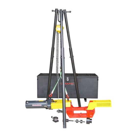
- Page 1 Instruction Manual Track Link Pin Pusher & Installer Model – TTP Series Maximum Operating Pressure – 700 bar ABSOLUTE EQUIPMENT PTY LTD – 2/186 Granite Street, GEEBUNG QLD 4034 – Australia sales@absoluteequipment.com.au – Phone: +61 7 3865 4006 – Fax:...
-
Page 2: Product Information
The user must ultimately make the decision regarding suitability of the product for any given task and assume the responsibility of safety for all in the work area. Contact a Durapac representative if you are unsure of your pin pusher’s suitability for a particular application. - Page 3 • Hydraulic equipment must only be serviced by a qualified hydraulic technician. For repair service, contact the Durapac authorised service centre in your area. To protect your warranty, use only high-quality hydraulic oil TTP Series – Pin Pusher – V1.4 www.durapac.com...
- Page 4 • Do NOT allow the hose to kink, twist, curl, crush, cut or bend so tightly that the fluid flow within the hose is blocked or reduced. Periodically inspect the hose for wear TTP Series – Pin Pusher – V1.4 www.durapac.com...
-
Page 5: Installation
Level the tripod by adjusting the leg height. 4.2.5 Adjust the leg chain by removing excess slack. 4.2.6 Position the chain pulley block directly under the U hook near the top of the tripod. TTP Series – Pin Pusher – V1.4 www.durapac.com Page 5 of 21... -
Page 6: System Specifications
Familiarise yourself with the specifications and illustrations in this owner’s manual. Know your pin pusher, its limitations and how it operates before attempting to use. Refer to the specification chart below or if in doubt, contact a Durapac representative. Working... -
Page 7: Operation
ɸ39.6 - ɸ42.8 ɸ42.8 - ɸ45.9 ɸ45.9 - ɸ52.3 ɸ52.3 - ɸ58.6 TTP-200 ɸ58.6 - ɸ60.2 ɸ60.2 - ɸ63.3 ɸ63.3 - ɸ66.6 ɸ66.6 - ɸ70.0 ɸ70.0 - ɸ73.9 TTP Series – Pin Pusher – V1.4 www.durapac.com Page 7 of 21... -
Page 8: Tool Selection
Figure 1 – TTP-50 Tool Selection Guide < End TTP-50 – Tool Selection Guide > Note - Your Durapac Distributor can supply, upon request, a Tooling Chart that will itemise different brands of machines, model numbers and track pin diameter. - Page 9 39.6 - 42.8 42.8 - 45.9 45.9 - 52.3 8c (saddle) 52.3 - 58.6 9c (saddle) 58.6 - 60.2 10c (saddle) < End TTP-100 – Tool Selection Guide > TTP Series – Pin Pusher – V1.4 www.durapac.com Page 9 of 21...
- Page 10 Diameter (mm) 22.0 - 41.9 Small Pin Group 4 Sets (1c,2c,3c,4c)(1b,2b,3b,4b)(1,2,3,4)(1a,2a,3a,4a) 41.9 - 57.1 Medium Pin Group 4 Sets (5c,6c,7c,8c)(5b,6b,7b,8b)(5,6,7,8)(5a,6a,7a,8a) 57.1 - 70.0 Large Pin Group 4 Sets (9c,10c,11c,12c)(9b,10b,11b,12b)(9,10,11,12)(9a,10a,11a,12a)(11d,12d) TTP Series – Pin Pusher – V1.4 www.durapac.com Page 10 of 21...
- Page 11 45.7 -50.8 50.8 - 53.8 53.8 - 57.1 57.1 - 60.3 60.3 - 63.3 63.3 - 66.6 66.6 - 70.0 < End TTP-150 – Tool Selection Guide > TTP Series – Pin Pusher – V1.4 www.durapac.com Page 11 of 21...
- Page 12 Diameter (mm) 36.4 - 45.9 Small Pin Group 3 Sets (1c,2c,3c)(1b,2b,3b)(1,2,3)(1a,2a,3a) 45.9 - 63.3 Medium Pin Group 4 Sets (4c,5c,6c,7c)(4b,5b,6b,7b)(4,5,6,7)(4a,5a,6a,7a) 63.3 - 73.9 Large Pin Group 3 Sets (8c,9c,10c)(8b,9b)(8,9,10)(8a,9a,9a)(1d) TTP Series – Pin Pusher – V1.4 www.durapac.com Page 12 of 21...
- Page 13 After use, the pin pusher should be stored with the piston fully retracted. Note - for ‘Large Pin Group’ refer “RAM WITHOUT SADDLE” from the above Tool Selection Guide. Figure 5 – TTP-50, TTP-100 & TTP-200 Pin Removal TTP Series – Pin Pusher – V1.4 www.durapac.com Page 13 of 21...
- Page 14 Instruction Manual Figure 6 – TTP-150 Pin Removal Example A Figure 7 – TTP-150 Pin Removal Example B Figure 8 – TTP-150 Pin Removal Example C TTP Series – Pin Pusher – V1.4 www.durapac.com Page 14 of 21...
- Page 15 After use, the pin pusher should be stored with the piston fully retracted. Figure 9 – TTP-50, TTP-100 & TTP-200 Pin Installation Figure 10 – TTP-150 Pin Installation Example A TTP Series – Pin Pusher – V1.4 www.durapac.com Page 15 of 21...
- Page 16 Instruction Manual Figure 11 – TTP-150 Pin Installation Example B Figure 12 – TTP-150 Pin Installation Example C TTP Series – Pin Pusher – V1.4 www.durapac.com Page 16 of 21...
- Page 17 Instruction Manual 5.4 Flat Jack Setup for Bushing Removal Not to Scale Figure 13 – Bushing Removal TTP Series – Pin Pusher – V1.4 www.durapac.com Page 17 of 21...
- Page 18 Instruction Manual Figure 14 – “Side Link” Bushing Removal TTP Series – Pin Pusher – V1.4 www.durapac.com Page 18 of 21...
-
Page 19: Maintenance
Durapac authorised service centre • Damage to hydraulic hoses may not be detected during visual inspections. For this reason, Durapac recommends that hydraulic hoses be replaced on a regular basis • Tighten connections as needed. Use non-hardening pipe thread compound when servicing connections Dirt, sand, etc. -
Page 20: Troubleshooting
Open release valve • or retracts slowly Cylinder damaged internally Send to a Durapac authorised service centre for repair • Reservoir too full Drain oil to correct level TTP Series – Pin Pusher – V1.4 www.durapac.com Page 20 of 21... -
Page 21: Parts Breakdown And List
Safety guards (set) Spacer Cylinder 20 Tonne Seal kit (not shown) Serial number and model need to be quoted when ordering parts. Repair kits are available on request. TTP Series – Pin Pusher – V1.4 www.durapac.com Page 21 of 21...
Need help?
Do you have a question about the TTP Series and is the answer not in the manual?
Questions and answers