
Related Manuals for APE 50


Summary of Contents for APE 50
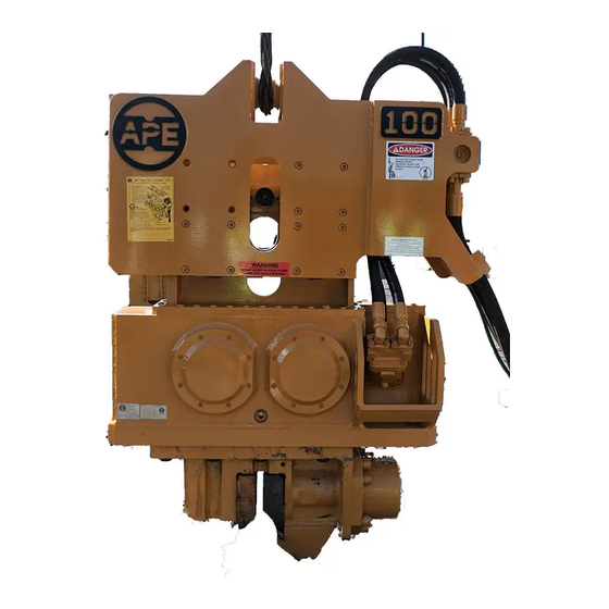
- Page 1 OPERATION AND MAINTENANCE MANUAL APE Model 50 with standard suppressor APE Model 50 with excavator suppressor (see page 2-2AB for parts details) SERIAL NUMBER: MODEL 50 VIBRO WITH MODEL 260 POWER UNIT...
-
Page 2: Revision Record
OPERATION / MAINTENANCE MANUAL MODEL 50 VIBRATORY HAMMER WITH MODEL 260 POWER UNIT 7032 SOUTH 196th - KENT, WA 98032 - (253) 872-0141 / FAX (253) 872-8710 7032 SOUTH 196th - KENT, WA 98032 - (253) 872-0141 / FAX (253) 872-8710... - Page 3 Preface General This manual covers the Model 50 Vibratory Hammer and the Model 260 Power Unit. The data provided in this manual gives the necessary information to operate and maintain APE equipment. The listed procedures are to be performed by qualified personnel who have an understanding of the equipment and who follow all safety precautions.
-
Page 4: Table Of Contents
OPERATION / MAINTENANCE MANUAL MODEL 50 VIBRATORY HAMMER WITH MODEL 260 POWER UNIT 7032 SOUTH 196th - KENT, WA 98032 - (253) 872-0141 / FAX (253) 872-8710 Table of Contents Page Revision Record ....................i Preface ......................... ii Table of Contents ....................iii Safety Precautions .................... -
Page 5: Table Of Contents
OPERATION / MAINTENANCE MANUAL MODEL 50 VIBRATORY HAMMER WITH MODEL 260 POWER UNIT 7032 SOUTH 196th - KENT, WA 98032 - (253) 872-0141 / FAX (253) 872-8710 Table of Contents (Continued...) V. MAINTENANCE (Continued...) V-7. Power Unit ...................... 5-3 A. Power Unit Filters, Fluid Types and Capacities ........5-3 B. -
Page 6: Safety Precautions
Do not use hoses as a tow line to tug the power unit! If a hose fails at the hydraulic couplers then it is a result of "hose tugging by the pile crew". 11. Avoid kinks in the hoses. Kinks will cut the hose safety factor by 50 percent. 12. Always wear eye and ear protection. -
Page 7: Illustration List
OPERATION / MAINTENANCE MANUAL MODEL 50 VIBRATORY HAMMER WITH MODEL 260 POWER UNIT 7032 SOUTH 196th - KENT, WA 98032 - (253) 872-0141 / FAX (253) 872-8710 Illustration List Figure Title Page 1-A. Machine Features ............1-1 1-B. General Description of 50 Vibro ........1-3 1-C. -
Page 8: Warranty
Refusal: Vibros: If the pile does not move one foot in 30 seconds of vibro operation (driving or pulling) at full speed. Resort to a larger vibro. APE/J&M equipment may exceed the refusal driving criteria for short periods of time as may be needed to penetrate hard soil layers or obstacles. -
Page 9: General Information
OPERATION / MAINTENANCE MANUAL MODEL 50 VIBRATORY HAMMER WITH MODEL 260 POWER UNIT 7032 SOUTH 196th - KENT, WA 98032 - (253) 872-0141 / FAX (253) 872-8710 I. GENERAL INFORMATION I-1. Machine Features APE MODEL 50 VIBRATORY DRIVER/EXTRACTOR FOR ALL TYPES OF PILE DRIVING AND EXTRACTING... -
Page 10: I-2. Machine Specifications
OPERATION / MAINTENANCE MANUAL MODEL 50 VIBRATORY HAMMER WITH MODEL 260 POWER UNIT 7032 SOUTH 196th - KENT, WA 98032 - (253) 872-0141 / FAX (253) 872-8710 I. GENERAL INFORMATION (Continued...) I-2. Machine Specifications Eccentric Moment 1300 I-2A. Model 50 Vibro - (Table 1-A.) -
Page 11: Model 50 Vibro
The Model 50 operates in a frequency range of 0 to 1800 cycles per minute depending on the hydraulic flow and on the hydraulic motors fitted to the gear train. The Model 50 is especially suited for driving or extracting piles that are near buildings or other structures. This is because the Model 50 vibrates at higher frequencies and thus is less damaging to surrounding soils. - Page 12 I-3A. The Suppressor Housing The suppressor housing of the Model 50 APE Vibrator is the top part of the vibro that attaches to the crane line. It is designed to absorb the vibration generated from the vibrator gearbox. Three different types of suppressors can be mounted to the APE Model 50 vibro.
- Page 13 The counterweight is filled, and therefore, enhanced with lead to increase eccentric moment. This design is unique to the industry and was developed by the engineers of APE to solve a number of problems associated with other types of vibrator machines. Both the eccentric and the drive gear have been helically cut to provide high speed operation with reduced noise and wear.
- Page 14 I. GENERAL INFORMATION (Continued...) I-3C. The Clamp Attachment The APE 50 comes with a standard sheet pile clamp attachment. The clamp contains two gripping jaws. One is "fixed" and one is "moveable." A large hydraulic cylinder operates the moveable jaw with up to 250 tons of clamping force depending on clamp pump relief pressure.
-
Page 15: Optional Attachments
I. GENERAL INFORMATION (Continued...) I-3D. Optional Attachments The following are some of the optional attachments for the APE Vibratory Hammers. (Contact APE or your local APE distributor for more information about these and other available equipment.) 7 ft. Caisson Beam (#901000) 8 ft. -
Page 16: I-4. General Description Of Model 260 Power Unit
I-4. General Description of Model 260 Power Unit The Model 50 vibrator runs off the APE 260 power unit. The APE 260 has a 260 horsepower CUMMINS 6CT8.3 engine. The engine is mounted to a tubular frame that also serves as a diesel fuel tank. A sheet metal and tube frame covers the engine and is equipped with locking doors for protection from the environment. - Page 17 OPERATION / MAINTENANCE MANUAL MODEL 50 VIBRATORY HAMMER WITH MODEL 260 POWER UNIT 7032 SOUTH 196th - KENT, WA 98032 - (253) 872-0141 / FAX (253) 872-8710 II. COMPONENT DEFINITION II-1. Component Identification - Model 50 Vibratory Hammer Figure 2-A. Component Identification.
-
Page 18: Ii-1. Component Identification
7032 SOUTH 196th - KENT, WA 98032 - (253) 872-0141 / FAX (253) 872-8710 II. COMPONENT DEFINITION (Continued...) II-1. Component Identification The following is a general listing of the APE 50 major components and part numbers. (Please see Figure 2-A. for component location.) Table 2-A. Component Identification... - Page 19 OPERATION / MAINTENANCE MANUAL MODEL 50 VIBRATORY HAMMER WITH MODEL 260 POWER UNIT 7032 SOUTH 196th - KENT, WA 98032 - (253) 872-0141 / FAX (253) 872-8710 Item Description part number Inner suppressor 312103 Outer suppressor 312102 Elastomer plate 311003...
- Page 20 OPERATION / MAINTENANCE MANUAL MODEL 50 VIBRATORY HAMMER WITH MODEL 260 POWER UNIT 7032 SOUTH 196th - KENT, WA 98032 - (253) 872-0141 / FAX (253) 872-8710 Page 2-2 B...
-
Page 21: Ii-2. Hose Identification
7032 SOUTH 196th - KENT, WA 98032 - (253) 872-0141 / FAX (253) 872-8710 II. COMPONENT DEFINITION (Continued...) II-2. Hose Identification The following is a general listing of the standard hoses that are shipped with the Model 50 Vibra- tory Hammer. (Please see Figure 2-B. for component location.) Table 2-B. Hose Identification... -
Page 22: Ii-3. Model 260 Power Unit Skid Identification
OPERATION / MAINTENANCE MANUAL MODEL 50 VIBRATORY HAMMER WITH MODEL 260 POWER UNIT 7032 SOUTH 196th - KENT, WA 98032 - (253) 872-0141 / FAX (253) 872-8710 II. COMPONENT DEFINITION (Continued...) II-3. Model 260 Power Unit Skid Identification -MODEL 260-... -
Page 23: Ii-4. Quick Disconnect Couplings
II. MAJOR COMPONENT DEFINITION (Continued...) II-4. Quick Disconnect Couplings The APE Quick Disconnect Couplings are high pressure hydraulic couplings designed for rugged applications. Service in many such applications has proven the design compatible to extreme pressures, structural and system induced shock loads. The construction of the coupling assembly promotes ease of use and maintenance. -
Page 24: Ii-5. Tool Set Identification
II-5. Tool Set Identification Mounted inside the Model 260 Power Unit is a set of tools frequently used for the maintenance of the APE Model 50 Vibratory Hammer. The following figure and table shows the location and the use for each tool. -
Page 25: Ii-6. Caisson Clamp Identification
7032 SOUTH 196th - KENT, WA 98032 - (253) 872-0141 / FAX (253) 872-8710 II. MAJOR COMPONENT DEFINITION (Continued...) II-6. Caisson Clamp Identification. The following is a general listing of the parts for the APE Caisson Clamp and Beams. (Please see Figure 2-F. for component location.) Table 2-F. Caisson Clamp Identification... - Page 26 OPERATION / MAINTENANCE MANUAL MODEL 50 VIBRATORY HAMMER WITH MODEL 260 POWER UNIT 7032 SOUTH 196th - KENT, WA 98032 - (253) 872-0141 / FAX (253) 872-8710 II. MAJOR COMPONENT DEFINITION (Continued...) II-6. Caisson Clamp Identification. (Continued...) BORE SECTION Figure 2-F. Caisson Clamp Identification.
-
Page 27: Iii. Loading And Unloading
III-1. Model 50 Vibratory Hammer The APE 50 vibrator is normally shipped laying flat on the trailer deck and the hose bundle is coiled on top. Lift the vibrator by rigging one line to the lifting pin and one line around the clamp attachment lifting the vibro and hose bundle as one load. -
Page 28: Iv. Preparation And Operation
The Vibro is fitted with a standard sheet clamp at the factory. However, several types of clamps are used on APE vibros to fit many different types of piles. A step by step procedure is provided as follows: 1.) Clean all drilled and tapped threads on the bottom surface of the gearbox. Use a 1 1/2"UNC tap to clean any rusted threads and blow out any remaining fragments with compressed air. -
Page 29: Iv-3. Plumbing The Vibro Hoses To The Power Unit
OPERATION / MAINTENANCE MANUAL MODEL 50 VIBRATORY HAMMER WITH MODEL 260 POWER UNIT 7032 SOUTH 196th - KENT, WA 98032 - (253) 872-0141 / FAX (253) 872-8710 IV. PREPARATION AND OPERATION (Continued...) IV-3. Plumbing the Vibro Hoses to the Power Unit There are five hoses leading from the vibro that must be connected to the power unit to begin operation (Please see section III-2. -
Page 30: Iv-4. Filling Vibrator Pressure Hoses
OPERATION / MAINTENANCE MANUAL MODEL 50 VIBRATORY HAMMER WITH MODEL 260 POWER UNIT 7032 SOUTH 196th - KENT, WA 98032 - (253) 872-0141 / FAX (253) 872-8710 IV. PREPARATION AND OPERATION (Continued...) IV-4. Filling Vibrator Pressure Hose The vibrator is shipped with the hoses filled with oil. However, if the unit has been sitting for a long period of time or if a damaged hose has been replaced with a new one, then the hoses must be filled. -
Page 31: Iv-6. Precautions And Rules For Operation
The following is a list of precautions, suggestions and rules that are intended to help promote the safe and productive use of the APE Model 50 Vibratory Hammer. 1.) Follow the Daily Maintenance Required Prior to Operation, [Section V-1.] [page 5-1]. -
Page 32: Iv-7. Relief Valve Settings Prior To Operation - Model 260
(800) 248-8498 IV-8. Shut-down Procedures The following procedures explain what to do with the power unit to correctly shut down the APE Model 50 Vibratory Hammer. 1.) Stop the vibrator. (Refer to the power unit operating manual .) 2.) Allow the diesel engine to run for five minutes at 1000 engine rpms. -
Page 33: Iv-9. Operation Of The Remote Control Pendant
Others prefer to give it to one of the ground crew so that he can position himself close to the work at hand. A 50 foot cord is provided as standard equipment. If this is not long enough, additional 50 foot sections can be added. Should the pendant become damaged, all functions can be manually operated. - Page 34 OPERATION / MAINTENANCE MANUAL MODEL 50 VIBRATORY HAMMER WITH MODEL 260 POWER UNIT 7032 SOUTH 196th - KENT, WA 98032 - (253) 872-0141 / FAX (253) 872-8710 BLANK Page...
-
Page 35: Maintenance
OPERATION / MAINTENANCE MANUAL MODEL 50 VIBRATORY HAMMER WITH MODEL 260 POWER UNIT 7032 SOUTH 196th - KENT, WA 98032 - (253) 872-0141 / FAX (253) 872-8710 V. MAINTENANCE V-1. Daily Maintenance Required Prior to Operation 1.) Visually inspect the entire vibro for loose nuts or bolts. Put a wrench on the clamp bolts and check them for tightness. -
Page 36: V-3. Maintenance And Adjustments
Clean the gearbox breathers each time the oil is changed. Replace the breathers if necessary. V-4. Maintenance and Adjustments (Eccentric Bearings) 1.) Model 50 - The Eccentric Bearings should be checked and/or replaced after every 5000 hours of operation. V-5. Maintenance and Adjustments in Severe Conditions When average temperature is above (80 deg. - Page 37 OPERATION / MAINTENANCE MANUAL MODEL 50 VIBRATORY HAMMER WITH MODEL 260 POWER UNIT 7032 SOUTH 196th - KENT, WA 98032 - (253) 872-0141 / FAX (253) 872-8710 V. MAINTENANCE (Continued...) V-7A. Power Unit - Filters, Fluid Types, and Capacities. (Table 5-A.)
-
Page 38: Hydraulic Fluid
V. MAINTENANCE (Continued...) V7-B. Power Unit - Hydraulic Fluid When adding or changing hydraulic fluid APE uses only Mobil 224 Hydraulic Vegetable oil which is non-toxic and will not harm oil or water and is biodegradable. Consult your local oil supplier for recommendations on mixing hydraulic oils. - Page 39 OPERATION / MAINTENANCE MANUAL MODEL 50 VIBRATORY HAMMER WITH MODEL 260 POWER UNIT 7032 SOUTH 196th - KENT, WA 98032 - (253) 872-0141 / FAX (253) 872-8710 V. MAINTENANCE (Continued...) V-7E. Power Unit - Changing Hydraulic Return Filter Element The hydraulic return filter is mounted on the hydraulic tank inside the power unit. It is mounted high on the tank so that when the filter element is removed the oil will not drain from the hydraulic tank.
-
Page 40: V-8. Hydraulic Motor - Installation And Start-Up
The table shows the highest recommended case pressure (F12 shaft seal type H) as a function of shaft speed.To obtain the longest seal life, the case pressure should be limited to 50% or less of the figures shown. NOTE: Contact VOAC Hydraulics for information on other shaft seals. - Page 41 OPERATION / MAINTENANCE MANUAL MODEL 50 VIBRATORY HAMMER WITH MODEL 260 POWER UNIT 7032 SOUTH 196th - KENT, WA 98032 - (253) 872-0141 / FAX (253) 872-8710 VI. VIBRO TROUBLE-SHOOTING The following table lists some possible problems, causes and solutions. If a serious problem should occur, contact the factory for additional service information.
- Page 42 OPERATION / MAINTENANCE MANUAL MODEL 50 VIBRATORY HAMMER WITH MODEL 260 POWER UNIT 7032 SOUTH 196th - KENT, WA 98032 - (253) 872-0141 / FAX (253) 872-8710 VI. VIBRO TROUBLE-SHOOTING (Continued...) Possible Cause Remedy 5. Opening and Closing Clamp Jaws Seems Spongy or Slow The plunger shaft may not be properly Remove the movable jaw from the clamp.
-
Page 43: Vii. Model 260 Power Unit
"A" is de-energized. Because of the high oil flow in the drive circuit, APE, Inc. has developed a circuit that eliminates high shock loads. Items #30, 27, & 24 are small internal components located in the drive manifold that provide a soft shift feature for the drive directional control valve. - Page 44 OPERATION / MAINTENANCE MANUAL MODEL 50 VIBRATORY HAMMER WITH MODEL 260 POWER UNIT 7032 SOUTH 196th - KENT, WA 98032 - (253) 872-0141 / FAX (253) 872-8710 VII. MODEL 260 POWER UNIT (Continued...) VII-1C. Return Filter. Returning fluid is filtered by the return filter item #8.
-
Page 45: Hydraulic Schematic
OPERATION / MAINTENANCE MANUAL MODEL 50 VIBRATORY HAMMER WITH MODEL 260 POWER UNIT 7032 SOUTH 196th - KENT, WA 98032 - (253) 872-0141 / FAX (253) 872-8710 VII. MODEL 260 POWER UNIT (Continued...) VII-1H. Hydraulic Schematic. Figure 7-A. Power Unit Hydraulic Scematic. -
Page 46: Vii-2. Electrical Circuitry
7032 SOUTH 196th - KENT, WA 98032 - (253) 872-0141 / FAX (253) 872-8710 VII. MODEL 260 POWER UNIT (Continued...) VII-2. Electrical Circuitry The following are descriptions of components that make up the Electric Circuitry of the APE Model 260 Power Unit. VII-2A. Diesel Engine The HYDRAULIC POWER UNIT is powered by a 4 stroke compression ignition diesel engine. - Page 47 OPERATION / MAINTENANCE MANUAL MODEL 50 VIBRATORY HAMMER WITH MODEL 260 POWER UNIT 7032 SOUTH 196th - KENT, WA 98032 - (253) 872-0141 / FAX (253) 872-8710 VII. MODEL 260 POWER UNIT (Continued...) VII-2B. Controls: (Understanding How They Work) (Continued...) 3.
- Page 48 This switch is used to throttle the engine up or down. This switch turns a small motor hooked to the engine throttle. APE power units with CAT engines use a system supplied by CAT. The CAT engine throttle requires two small relays mounted inside the control panel. The APE units with Cummins engines do not have relays and are wired directly to a Murphy worm drive throttle box mounted on the engine.
-
Page 49: Preparing The Electrical System For Start-Up
OPERATION / MAINTENANCE MANUAL MODEL 50 VIBRATORY HAMMER WITH MODEL 260 POWER UNIT 7032 SOUTH 196th - KENT, WA 98032 - (253) 872-0141 / FAX (253) 872-8710 VII. MODEL 260 POWER UNIT (Continued...) VII-2B. Controls: (Understanding How They Work) (Continued...) 12. -
Page 50: Engine Safety Shut-Down (Three Causes Of Engine Shut-Down)
OPERATION / MAINTENANCE MANUAL MODEL 50 VIBRATORY HAMMER WITH MODEL 260 POWER UNIT 7032 SOUTH 196th - KENT, WA 98032 - (253) 872-0141 / FAX (253) 872-8710 VII. MODEL 260 POWER UNIT (Continued...) VII-2F. Engine Safety Shut-Down (Three Causes Of Engine Shut-Down) 1. -
Page 51: Vii-3. Remote Control Pendant
A "REMOTE HAND HELD CONTROL PENDANT" is provided to allow operation of the power unit at a distance of up to 50 feet (15 meters) and can be extended using 50 foot extension cables. The "REMOTE HAND HELD CONTROL PENDANT" is connected to the control panel via a multiconnector plug. -
Page 52: Remote Pendant Wiring Diagram
OPERATION / MAINTENANCE MANUAL MODEL 50 VIBRATORY HAMMER WITH MODEL 260 POWER UNIT 7032 SOUTH 196th - KENT, WA 98032 - (253) 872-0141 / FAX (253) 872-8710 VII. MODEL 260 POWER UNIT (Continued...) VII-3A. Remote Pendant Wiring Diagram The following is the pin wiring configuration and the wire colors of the amphenol connectors for the remote control pendant cable. -
Page 53: Water Temperature Switch
OPERATION / MAINTENANCE MANUAL MODEL 50 VIBRATORY HAMMER WITH MODEL 260 POWER UNIT 7032 SOUTH 196th - KENT, WA 98032 - (253) 872-0141 / FAX (253) 872-8710 VII. MODEL 260 POWER UNIT (Continued...) VII-4. Troubleshooting: Power Unit Electrical Use the following sections to help determine and solve problems that may arise within the power unit electrical system. -
Page 54: Oil Pressure Sending Unit (Cummins Engines)
OPERATION / MAINTENANCE MANUAL MODEL 50 VIBRATORY HAMMER WITH MODEL 260 POWER UNIT 7032 SOUTH 196th - KENT, WA 98032 - (253) 872-0141 / FAX (253) 872-8710 VII. MODEL 260 POWER UNIT (Continued...) VII-4. Troubleshooting: Power Unit Electrical (Continued...) VII-4D. Troubleshooting: Oil Pressure Sending Unit (CAT Engines Only) An electric "OIL PRESSURE GAUGE"... -
Page 55: Vii-5. Electrical Schematic
OPERATION / MAINTENANCE MANUAL MODEL 50 VIBRATORY HAMMER WITH MODEL 260 POWER UNIT 7032 SOUTH 196th - KENT, WA 98032 - (253) 872-0141 / FAX (253) 872-8710 VII. MODEL 260 POWER UNIT (Continued...) VII-5. Electrical Schematic. Page 7-13... -
Page 56: Appendix A - Cummins 6Ct8.3 Engine
CUMMINS 6CT8.3 ENGINE A-1. ENGINE OPERATION INSTRUCTIONS The following sections are basic instructions for maintenance and operation of the APE Model 260 Power Unit Engines. All maintenance should be performed by qualified personnel who are familiar with the equipment. (Consult the factory for additional information.) A-1A. - Page 57 OPERATION / MAINTENANCE MANUAL MODEL 50 VIBRATORY HAMMER WITH MODEL 260 POWER UNIT 7032 SOUTH 196th - KENT, WA 98032 - (253) 872-0141 / FAX (253) 872-8710 - APPENDIX A - CUMMINS 6CT8.3 ENGINE A-1B. STARTING THE ENGINE CAUTION: Do not engage the starter when the flywheel is moving.
- Page 58 OPERATION / MAINTENANCE MANUAL MODEL 50 VIBRATORY HAMMER WITH MODEL 260 POWER UNIT 7032 SOUTH 196th - KENT, WA 98032 - (253) 872-0141 / FAX (253) 872-8710 - APPENDIX A - CUMMINS 6CT8.3 ENGINE A-1. OPERATION INSTRUCTIONS (Continued...) A-1C. ENGINE OPERATION After the engine starts, and at frequent intervals while the engine is operating, the gauges should be observed.
- Page 59 OPERATION / MAINTENANCE MANUAL MODEL 50 VIBRATORY HAMMER WITH MODEL 260 POWER UNIT 7032 SOUTH 196th - KENT, WA 98032 - (253) 872-0141 / FAX (253) 872-8710 - APPENDIX A - CUMMINS 6CT8.3 ENGINE A-1C. ENGINE OPERATION (Continued...) Water Temperature Gauge...
- Page 60 OPERATION / MAINTENANCE MANUAL MODEL 50 VIBRATORY HAMMER WITH MODEL 260 POWER UNIT 7032 SOUTH 196th - KENT, WA 98032 - (253) 872-0141 / FAX (253) 872-8710 - APPENDIX A - CUMMINS 6CT8.3 ENGINE A-1C. ENGINE OPERATION (Continued...) Altitude Operation The fuel system settings and altitude limits are stamped on the engine information plate.
-
Page 61: Starting The Engine
OPERATION / MAINTENANCE MANUAL MODEL 50 VIBRATORY HAMMER WITH MODEL 260 POWER UNIT 7032 SOUTH 196th - KENT, WA 98032 - (253) 872-0141 / FAX (253) 872-8710 - APPENDIX A - CUMMINS 6CT8.3 ENGINE A-1C. ENGINE OPERATION (Continued...) Starting The Engine 1. -
Page 62: Determining Cause Of Shutdown
OPERATION / MAINTENANCE MANUAL MODEL 50 VIBRATORY HAMMER WITH MODEL 260 POWER UNIT 7032 SOUTH 196th - KENT, WA 98032 - (253) 872-0141 / FAX (253) 872-8710 - APPENDIX A - CUMMINS 6CT8.3 ENGINE A-1D. Determining Cause Of Shutdown CAUTION: If the engine has been shutdown by a safety device, don't start the engine and... - Page 63 High Water Temperature Checks-Engine Stopped and Cold 1. Check coolant level. Determine if the coolant has proper antifreeze protection. A 50-50 solution of permanent-type antifreeze and approved water will give protection below -200F (-290C). 2. Check to be sure the raw water valve has been opened.
-
Page 64: A-2. Maintenance Recommendations
OPERATION / MAINTENANCE MANUAL MODEL 50 VIBRATORY HAMMER WITH MODEL 260 POWER UNIT 7032 SOUTH 196th - KENT, WA 98032 - (253) 872-0141 / FAX (253) 872-8710 - APPENDIX A - CUMMINS 6CT8.3 ENGINE A-2. MAINTENANCE RECOMMENDATIONS CAUTION: Never add coolant to an overheated engine; allow the engine to cool first. -
Page 65: Lubrication Specifications
OPERATION / MAINTENANCE MANUAL MODEL 50 VIBRATORY HAMMER WITH MODEL 260 POWER UNIT 7032 SOUTH 196th - KENT, WA 98032 - (253) 872-0141 / FAX (253) 872-8710 - APPENDIX A - CUMMINS 6CT8.3 ENGINE A-2. MAINTENANCE RECOMMENDATIONS (Continued...) Fuel CAUTION: Fill fuel tank at the end of each day of operation to drive out moisture-laden air and to prevent condensation. -
Page 66: Fuel Specifications
OPERATION / MAINTENANCE MANUAL MODEL 50 VIBRATORY HAMMER WITH MODEL 260 POWER UNIT 7032 SOUTH 196th - KENT, WA 98032 - (253) 872-0141 / FAX (253) 872-8710 - APPENDIX A - CUMMINS 6CT8.3 ENGINE A-2. MAINTENANCE RECOMMENDATIONS (Continued...) A-2B. FUEL SPECIFICATIONS No. -
Page 67: Lubrication And Maintenance
OPERATION / MAINTENANCE MANUAL MODEL 50 VIBRATORY HAMMER WITH MODEL 260 POWER UNIT 7032 SOUTH 196th - KENT, WA 98032 - (253) 872-0141 / FAX (253) 872-8710 - APPENDIX A - CUMMINS 6CT8.3 ENGINE A-2. MAINTENANCE RECOMMENDATIONS (Continued...) A-2D. LUBRICATION AND MAINTENANCE The LUBRICATION AND MAINTENANCE CHART lists all serviceable items commonly ordered on this engine. -
Page 68: Electrical System
OPERATION / MAINTENANCE MANUAL MODEL 50 VIBRATORY HAMMER WITH MODEL 260 POWER UNIT 7032 SOUTH 196th - KENT, WA 98032 - (253) 872-0141 / FAX (253) 872-8710 - APPENDIX A - CUMMINS 6CT8.3 ENGINE A-2E. ELECTRICAL SYSTEM The following topics describe care and maintenance of the electrical system components. -
Page 69: A-3. Engine Troubleshooting
OPERATION / MAINTENANCE MANUAL MODEL 50 VIBRATORY HAMMER WITH MODEL 260 POWER UNIT 7032 SOUTH 196th - KENT, WA 98032 - (253) 872-0141 / FAX (253) 872-8710 - APPENDIX A - CUMMINS 6CT8.3 ENGINE A-2E. ELECTRICAL SYSTEM (Continued...) Charging the Battery WARNING: Never smoke in the area where batteries are being charged. - Page 70 OPERATION / MAINTENANCE MANUAL MODEL 50 VIBRATORY HAMMER WITH MODEL 260 POWER UNIT 7032 SOUTH 196th - KENT, WA 98032 - (253) 872-0141 / FAX (253) 872-8710 - APPENDIX A - CUMMINS 6CT8.3 ENGINE A-3. Engine Troubleshooting (Continued...) Possible Causes Remedy 1.
- Page 71 OPERATION / MAINTENANCE MANUAL MODEL 50 VIBRATORY HAMMER WITH MODEL 260 POWER UNIT 7032 SOUTH 196th - KENT, WA 98032 - (253) 872-0141 / FAX (253) 872-8710 - APPENDIX A - CUMMINS 6CT8.3 ENGINE A-3. Engine Troubleshooting (Continued...) Possible Causes Remedy 3.
- Page 72 OPERATION / MAINTENANCE MANUAL MODEL 50 VIBRATORY HAMMER WITH MODEL 260 POWER UNIT 7032 SOUTH 196th - KENT, WA 98032 - (253) 872-0141 / FAX (253) 872-8710 - APPENDIX A - CUMMINS 6CT8.3 ENGINE A-3. Engine Troubleshooting (Continued...) Possible Causes Remedy 6.
- Page 73 OPERATION / MAINTENANCE MANUAL MODEL 50 VIBRATORY HAMMER WITH MODEL 260 POWER UNIT 7032 SOUTH 196th - KENT, WA 98032 - (253) 872-0141 / FAX (253) 872-8710 - APPENDIX A - CUMMINS 6CT8.3 ENGINE A-3. Engine Troubleshooting (Continued...) Possible Causes Remedy 10.
- Page 74 OPERATION / MAINTENANCE MANUAL MODEL 50 VIBRATORY HAMMER WITH MODEL 260 POWER UNIT 7032 SOUTH 196th - KENT, WA 98032 - (253) 872-0141 / FAX (253) 872-8710 - APPENDIX A - CUMMINS 6CT8.3 ENGINE A-3. Engine Troubleshooting (Continued...) Possible Causes Remedy 13.
- Page 75 OPERATION / MAINTENANCE MANUAL MODEL 50 VIBRATORY HAMMER WITH MODEL 260 POWER UNIT 7032 SOUTH 196th - KENT, WA 98032 - (253) 872-0141 / FAX (253) 872-8710 - APPENDIX A - CUMMINS 6CT8.3 ENGINE A-3. Engine Troubleshooting (Continued...) Possible Causes Remedy 17.
- Page 76 OPERATION / MAINTENANCE MANUAL MODEL 50 VIBRATORY HAMMER WITH MODEL 260 POWER UNIT 7032 SOUTH 196th - KENT, WA 98032 - (253) 872-0141 / FAX (253) 872-8710 - APPENDIX A - CUMMINS 6CT8.3 ENGINE A-3. Engine Troubleshooting (Continued...) Possible Causes Remedy 22.
- Page 77 OPERATION / MAINTENANCE MANUAL MODEL 50 VIBRATORY HAMMER WITH MODEL 260 POWER UNIT 7032 SOUTH 196th - KENT, WA 98032 - (253) 872-0141 / FAX (253) 872-8710 - APPENDIX A - CUMMINS 6CT8.3 ENGINE A-3. Engine Troubleshooting (Continued...) Possible Causes Remedy 22.
- Page 78 OPERATION / MAINTENANCE MANUAL MODEL 50 VIBRATORY HAMMER WITH MODEL 260 POWER UNIT 7032 SOUTH 196th - KENT, WA 98032 - (253) 872-0141 / FAX (253) 872-8710 - APPENDIX A - CUMMINS 6CT8.3 ENGINE A-3. Engine Troubleshooting (Continued...) Possible Causes Remedy 26.
Need help?
Do you have a question about the 50 and is the answer not in the manual?
Questions and answers